Coupled Aerodynamic and Hydrodynamic Analysis of Floating Offshore Wind Turbine Using CFD Method
2016-05-12WuJunMengLongZhaoYongshengHeYanping1StateKeyLaboratoryofOceanEngineeringShanghaiJiaoTongUniversityShanghai200240ChinaCollaborativeInnovationCenterforAdvancedShipandDeepSeaExplorationCISSEShanghai200240ChinaSchoolofNava
Wu Jun,Meng Long*,Zhao Yongsheng,He Yanping1.State Key Laboratory of Ocean Engineering,Shanghai Jiao Tong University,Shanghai 200240,P.R.China;2.Collaborative Innovation Center for Advanced Ship and Deep-Sea Exploration (CISSE),Shanghai 200240,P.R.China;3.School of Naval Architecture,Ocean&Civil Engineering,Shanghai Jiao Tong University,Shanghai 200240,P.R.China (Received 18 August 2015; revised 20 November 2015; accepted 5 January 2016)
* Corresponding author,E-mail address: menglong201504@ sjtu.edu.cn.
How to cite this article: Wu Jun,Meng Long,Zhao Yongsheng,et al.Coupled aerodynamic and hydrodynamic analysis of float
ing offshore wind turbine using CFD method[J].Trans.Nanjing Univ.Aero.Astro.,2016,33(1) : 80-87.
http: / /dx.doi.org/10.16356/j.1005-1120.2016.01.080
Coupled Aerodynamic and Hydrodynamic Analysis of Floating Offshore Wind Turbine Using CFD Method
Wu Jun1,2,3,Meng Long1,2,3*,Zhao Yongsheng1,2,3,He Yanping1,2,31.State Key Laboratory of Ocean Engineering,Shanghai Jiao Tong University,Shanghai 200240,P.R.China;
2.Collaborative Innovation Center for Advanced Ship and Deep-Sea Exploration (CISSE),Shanghai 200240,P.R.China;
3.School of Naval Architecture,Ocean&Civil Engineering,Shanghai Jiao Tong University,Shanghai 200240,P.R.China (Received 18 August 2015; revised 20 November 2015; accepted 5 January 2016)
* Corresponding author,E-mail address: menglong201504@ sjtu.edu.cn.
How to cite this article: Wu Jun,Meng Long,Zhao Yongsheng,et al.Coupled aerodynamic and hydrodynamic analysis of float
ing offshore wind turbine using CFD method[J].Trans.Nanjing Univ.Aero.Astro.,2016,33(1) : 80-87.
http: / /dx.doi.org/10.16356/j.1005-1120.2016.01.080
Abstract:To simulate floating offshore wind turbine (FOWT) in coupled wind-wave domain via CFD method,the NREL 5 MW wind turbine supported by the OC3-Hywind Spar platform is modeled in the STAR-CCM + software.Based on the Reynolds-averaged Navier-Stokes (RANS) equations and re-normalisation group (RNG) k-ε turbulence model,the rotor aerodynamic simulation for wind turbine is conducted.Numerical results agree well with the NREL data.Taking advantage with the volume of fluid (VOF) method and dynamic fluid body interaction (DFBI) technology,the dynamic responses of the floating system with mooring lines are simulated under the coupled wind-wave sea condition.The free-decay tests for rigid-body degrees of freedom (DOFs) in still water and hydrodynamic tests in a regular wave are performed to validate the numerical model by comparing its result with the results simulated by FAST.Finally,the simulations of the overall FOWT system in the coupled wind-wave flow field are carried out.The relationship between the power output and dynamic motion responses of the platform is investigated.The numerical results show that the dynamic response of wind turbine performance and platform motions all vary in the same frequency as the inlet wave.During platform motion,the power output of wind turbine is more sensitive than the thrust force.This study may provide some reference for further research in the coupled aerohydro simulation of FOWT.
Key words:floating offshore wind turbine (FOWT) ; computational fluid dynamics (CFD) ; aerodynamic performance; dynamic fluid body interaction
CLC number: TM614; TK89Document code: AArticle ID: 1005-1120(2016)01-0080-08
0 Introduction
Those years,exploitation of offshore wind energy has contributed greatly to rapid progress in floating offshore wind turbine (FOWT) technology.The world's first floating full-scale wind turbine″Hywind″,was successfully operated in the North Sea off Norway in 2009.Since then,various FOWT prototypes,such as SWAY (spar type),Blue H (TLP type) and WindFloat (semi-submersible type) have been installed.The highly complex marine environments,e.g.turbulent wind,irregular wave,ocean current,bring enormous challenges to the research of FOWT technology.
The FOWT aerodynamic aspects are more complicated than onshore wind turbines,because the wind turbine on floating platform experiences larger motions induced by wave and current combined with aerodynamic loads.And the fluctuations of aerodynamic loads resulting from wind turbine also affect the platform motions.Currently,researchers have been paying increasing attentions to the coupled aerodynamic and hydrodynamic analysis of FOWT system.Jonkman[1-3]proposed a fully coupled time domain aero-hydro-servo-elastic simulation tool FAST with AeroDyn and HydroDyn modules,which accounts for the wind inflow,aerodynamics,elasticity and controls of the wind turbine,along with the incident waves,current,hydrodynamics,and platform and mooring dynamics of the floater.He presented the develop-ment and verification of a comprehensive simulator for modelling the coupled dynamic response of offshore floating wind turbines through model-to-model comparisons.Ren et al.[4]developed a coupled windwave model of typical TLP FOWT based on computational fluid dynamics (CFD) method,where the aerodynamic loads on NREL 5 MW wind turbine have been determined by solving Navier-Stokes(N-S) equations,and the hydrodynamic loads on floating platform have been simulated by viscous numerical flume based on volume of fluid (VOF) method.Quallen[5]applied crowfoot mooring line model in the OC3-Hywind FOWT system.Six degrees of freedom (DOFs) free-decay and regular wave tests were conducted using CFD Ship-Iowa solver to analyze the hydrodynamic performance,and the simulations agreed well with FAST result developed by NREL.Matha[6]discussed the unique aerodynamics,hydrodynamics,and mooring-line dynamic effects occurring on FOWTs due to large rotor and platform motions.The aerodynamic results of wind turbine using CFD method showed the complex flow conditions at the rotor occurring during a representative platform pitch motion.The significance of second-order linear hydrodynamics and vortex-induced vibrations for FOWT simulations are analyzed.Karimirad[7]addressed the wave and wind induced responses of a catenary moored spar floating wind turbine in operational conditions.The role of hydrodynamic and aerodynamic damping in different frequency ranges for dynamic motion responses and electrical power production has been investigated.Kvittem[8]developed a coupled simulation code by linking SIMO-RIFLEX-AeroDyn-TurbSim computational tools to examine the dynamic response of a semi-submersible wind turbine.Results showed that platform motions are sensitive to the choice of added mass coefficients and the pitch motions would influence the power production and blade bending moment.
In this paper,CFD method is adopted to analyze the aerodynamics and hydrodynamics of FOWT,and the OC3-Hywind[9]spar of floating wind turbine system is chosen for the objective.The aerodynamic performance of the NREL 5 MW wind turbine[10]is simulated based on Reynolds-averaged Navier-Stokes(RANS) equations and renormalisation group (RNG) k-ε turbulence model.The validation of rotor aerodynamic study is achieved by comparing with NREL design data.Besides,the dynamic motions of floating platform with catenary mooring lines are simulated by dynamic fluid body interaction (DFBI) model.The free decay tests and regular wave tests for platform are conducted and test results agree well with those simulated by FAST.Finally,the simulations of overall floating wind turbine system in the coupled windwave flow field are successfully conducted.The relationship between the power output and dynamic motion response of the platform is investigated and the results provide some reference for further research in coupled aero-hydro simulation of FOWT.
1 Numerical Method
1.1Governing equations
The conservation equations for mass continuity and momentum based on Reynolds time averaged method are as follows
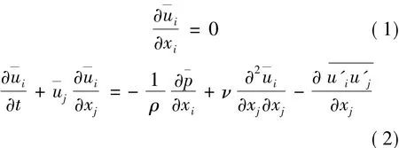
where i,j= 1,2,3 ; air density ρ= 1.255 kg/m3; kinematic viscosity ν= 1.789 4×10⁻⁵kg/(m·s) ; 珔uirespresents the time-averaged velocity component in the i direction,u'jthe fluctuating velocity component in the j direction,and xithe component of position vector in the i direction.
The RNG k-ε turbulence model is derived from the instantaneous N-S equations,using a mathematical technique called the RNG methods.The analytical derivation results in a model with constants different from those in the standard k-ε model,and additional terms and functions in the transport equations for k and ε.The transport equations for the RNG k-ε model are as follows


where Gkrepresents the generation of turbulence kinetic energy due to the mean velocity gradients,Gbthe generation of turbulence kinetic energy due to buoyancy,and YMthe contribution of the fluctuating dilatation in compressible turbulence to the overall dissipation rate.αkand αεare the inverse effective Prandtl numbers for k and ε,respectively.Skand Sεrepresent the user-defined source terms.
1.2Motion equations of FOWT
The wave propagation is supposed to be in the same direction as the wind,and a regular wave is used in the simulation.Three DOFs of the floating platform are released,i.e.,surge,heave and pitch.Taking the effects of dynamic responses of wind turbine,tower force and mooring system into consideration,the equation of FOWT motions is expressed as

where x =[ x1,x2,x3]is the vector containing the surge ? translation,heave translation and pitch rotation of the platform.M is the structural mass matrix.Cwaveand Cwindrepresent the hydrodynamic damping and aerodynamic damping,respectively; Kmooringrepresents the stiffness matrix caused by mooring lines.Fthrust,Ftowerand Fwaverepresent the thrust force,wind force acting on tower and wave force on the platform,respectively.
1.3Catenary mooring line equations

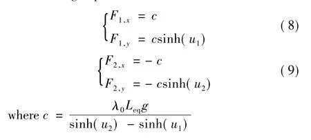
An elastic,quasi-stationary catenary model was used in simulation of mooring lines,which do not take the touchdown effects and nonlinear drag into account[11].The mooring line is subject to its own weight and in a local Cartesian coordinate system its shape (see Fig.1) is given by the following equations. where λ0and Leqare the mass per unit length in water and the relaxation length of mooring line,respectively.D is the stiffness of the catenary.α and β are the integration constants depending on the position of two ends and the total mass of the catenary.The curve parameter u is related to the inclination angle of the catenary curve by the following equation.

The parameter value u1and u2represent the positions of the catenary's end points p1and p2in parameter space.
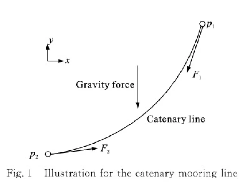
Fig.1 Illustration for the catenary mooring line
The forces acting on the two ends are given by the following expressions.
2 Computational Modeling of FOWT
Here,the well-known NREL 5-MW baseline wind turbine model is investigated.The specification of the wind turbine is presented in Table 1.The OC3-Hywind spar platform with catenary mooring lines is chosen to support the wind turbine,and the detailed properties are listed in Tables 2,3.
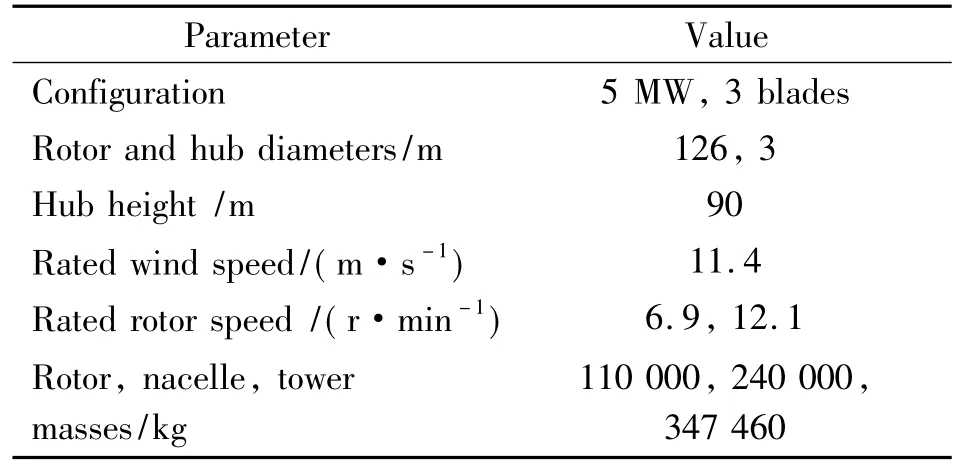
Table 1 NREL 5 MW wind turbine properties[10]
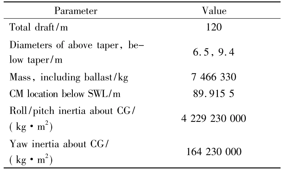
Table 2 OC3-Hywind spar platform properties[12]
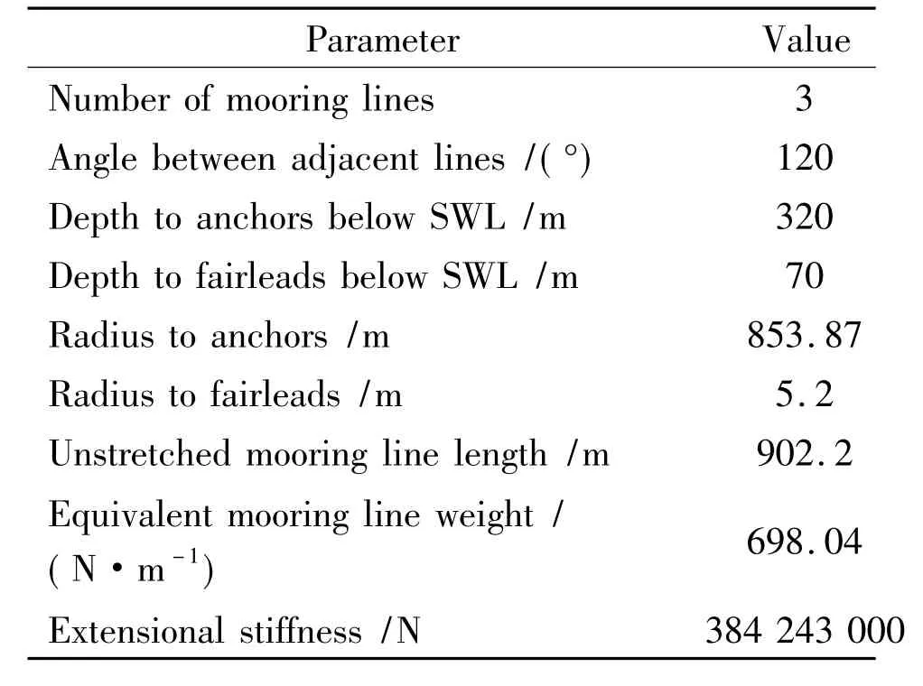
Table 3 Mooring system properties[12]
The computational domain is divided into the rotating and outer domains,as shown in Fig.2.The dimension of the outer domain extends 700 m in length,300 m in width and 600 m in height.In order to capture the development of wake behind the turbine,the wake area is attributed with fine meshes.The water surface near the platform is also refined for accurate calculation of the hydrodynamic force.Near the rotor surface,the boundary layers have 12 layers of refined grid with the first layer thickness of 2× 10⁻³m and a progression factor of 1.2.The total element number of the computational domain is approximately 6.2 million.Fig.3.shows the surface grid and mesh sections.
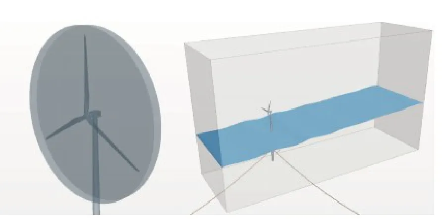
Fig.2 Rotating and outer domian

Fig.3 Surface grid and mesh section
The Eulerian multiphase model and VOF method are adopted to simulate the wind-wave flow field.Velocity inlet condition is prescribed in the upstream,bottom and top of the domain,and pressure outlet condition is set in the downstream boundary.At far field of the outer domain,the symmetric boundary is specified.Dynamic fluid body interaction (DFBI) translation and rotation are prescribed in the outer region,and the DFBI superimposed rotation is attributed to the rotating region.Furthermore,interfaces are established to translate the flow filed information among the two regions.
3 Results and Discussion
The simulation begins with rotor-only simulation for wind turbine to test the availability of aerodynamic model.The next procedure follows with hydrodynamic tests of the platform,including a free-decay test and a regular wave test.The last part involves the coupled wind-wave simulation of FOWT system.The simulation specifications are presented in Table 4.

Table 4 Simulation specifications for FOWT
3.1Aerodynamic tests
Aerodynamic simulations of wind turbine with various wind velocities and rotating speeds are conducted by the multi reference frames (MRFs) method for steady simulation and the rotation method for unsteady simulation,respectively.The obtained thrust force and power output are compared with the corresponding NREL data calculated by FAST,as plotted in Fig.4.The obtained rotor power agrees well with the corresponding NREL data,while the thrust force tends to be smaller than that from NREL design data.At the rated wind speed of 11.4 m/s,the thrust force predicted by the CFD method is 9.0%,being less than that of the FAST method.The difference between the CFD method and FAST can be explained by the dynamic stall occurred at mid-sections of the blade when the wind speed is relatively higher.As divergence is within an acceptable range,the above results verify the availability of aerodynamic model.
3.2Free decay test
Six DOFs free decay tests are conducted to test the hydrodynamic damping characteristics of the OC3-hywind spar platform.Wave mode is set as still water and air density is zero.Only platform is considered in the simulation.For simplification,half of the platform is modeled in the STAR-CCM + software.The platform is perturbed a prescribed displacement and released to move freely from the initial position.This test considers only three rigidbody DOFs,that is,the surge,pitch and heave motions.The results are presented in Fig.5 along with the results calculated by FAST.The CFD results are in good agreement with those of FAST both in pitch and heave motions,while the result in the surge motion (0.007 65 Hz) predicts a lower frequency than that of FAST (0.008 02 Hz).The HydroDyn module in FAST utilizes the linear potential flow theory augmented with the nonlinear viscous-dragtermfromMorison's equation[13].STAR-CCM + numerically solves the N-S equations,calculating the hydrodynamic forces through pressure integration along wet surface.The differences between these two solution methods help to explain the frequency differences displayed in surge decay test and a small damping discrepancy seen in pitch motion.
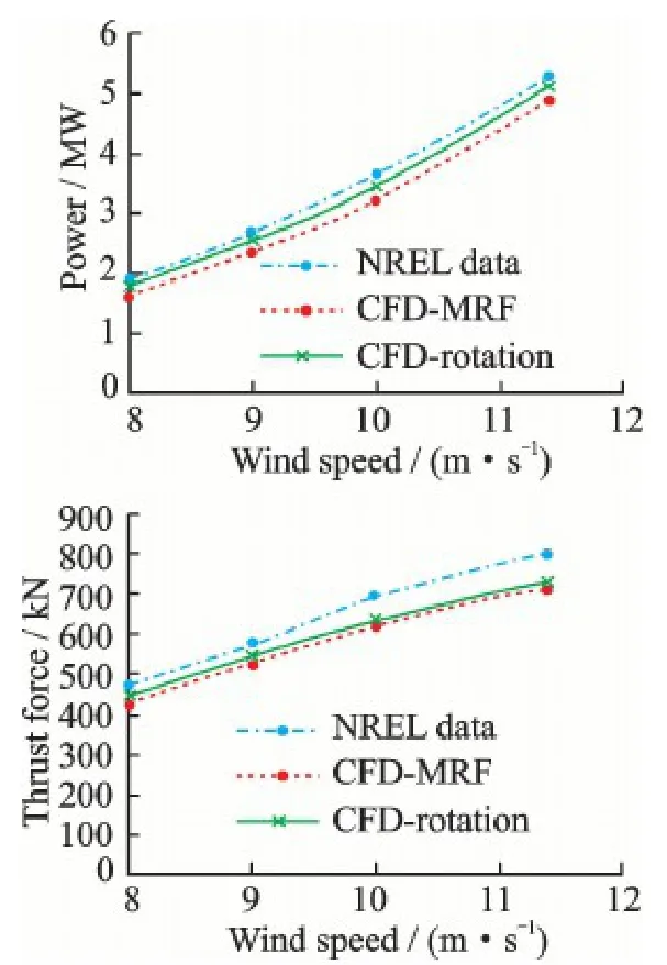
Fig.4 Comparisons of thrust force and power output
3.3Regular wave test
The platform is initialized at static position and a regular wave is introduced with the parameters shown in Table 5.The transient start-up period has been removed from the results,and the responses of the surge,heave and pitch motions are plotted in Fig.6 along with the FAST results.Thetime series of platform motion responds as the similar frequency with incident wave (0.1 Hz).The dynamic ranges of the platform motions are narrower than that predicted by NREL-FAST.This difference is likely due to FAST's usage of a constant drag coefficient in Morison' s equation for calculating wave force.And the potential flow theory produced by FAST has no means in determining non-linear viscous effects and vortex shedding.
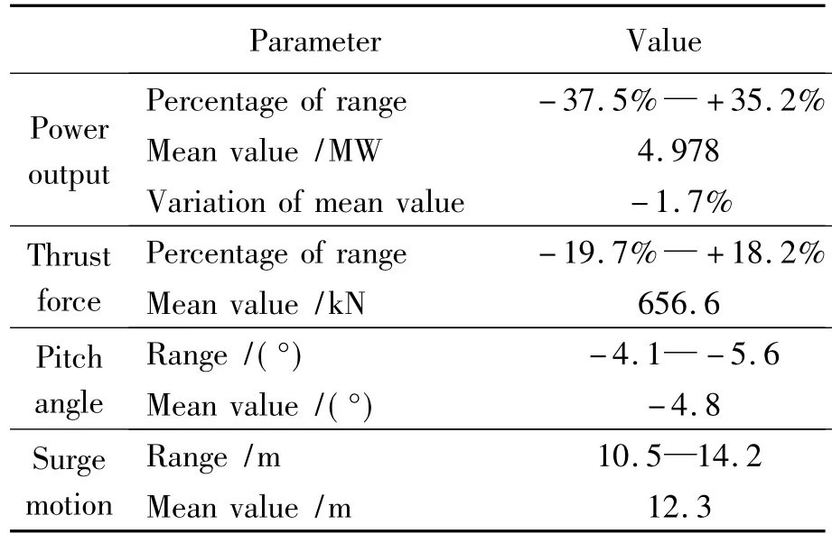
Table 5 Variation of aerodynamic loads and platform motions

Fig.5 Surge,pitch and heave results of free decay test

Fig.6 Results of regular wave test
3.4Coupled wind-wave simulation
Considering the effect of coupled wind-wave field,the simulation introduces the regular wave with 2 m amplitude and 10 s period,as well as the steady wind with 11.4 m/s.After 20 s start-up time,the aerodynamic output for wind turbine is stabilized and the platform is released to move.The computational flow chart for FOWT is presented in Fig.7.The iso-surface of vorticity behind the wind turbine and the development of wind-wave flow field are illustrated in Figs.8,9,respectively.
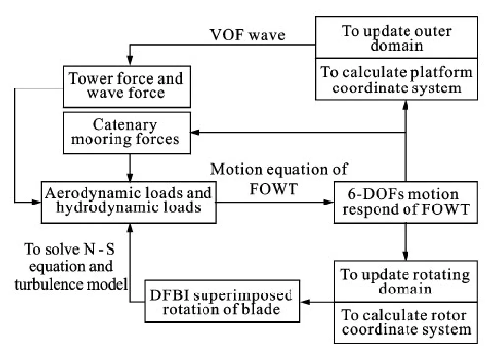
Fig.7 Computational flow chart for coupled aerodynamic and hydrodynamic analysis of FOWT
The power output and thrust force time-histories for the coupled simulation are present in Fig.10 along with the dynamic response of pitch motion rate of platform.The response curves of power and thrust vary with the same frequency with the incident wave.Due to the tower shade effect,the curves of power andthrust force exist periodical fluctuation with a period of 120°in blade rotation.However,the shade effect can be neglected,because the effect on power output of wind turbine is less than 5%.And the variation of pitch motion also responds with the same frequency with inlet wave (0.1 Hz).In Fig.10,when platform pitches in the upwind direction,the power output and thrust force both increase,while the aerodynamic loads decrease as the pitch motion changes sign.This is because the upwind pitch motion of the FOWT increases the relative velocity between wind turbine and the inlet wind,and the angle of attack for each blade section thus increases correspondingly.
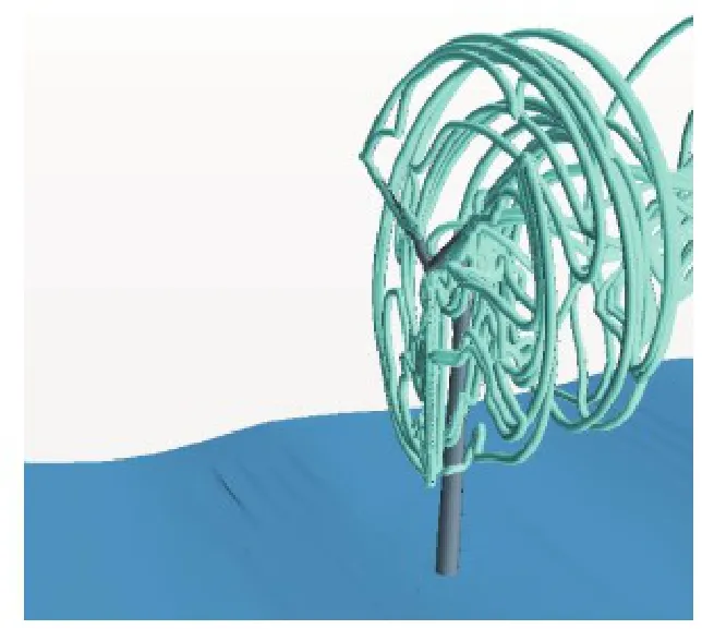
Fig.8 Isosurface of vorticity behind wind turbine
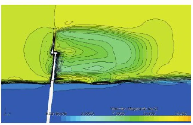
Fig.9 Flow field of the FOWT
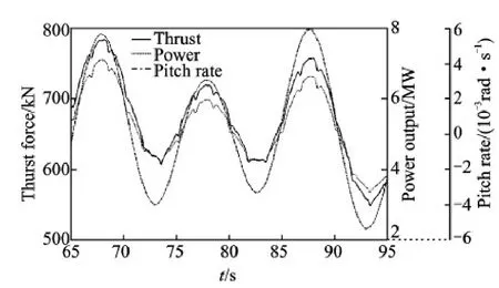
Fig.10 Time-histories of power and thrust force
After 200 s simulation,the dynamic responses of wind turbine performance and typical platform motions are presented in Table 5.The power output varies from 62.5% to 135.2% compared with the normal condition.The variation of power is larger than those of thrust force,that is,the power output is more sensitive than the thrust force to platform motions.And the mean value of power output from wind turbine deceases by 1.7%,which is likely due to the smaller effective area for the rotor to receive wind power when the platform pitches.Because of the thrust force acting on the top of the tower,the platform always pitches to the upwind direction in order to offset the capsizing moment induced by the thrust force.Accordingly,the platform surges from 10.5 m to 14.2 m,and the equilibrium position is 12.3 m from the initial location.It is also due to the thrust force which has to be offset by the tension of mooring lines.
The compassion among thrust force,wave force and tower wind force is plotted in Fig.11.All the force components respond as a period of 10 s,equaling to the wave period.The wind force acting on tower is smaller than that on the other components,just about 1/20 of the mean thrust force.The wave force has the same order of magnitude with the thrust force,but the amplitude of wave force variation is larger than those of thrust force.It can be seen that the tower force exists periodic fluctuation with a period of 10/3 s,which equals to the 1/3 of the blade rotation.When a blade passes through the tower,the wind force acting on tower drops by 80% from the normal value.
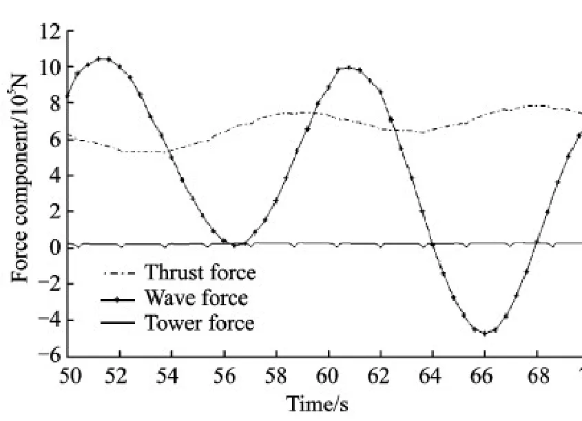
Fig.11 The comparison of force components acting on FOWT
4 Conclusions
Free-decay tests show that the surge motion predicts a lower frequency than FAST result,and the regular wave test indicates that the dynamic ranges of the platform motions are narrower than that predicted by NREL-FAST.The difference may be due to the potential flow theory used in FAST,which has no contribution in determining the non-linearity of the platform motions.
The coupled aero-hydro simulation reveals that the dynamic response of wind turbine performance and platform motions all vary in the same frequency as the inlet wave.During platform motion,the power output of wind turbine is more sensitive than the thrust force.The average value of power deceases by 1.7%,probably due to the decreasing effective rotor area.
Comparison between each force component shows that wave force has the same order of magnitude with thrust force,while the thrust force is relatively stable than the wave force.Owing to the thrust force acting on the hub center,the equilibrium pitch angle of platform is-4.8°and the equilibrium position of surge is 12.3 m,which performs to offset the capsizing moment and horizontal force.
The power and thrust force of FOWT increase when the floating platform pitches to the upwind position,while the aerodynamic loads decrease as the pitch motion reverses direction.This can be explained by the variation of angle of attack for each blade section when the FOWT system experiences pitch motion.
Acknowledgements
This work was supported by the National Basic Research Program of China (″973″Program) (No.2014CB046200) and the Specialized Research Fund for the Doctoral Program of Higher Education (No.20120073120014).
References:
[1]JONKMAN J M.Dynamics of offshore floating wind turbines-model development and verification[J].Wind Energy,2009,12(5) : 459-492.
[2]JONKMAN J M,MATHA D.Dynamics of offshore floating wind turbines-analysis of three concepts[J].Wind Energy,2011,14(4) : 557-569.
[3]JONKMAN J M,SCLAVOUNOS P D.Development of fully coupled aeroelastic and hydrodynamic models for offshore wind turbines[C]∥ASME Wind Energy Symposium Reno.Nevada,USA:[s.n.],2006.
[4]REN N,LI Y,OU J.Coupled wind-wave time domain analysis of floating offshore wind turbine based on computational fluid dynamics method[J].Journal of Renewable and Sustainable Energy,2014,6(2) : 23106.
[5]QUALLEN S,XING T,CARRICA P,et al.CFD simulation of a floating offshore wind turbine system using a quasi-static crowfoot mooring-line model[C].International Society of Offshore and Polar Engineers,2013.
[6]MATHA D,SCHLIPF M,CORDLE A,et al.Challenges in simulation of aerodynamics,hydrodynamics,and mooring-line dynamics of floating offshore wind turbines [M].National Renewable Energy Laboratory,US Department of Energy,Office of Energy Efficiency and Renewable Energy,2011.
[7]KARIMIRADM,MOAN T.Effect of aerodynamic and hydrodynamic damping on dynamic response of spar type floating wind turbine[C]∥Proceedings of the European Wind Energy Conference EWEC2010.Warsaw:[s.n.],2010.
[8]KVITTEM M I,BACHYNSKI E E,MOAN T.Effects of hydrodynamic modelling in fully coupled simulations of a semi-submersible wind turbine[J].Energy Procedia,2012,24: 351-362.
[9]JONKMAN J,MUSIAL W.Offshore code comparison collaboration (OC3) for IEA wind task 23 offshore wind technology and deployment[R].National Renewable Energy Laboratory (NREL),Golden,Co.,2010.
[10]JONKMAN J,BUTTERFIELD S,MUSIAL W,et al.Definition of a 5-MW reference wind turbine for offshore system development[R].National Renewable Energy Laboratory (NREL),Golden,Co.,2009.
[11]GARZA RIOS L O,BERNITSAS M M,NISHIMOTO K.Catenary mooring lines with nonlinear drag and touchdown[D].Ann Arbor,Michigan: University of Michigan,1997.
[12]JONKMAN J M.Definition of the floating system for phase IV of OC3[M].Colorado,USA: National Renewable Energy Laboratory Golden,2010.
[13]JONKMAN J M.Dynamics modeling and loads analysis of an offshore floating wind turbine[M].[s.l.]: Pro-Quest,2007.
Mr.Wu Jun is a postgraduate student of Shanghai Jiao Tong University (SJTU),and his research interests lie in the offshore floating wind turbine.
Mr.Meng Long is a Ph.D.student of SJTU.His current research interests focus on the offshore floating wind turbine.
Mr.Zhao Yongsheng is an engineer of SJTU.His research interests are the offshore floating wind turbine.
Dr.He Yanping is a researcher and Ph.D.supervisor at SJTU,and his research interests cover the ship design and offshore floating wind turbine.
(Executive Editor: Zhang Tong)
杂志排行
Transactions of Nanjing University of Aeronautics and Astronautics的其它文章
- Gravity Effect on the First Natural Frequency of Offshore Wind Turbine Structures
- Critical Stokes Number for Gas-Solid Flow Erosion of Wind Turbine Airfoil
- Numerical Analysis on Motion of Multi-column Tension-Leg-Type Floating Wind Turbine Basement
- CFD-Based Load Calculation Method for Monopile Support Configuration of Offshore Wind Turbine
- Simulation of SLD Impingement on Wind Turbine Blade Airfoil
- Improvement of Mechanical,Dynamic-Mechanical and Thermal Properties for Noil Ramie Fiber Reinforced Polyethylene Composites
