Gravity Effect on the First Natural Frequency of Offshore Wind Turbine Structures
2016-05-12MaHongwangChenLongzhuDepartmentofCivilEngineeringShanghaiJiaoTongUniversityShanghai200240ChinaReceived26October2015revisedDecember2015acceptedJanuary2016
Ma Hongwang,Chen LongzhuDepartment of Civil Engineering,Shanghai Jiao Tong University,Shanghai 200240,P.R.China (Received 26 October 2015; revised 4 December 2015; accepted 5 January 2016)
Gravity Effect on the First Natural Frequency of Offshore Wind Turbine Structures
Ma Hongwang*,Chen Longzhu
Department of Civil Engineering,Shanghai Jiao Tong University,Shanghai 200240,P.R.China (Received 26 October 2015; revised 4 December 2015; accepted 5 January 2016)
Abstract:The fatigue limit state is critical for most offshore wind turbine.To minimize the development of fatigue damage,dynamic amplification of the response must be avoided.Thus,it is important to ensure that the first natural frequency of the offshore wind turbine does not coincide with the excitation frequencies related to wind turbine and wave loadings.For evaluating the self-gravity influence on the first natural frequency of wind turbine support structures,the offshore wind turbine system vibration is modeled using an Euler-Bernoulli beam with axial force and horizontal force.Real data from five wind turbines available in the market are considered.The sizes of wind turbines vary from 2.3 MW to 6 MW,and subsequently,the heights of tubular steel towers vary from 83 m to 100 m.Results indicate that the average influence of gravity on the first natural frequency is nearly 1.8%.The first natural frequency is considered ranging from 1P (rototor frequency) to 3P (blade passing frequency).The design procedure requires an accurate evaluation of the first natural frequency.From this perspective,the first natural frequency is reduced since gravity needs to be considered for the design of offshore wind turbine support structures,especially when the first natural frequency of the offshore wind turbine is close to the lower limit,rotor frequency 1P.
Key words:offshore wind turbine; the first natural frequency; gravity; Euler-Bernoulli beam
CLC number: TM614Document code: AArticle ID: 1005-1120(2016)01-0095-07
* Corresponding author,E-mail address: hwma@ sjtu.edu.cn.
How to cite this article: Ma Hongwang,Chen Longzhu.Gravity effect on the first natural frequency of offshore wind tur
bine structures[J].Trans.Nanjing Univ.Aero.Astro.,2016,33(1) : 95-101.
http: / /dx.doi.org/10.16356 /j.1005-1120.2016.01.095
0 Introduction
Offshore windturbines have the potential to be a significant contributor to global energy production,due to the vicinity of the high quality wind resource to coastal energy loads[1-2].Currently,most offshore wind turbines are installed in shallow water on bottom-mounted substructures.Monopiles are often adopted as foundations for offshore wind turbines[3].
The offshore wind turbines are exposed to several types of external loadings,especially predominant wind and wave actions.Every offshore structure has to withstand almost 109load cycles during life time of 20 years[4].Due to the large number of load cycles in a short time,the fatigue limit state has been found to be critical for most offshore wind turbines.To minimize the development of fatigue damage,dynamic amplification of the response must be avoided[4-5].Therefore,the important point is that the first natural frequency of the wind turbine does not coincide with the excitation frequencies related to wind and wave loadings.
For an offshore wind turbine including foundation,three classical design approaches have been defined for a three-bladed wind turbine[6]:
(1) Soft-soft design,where the tower including foundation frequency is less than 1P (rotor frequency),as well as the frequencies related to the dominant wave action.
(2) Soft-stiff design,where the tower frequency lies between the frequencies 1P and 3P (blade passing frequency) for three bladed turbines.
(3) Stiff-stiff design,where the tower frequencyis higher than the blade passing frequencies 3P (for three bladed turbines).
To capture the maximum power at every wind speed,variable speed turbines are gaining market share from constant speed turbines[7].The design approach can be redefined,as illustrated in Fig.1.
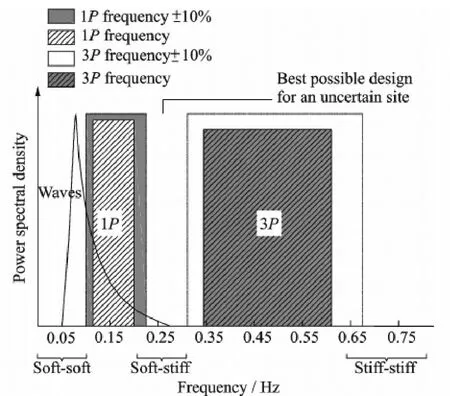
Fig.1 Diagram of allowable frequency range and excitation frequencies
It is evident that,stiff-stiff approaching requires a very stiff foundation leading to an expensive design.Although it is possible to design a soft-soft structure with the first natural frequency below the rotor frequency.In general,less steel is required for a soft-soft structure.However,for offshore wind turbines the lower bound of 1P range usually lies around the peak of the wave spectrum,where the energy in the waves is the largest.To design a soft-soft offshore wind turbine support structure,the first natural frequency must be well below the wave frequencies,and the soft-soft approach may be critical.Hence for conventional offshore wind turbines,resonance avoidance is often achieved by using the soft-stiff design approach[8-9].
The National Renewable Energy Laboratory (NRFL) 5 MW wind turbine is illustrated in Fig.1,with a minimum rotational speed at the cut-in wind speed of 6.9 r/min and the maximum rotational speed of 12.1 r/min,considering 10% engineering error.Its frequency interval is relatively narrow,ranging from 0.22 Hz to 0.31 Hz[10].
It is necessary to accurately calculate the natural frequencies for wind turbine support structures in design phrase.Currently,there is few study related to offshore wind turbine frequencies considering selfgravity of turbine,tower and part pile foundation.In order to accurately calculate the natural frequencies of wind turbine support structures,this paper analyzes gravity influence on the first natural frequency of offshore wind turbines,and analyzes the variation of earthquake load and direct wind load on the tower due to natural frequency variation.
1 Motion Equation and Boundary Conditions
1.1Equation of motion for transverse vibrations
Here,the offshore wind turbine system vibration is modeled using an Euler-Bernoulli beam[11],with axial and horizontal forces as shown in Fig.2.The bending stiffness of the beam is EI,which is fixed to the foundation.The beam has a top mass with rotary inertia J and mass M.This top mass is used to idealize the rotor and blade system.The mass per unit length of the beam is m.In this model the turbine tower is assumed to be fixed at the depth below the original mudline.The fixity depth is determined such that it produces a specified lateral displacement and rotation at the mudline that matches that of the pile embedded in the true soil profile[12].The force P1is a constant compressive axial load P = Mg,and the force q is the unit gravity load of the tower.The axial force distribution p(y) is

where p(0) = P1+ mL,p(L) = P1,L is the length of the support structure.
The equation of motion for transverse vibrations of an offshore wind turbine is given by

where x(y,t) is the transverse deflection of the beam,E the Young's modulus,I the moment of inertia,m the mass per unit length,and p(y) the axial compressive force.
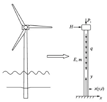
Fig.2 Structural dynamics beam model for offshore wind support structure
For any mode of vibration,the lateral deflection x(y,t) may be written in the form of

where X(y) is the modal deflection,h(t) the harmonic function of time t.If w denotes the circular frequency of h(t),one has

and the eigenvalue problem of Eq.(2) reduces to the differential equation

The four boundary conditions are at y =0,and

At y = L,and


Without loss of generality,the following dimensionless quantities are introduced
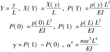
Then Eq.(5) simplifies in the dimensionless form as follows

Then the boundary conditions Eqs.(6)—(9) are simplified in the dimensionless form as follows
At Y =0 and

At Y =1,and

The dimensionless mode shape differential Eq.(10) is linear with variable coefficients and may be solved by the method of Naguleswaran[13].The power series solution sought is

where the coefficients an +1(c) are the functions of the undermined exponent c.X(Y,c) is substituted into the mode shape differential equation and the coefficients are chosen from the recurrence relationship

Y(X,c) will satisfy the mode shape differential Eq.(10) when provided that c is a root of the indicial equation

The four power series solution functions are
The coefficients of the solution functions are
The general solution of the mode shape differential equation is

where C1,C2,C3and C4are the constants of integration.
1.2Frequency equations
The boundary conditions of Eqs.(11),(12) may be utilized to eliminate two of the constants of Eq.(20) integration,C1= C2= 0.Substituting X (Y) = C3G(Y) + C4H(Y) in the boundary conditions Eqs.(13),(14),the frequency equation for this boundary condition is
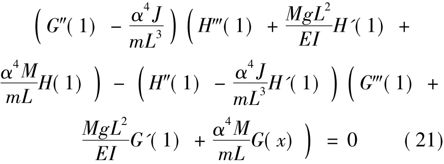
The natural frequencies can be obtained by solving Eq.(21) for α.Denoting the solution of Eq.(21) as αj,the actual natural frequencies of the system can be obtained

2 Numerical Examples
2.1Gravity influence on the first natural frequency
In this paper,the real data from five wind turbines available in the market are considered.The size of wind turbines varies from 2.3 MW to 6 MW,and subsequently,the height of tubular steel tower varies from 83 m to 100 m.The properties of wind turbines are listed in Table 1.Finally,the first two frequencies are calculated using the proposed method and the results are provided in Figs.3,4,respectively.As expected,the natural frequency decreases when the gravity influence is considered.The maximum decrease rate of the first natural frequency is 1.87% for the 3.0 MW wind turbine,and the minimum decrease rate of the first natural frequency is 1.76% for the 2.3 MW wind turbine.It is indicated that the decrease rate of the first natural frequency for 2.3 MW to 6 MW wind turbines is nearly 1.8%.Considering the allowance value of the first natural frequency should be located in narrow ranges,the upper and lower limit values for 5 MW wind turbine,are 0.31 Hz and 0.22 Hz,respectively[9].The upper limit value is only 40.9% larger than the lower one.From this perspective,the first natural frequency is reduced due to the fact that the gravity needs to be considered for designing offshore wind turbine support structures,especially for the design of the first natural frequency of offshore wind turbine close to the lower limit 1P.Fig.4 shows that the gravity has few influences on the second frequency of the multi-MW offshore wind turbines.

Table 1 Structural properties of wind turbines model
2.2Gravity influence on wind load nominal value on tower
Based on the Load Code for the Design of Building Structures (GB 50009-2012 )[14],the horizontal wind load nominal value is calculated by

where wkis the wind load nominal value,μsthewind load shape,μzthe wind pressure height coefficient,w0the basic wind speed at a height of 10 m,z the height of the offshore wind turbine tower,and βzthe wind-induced vibration factor.It does not need to consider the frequency for calculating w0,μsand μz,which means it only needs considering βzvariation to the frequency when considering gravity influence on the wind load nominal value.βzis calculated according to GB 50009-2012 standard,with and without considering gravity influence respectively.
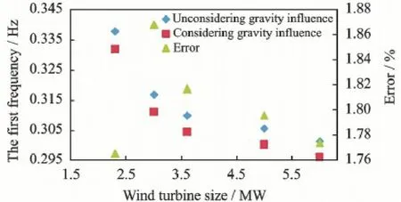
Fig.3 The first natural frequency with and without considering gravity influence
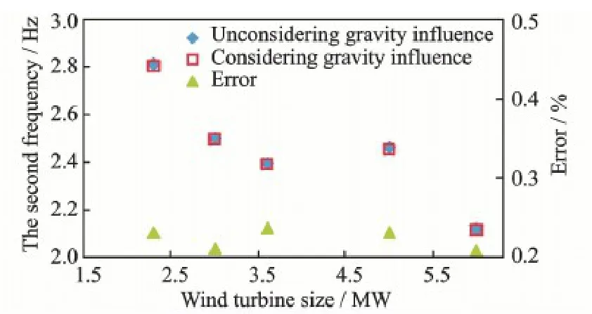
Fig.4 The second frequency with and without considering gravity influence
Table 2 shows the gravity influence on the windinduced vibration factor,indicating that the gravity has little influence on the wind-induced vibration factor,which also means the gravity has little influence on the wind load on the tower.

Table 2 The wind-induced vibration factor
2.3Gravity influence on horizontal seismic load
The seismic load is calculated according to Anne C of IEC 61400-1[15],only considering the first tower bending mode,nacelle and 50% of the tower mass is concentrated at the tower head,the ground acceleration shall be evaluated for a 475-year recurrence period.
According to the Seismic Design of Buildings Code (GB 50011-2010 )[16],the design response spectrum is expressed as
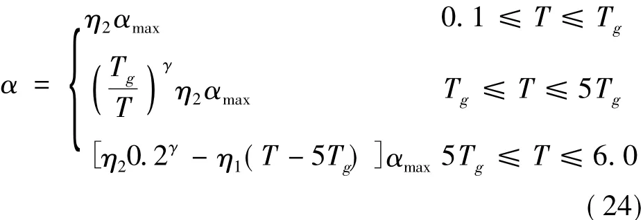
where αmaxis the maximum design earthquake parameter,Tgthe character period of the site,and T the period of the offshore wind turbine structure.η1,η2and γ are calculate by Eqs.(25)—(27)


where ξ is the damping ratio of offshore wind turbine.It was assumed that the seismic precautionary intensities of the offshore wind turbine sites are 7 and 8.Correspondingly,the maximum design earthquake parameters are αmax= 0.23,0.45,respectively.Tg= 0.9,ξ= 0.01.The seismic load of offshore wind turbines in Table 1 can be seen in Table 3.Table 3 shows that gravity influence on the horizontal seismic load is within 2.4% for the selected offshore wind turbines at the seismic precautionary intensities of 7 and 8.This is mainly because the gravity slightly influences the natural frequencies.The influences of gravity on the horizontal seismic load and wind load on tower can be ignored.Corresponding to the maximum design parameter αmax= 0.23,0.45,the maximum earthquake accelerations are 0.1 g and 0.2 g[16],respectively.The horizontal seismic load of offshore wind turbines with 8 degree seismic precautionary intensity are approximately twotimes that of 7 degree seismic precautionary intensity seismic load.

Table 3 Horizontal seismic load of offshore wind turbines
3 Conclusions
A simple model of an offshore wind turbine on amonopile foundation has been considered with the aim to analyze the gravity influence on the first natural frequency.The offshore wind turbine system vibration is modeled using an Euler-Bernoulli beam with axial and horizontal force.Based on the research results,it is indicated that the average influence of gravity on the natural frequency is nearly 1.8%,and there is few influence of gravity on the second frequency.Considering that the first natural frequency should lies between 1P and 3P,which is a relatively narrow range,the design procedure requires an accurate evaluation of the first natural frequency.From this perspective,the first natural frequency is reduced due to gravity need to be considered for design of offshore wind turbine support structures,especially for the first natural frequency of the offshore wind turbine close to the lower limit 1P.
The research results also indicate that the variations of horizontal seismic load and direct wind load are very small due to the first natural frequency vibration by the gravity.So in most cases,the gravity influence on the natural frequency could be ignored for calculating earthquake and wind force.
Acknowledgement
This work was supported by the National Basic Research Program of China (″973″Program) (No.2014CB046200).
References:
[1]SCHWARTZ M,HEIMILLER D,HAYMES S,et al.Assessment of offshore wind energy resources for the united states[R].Technical Report NREL/TP,2000.
[2]LOZANO-MINGUEZ E,KOLIO A J,BRENNAN F P. Multi-criteria assessment of offshore wind turbine support structures[J].Renewable Energy,2011 (36) : 2831-2837.
[3]ANDERSEN L V,VAHDATIRAD M J,SICHANI M T,et al.Natural frequencies of wind turbines on monopole foundations in clayey soils-A probabilistic approach[J].Computers and Geotechnics,2012(43) : 1-11.
[4]SCHAUMANN P,LOCHTE S,STEPPELER S.Special fatigue aspects in support structures of offshore wind turbines[J].Materials Science&Engineering Technology,2011(12) : 1075-1081.
[5]LEBLANC C.Design of offshore wind turbine support structures[D].Aalborg,Denmark:Aalborg University,2009.
[6]POLLACK M L,PETERSEN B J,CONNELL B S H,et al.Resonance avoidance of offshore wind turbines[C]∥Proceedings of the ASME 2010 International Mechanical Engineering Congress&Exposition.[S.l.]: IMECE,2010.
[7]KÜHN M J.Dynamics and design optimization of offshore wind energy conversion systems[D].Delft,Netherland: Delft University,Wind Energy Research Institute,2003.
[8]GUPTA A,JAIN D K,DAHIYA S.Some investigations on recent advances in wind energy conversion systems [C]∥IACSIT Coimbatore Conferences.[S.l.]:[s.n.],2012.
[9]VRIES W D.Support structure concepts for deep water sites[R].Upwind WP4 D4.2.8,Final Report,2011.
[10]VAN DER TEMPER J.Design of support structures for offshore wind turbines[D].Delft: Delft University of Technology,2006.
[11]CHOPRA A K.Dynamics of structures theory and applications to earthquake engineering[M]4th Ed.Prentice Hall,Prentice-Hall International,2001.
[12]ZAAIJER M B.Foundation modeling to assess dynamic behaviour of offshore wind turbines[J].Applied Ocean Research,2006(28) : 45-57.
[13]NAGULESWARAN S.The vibration of a complete Eul-er-Bernoulli beam of constant depth and breadth proportional to axial co-ordinate raised to a positive exponent [J].Journal of Sound and Vibration,1995(2) : 311-327.
[14]Ministry of Housing and Urban-Rural Development of P.R.China.Load for the Design of Building Structures (GB 50009—2012)[S].Beijing: China Architecture &Building Press,2012.
[15]International Electro Technical Commission.Wind Turbines—part 1: Design Requirements: IEC 61400-1 [S].Switzerland,2005.
[16]Ministry of Housing and Urban-Rural Development of P.R.China.Code for Seismic Design of Buildings (GB 50011—2010)[S].Beijing: China Architecture&Building Press,2010.
Dr.Ma Hongwang is an associate professor of Shanghai Jiao Tong University (SJTU).His research interests focus on offshore wind turbine foundation and structure seismic design.
Dr.Chen Longzhu is a professor of SJTU.His research interests lie in soil and foundation,offshore wind turbine foundation,etc.
(Executive Editor: Zhang Tong)
杂志排行
Transactions of Nanjing University of Aeronautics and Astronautics的其它文章
- CFD-Based Load Calculation Method for Monopile Support Configuration of Offshore Wind Turbine
- Critical Stokes Number for Gas-Solid Flow Erosion of Wind Turbine Airfoil
- Numerical Analysis on Motion of Multi-column Tension-Leg-Type Floating Wind Turbine Basement
- Coupled Aerodynamic and Hydrodynamic Analysis of Floating Offshore Wind Turbine Using CFD Method
- Simulation of SLD Impingement on Wind Turbine Blade Airfoil
- Improvement of Mechanical,Dynamic-Mechanical and Thermal Properties for Noil Ramie Fiber Reinforced Polyethylene Composites
