Experiment and numerical simulation on the characteristics of fluid-structure interactions of non-rigid airships
2015-11-10XiaocuiWuYiweiWangChenguangHuangYubiaoLiuLinglingLu
Xiaocui Wu,Yiwei Wang,Chenguang Huang,Yubiao Liu,Lingling Lu
Key Laboratory for Mechanics in Fluid Solid Coupling Systems,Institute of Mechanics,Chinese Academy of Sciences,Beijing 100190,China
Experiment and numerical simulation on the characteristics of fluid-structure interactions of non-rigid airships
Xiaocui Wu,Yiwei Wang∗,Chenguang Huang,Yubiao Liu,Lingling Lu
Key Laboratory for Mechanics in Fluid Solid Coupling Systems,Institute of Mechanics,Chinese Academy of Sciences,Beijing 100190,China
A R T I C L EI N F O
Article history:
Accepted 18 November 2015
Available online 28 November 2015
Fluid-structure interaction Non-rigid airships
Fluid-structure interaction is an important issue for non-rigid airships with inflated envelopes.In this study,a wind tunnel test is conducted,and a loosely coupled procedure is correspondingly established for numerical simulation based on computational fluid dynamics and nonlinear finite element analysis methods.The typical results of the numerical simulation and wind tunnel experiment,including the overall lift and deformation,are in good agreement with each other.The results obtained indicate that the effect of fluid-structure interaction is noticeable and should be considered for non-rigid airships.Flowinduced deformation can further intensify the upward lift force and pitching moment,which can lead to a large deformation.Under a wind speed of 15 m/s,the lift force of the non-rigid model is increased to approximately 60%compared with that of the rigid model under a high angle of attack.
©2015 The Authors.Published by Elsevier Ltd on behalf of The Chinese Society of Theoretical and Applied Mechanics.This is an open access article under the CC BY-NC-ND license(http:// creativecommons.org/licenses/by-nc-nd/4.0/).
As a lighter-than-air aircraft,airships are important platforms for transport and observation in the air.On the basis of their hull structure configuration,airships can be classified into three categories,namely,rigid,non-rigid,and semi-rigid airships[1]. Among all types of airships,non-rigid airships with inflated envelopes are the most common.Given that airships can be easily deformed,two aspects of fluid-structure coupling issues should be considered,i.e.,the deformation of airships in flight and the influences of this deformation on the aerodynamic characteristics of airships.
Numericalsimulationisthemainapproachforanalyzingtheeffects of the fluid-structure interaction(FSI)of airships.Bessert[2]presented a coupling scheme based on the standard solvers of ABAQUS and VSAERO to investigate the nonlinear aeroelastic behavior of an airship(i.e.,CL160).The lift curve slope of the nonlinear elastic model was noticeably larger than those of the rigid and linear elastic models.Liu[3,4]numerically investigated the aeroelasticity of a nonlinear airship with consideration of its aerodynamics and structure coupling by combining a nonlinear finite element analysis(FEA)model and a computational fluid dynamics(CFD)model.The elasticity of the airship hull exerted relatively small effects on the lift.Other works[5,6]and relevant researches on airship envelopes have considered the effects of FSI[7,8].
Intheirreviewarticle,Lietal.[9]comprehensivelysummarized the effects of FSI.They noted that they could hardly draw any definitive conclusions about the influence and importance of airshipdeformationonaerodynamicsbecauseoftworeasons.First,such difficulty is caused by the differences in the models from different studies and the possible variations in the accuracies of the coupling methods used.Second,the quantitative experimental data on airships with FSI are extremely limited;the same is true for wind tunnel and flight measurement tests.Furthermore,only a few qualitative observations have been made in the literature,and such observations demonstrate that airship deformation could be approximated in the form of beam bending.
In the present study,wind tunnel test measurements are performed with a typical non-rigid airship model.On the basis of CFD and nonlinear FEA methods,a loosely coupled procedure is established for the FSI of airships.The deformation characteristics of the typical conditions of an airship are analyzed,and the variations in the overall aerodynamic characteristics caused by deformation are investigated.
A wind tunnel test with a non-rigid airship is accomplished in the low-speed wind tunnel of the China Academy of Aerospace Aerodynamics with a 3 m×3 m section(as shown in Fig.1).The length of the airship model is 2.3 m,and its maximum diameter is 0.6 m.The arrangement of the rudders follows the Y type,and the airship is fixed on the tail in the experiment.The inflow velocity is 15m/s,andtheattackangleoftheairshipvariesfrom0°to12°.The airship envelope is made of a polyvinyl chloride(PVC)thin film.
To obtain and compare the results,a loose coupling method is adopted in solving the FSI of the airship.The surface force is obtained by solving the Reynolds-averaged Navier-Stokesequations(RANS)in the commercial software FLUENT.The shear stress transport(SST)k-ωturbulence mode and an unstructured mesh with prism-type boundary layer elements are also used. The CFD method is validated by comparing its results with the wind tunnel experimental data of the LOTTE airship.The LOTTE airship is a remote-controlled solar-powered airship,which serves both as reference configuration for theoretical investigations and as a flying test bed.More details about LOTTE can be referred to Refs.[10,11].The CFD method is comprehensively explained in Ref.[12].For the structure solver,the boundary displacement is obtained by using the finite element method with consideration of the large,nonlinear deformation in ANSYS.A thin plate spline interpolation scheme is adopted as the interface to facilitate the exchange of information between the fluid and structure solvers. Figure2showsthestrategyofthefluid-structurecouplingmethod. The results in every iterative loop are convergent for each solver. The whole coupling process is considered to be convergent if the structure deformation difference between two adjacent iterative loops is less than the criterion.For each calculation condition,the iterative loops less than 100 are needed.
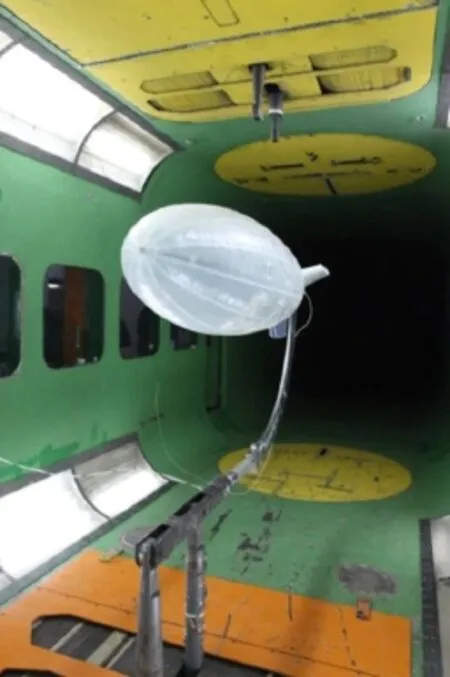
Fig.1.The soft airship model wind tunnel test.

Fig.2.The strategy of fluid-structure coupling.
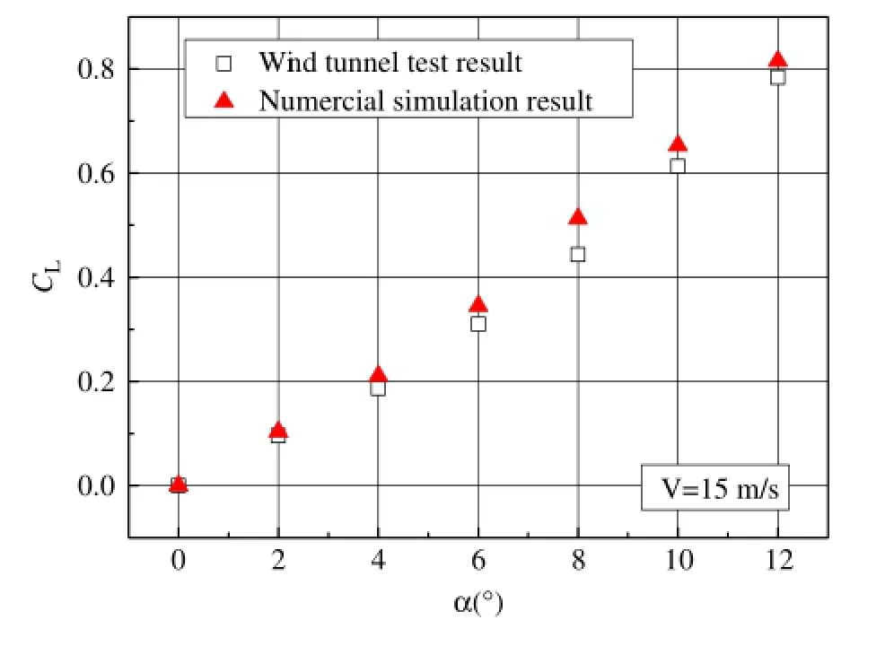
Fig.3.The lift coefficient curve of non-rigid airship model.
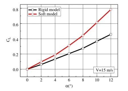
Fig.4.Lift coefficient curve compared rigid model with non-rigid model in wind tunnel test.(For interpretation of the references to color in this figure legend,the reader is referred to the web version of this article.)
Figure 3 presents a comparison of the lift coefficient curves obtained from the wind tunnel test and numerical simulation. The final result for each condition is obtained using 50 iterative loops.The computation values are in good agreement with the experimental values;the largest error is within 15%.
The lift coefficient curves in the experiments withnon-rigid and rigid models are shown in Fig.4.In this figure,the black line represents the results obtained with the rigid model,which cannot bedeformed,andtheredlinedenotestheresultsobtainedwiththe non-rigidmodelwithconsiderationofFSI.Forthenon-rigidmodel,the lift force nonlinearly increases with the attack angle under a certain wind speed.When flexible deformation is considered,the slope of the lift angle of the non-rigid model is notably higher than that of the rigid model.This observation is similar to the results obtained by Bessert[2].The lift coefficient of the non-rigid model isincreaseduptonearly60%comparedwiththatoftherigidmodel at a high angle of attack.
The errors observed in the wind tunnel experiments(Figs.3 and 4)may be due to the errors of the force measurementdevice,wind speed,and attack angle control systems.It is difficult to obtain the quantitatively accurate results due to experiment errors.Nevertheless,the whole system employed in the wind tunnel test has been successfully used in other experiments in the aerodynamicfields.Hence,theaccuracyofthevalidationprocesses for the numerical method in this study can be guaranteed.
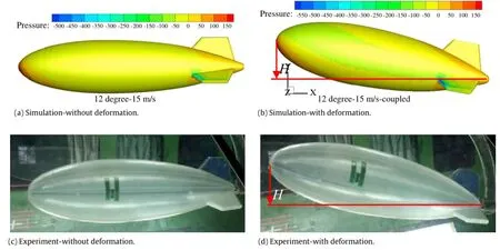
Fig.5.The pressure distribution and deformation of airship.
The surface pressure distributions of the rigid and non-rigid models under the aforementioned maximum attack angle of 12° are shown in Fig.5(a)and(b),respectively.These figures also demonstrate the deformation of a non-rigid airship.The plots showing the absence and presence of flow-induced deformation are presented in Fig.5(c)and(d),respectively.The numerical and experimental results shown in Fig.5(b)and(d)are obtained under the same flow conditions.That is,the numerically predicted deformationagreeswellwiththeexperimentalobservation.Under this large attack angle condition,an airship achieves a great overall upward lift and pitching moment.This effect results in the upward bending deformation of the airship,which becomes its primary form.Bending can cause further feedback effects. The high-pressure area increases at the bottom side,and the intensity and area of the low-pressure region both increase at the upper side.These conditions further increase the upward lift force and pitching moment.Consequently,the FSI leads to the final balanceddeformationofnotableupwardbending,accompaniedby a remarkable increase in lift force.
The maximum displacement of the airship H in the Y direction isobtainedbyperformingpixelanalysisonthephotographsshown in Fig.5(b)and(d),which shows the maximum displacements of 0.43 m and 0.45 m in the numerical and experimental results,respectively.The displacement deviation between the experiment and simulation results is about 4.4%.
ThesurfacepressuredistributionsarealsopresentedinFig.5(a)and(b).The FSI causes the stagnation point to move down,which in turn increases the pitching moment of the airship.The airship displays an upward bending deformation.The frontal area of the airship is increased,which implies that the deformation of the airship is significantly enlarged by the FSI.
Inthisstudy,alooselycoupledapproachforanalyzingtheFSIof non-rigid airships is established.The typical results obtained from the numerical simulation and wind tunnel experiment,including the overall lift and deformation,are in good agreement with each other.The maximum displacement deviation between the experiment and simulation results in the Y direction is about 4.4%. The results obtained are listed as follows:
(1)Underacertainwindspeed,theliftforceofthenon-rigidmodel increases nonlinearly at the attack angle up to approximately 60%compared with that of the rigid model at a high angle of attack.
(2)The effect of FSI is notable and should be considered for nonrigid airships.Flow-induced deformation can further intensify the upward lift force and pitching moment and cause a large deformation.The deformation of the airship is significantly enlarged by the FSI.
BothexperimentalandnumericalmethodsforsolvingFSIproblems of non-rigid airships can be further improved.For experimental method,contacting measurement sensor should be used for measuring large deformation,and better restraint condition of wind tunnel tests should be developed to reproduce the relationship of displacement and deformation of airships in flight.For numerical method,establishing closely coupling approach is an important issue to obtain unsteady responses of airships.
Acknowledgments
The authors are grateful to the National Natural Science Foundation of China(11202215 and 11332011)and the Youth Innovation Promotion Association of CAS(2015015).
[1]L.Liao,I.Pasternak,A review of airship structural research and development,Prog.Aerosp.Sci.45(2009)83-96.
[2]N.Bessert,O.Frederich,Nonlinear airship aeroelasticity,J.Fluids Struct.21(2005)731-742.
[3]J.Liu,C.Lu,L.Xue,Investigation of airship aeroelasticity using fluid-structure interaction,J.Hydrodyn.Ser.B 20(2008)164-171.
[4]J.M.Liu,C.J.Lu,L.P.Xue,Numerical investigation on the aeroelastic behavior of an airship with hull-fin configuration,J.Hydrodyn.Ser.B 22(2010)207-213.
[5]G.A.Amiryants,V.D.Grigorive,F.Z.Ishmuratov,et al.Investigations of airship aeroelasticity,in:23rd International Congress of Aerospace Sciences,Toronto,Canada,2002.
[6]K.Omari,E.Schall,B.Koobus,et al.Inviscid flow calculation around a flexible airship,in:8th Conference of Applied Mathematics and Statistics,Jaca,Spain,September 15-18,2004.
[7]C.Wang,X.Du,Z.Wan,An experimental study on wrinkling behaviours andcharacteristicsofgossamerspacestructures,Strain43(2007)332-339.
[8]W.G.Kang,Y.W.Suh,K.Woo,et al.,Mechanical property characterization of film-fabric laminate for stratospheric airship envelope,Compos.Struct.75(2006)151-155.
[9]Y.Li,M.Nahon,I.Sharf,Airship dynamics modeling:A literature review,Prog. Aerosp.Sci.47(2011)217-239.
[10]P.Funk,T.Lutz,S.Wagner,Experimental investigations on hull-fin interferences of the LOTTE airship,Aerosp.Sci.Technol.8(2003)603-610.
[11]T.Lutz,P.Funk,A.Jakobi,et al.Summary of aerodynamic studies on the lotte airship,in:4th International Airship Convention and Exhibition.Cambridge,England,2002,pp.101-110.
[12]X.C.Wu,Y.W.Wang,C.G.Huang,et al.,Aerodynamic simulation of airship ambient flows with high attack angles and analysis on turbulence models and parameters,Eng.Mech.31(2014)24-31.(in Chinese).
3 June 2015
.
E-mail address:wangyw@imech.ac.cn(Y.Wang).
http://dx.doi.org/10.1016/j.taml.2015.11.001
2095-0349/©2015 The Authors.Published by Elsevier Ltd on behalf of The Chinese Society of Theoretical and Applied Mechanics.This is an open access article under the CC BY-NC-ND license(http://creativecommons.org/licenses/by-nc-nd/4.0/).
Numerical simulation
Wind tunnel test
*This article belongs to the Fluid Mechanics
杂志排行
Theoretical & Applied Mechanics Letters的其它文章
- Anomalous friction of graphene nanoribbons on waved graphenes
- Combined modeling of cell aggregation and adhesion mediated by receptor-ligand interactions under shear flow
- Effect of viscoelasticity on skin pain sensation
- The critical pressure for driving a red blood cell through a contracting microfluidic channel
- Mechanical responses of the bio-nano interface:A molecular dynamics study of graphene-coated lipid membrane
- Effects of humidity on shear behavior of bamboo
