Optimization Study on a Single-cylinder Compressed Air Engine
2015-11-01YUQihuiCAIMaolinSHIYanandXUQiyue
YU Qihui, CAI Maolin, SHI Yan*, and XU Qiyue
School of Automation Science and Electrical Engineering, Beihang University, Beijing 100191, China
Optimization Study on a Single-cylinder Compressed Air Engine
YU Qihui, CAI Maolin, SHI Yan*, and XU Qiyue
School of Automation Science and Electrical Engineering, Beihang University, Beijing 100191, China
The current research of compressed air engine (CAE) mainly focused on simulations and system integrations. However,energy efficiency and output torque of the CAE is limited, which restricts its application and popularization. In this paper, the working principles of CAE are briefly introduced. To set a foundation for the study on the optimization of the CAE, the basic mathematical model of working processes is set up. A pressure-compensated valve which can reduce the inertia force of the valve is proposed. To verify the mathematical model, the prototype with the newly designed pressure-compensated intake valve is built and the experiment is carried out, simulation and experimental results of the CAE are conducted, and pressures inside the cylinder and output torque of the CAE are obtained. Orthogonal design and grey relation analysis are utilized to optimize structural parameters. The experimental and optimized results show that, first of all, pressure inside the cylinder has the same changing tendency in both simulation curve and experimental curve. Secondly, the highest average output torque is obtained at the highest intake pressure and the lowest rotate speed. Thirdly, the optimization of the single-cylinder CAE can improve the working efficiency from an original 21.95% to 50.1%, an overall increase of 28.15%, and the average output torque increases also increases from 22.047 5 N · m to 22.439 N · m. This research designs a single-cylinder CAE with pressure-compensated intake valve, and proposes a structural parameters design method which improves the single-cylinder CAE performance.
single-cylinder compressed air engine, experimental study, mathematical model, orthogonal design, grey relation analysis
1 Introduction*
The society of today relies to a great extent on different means of transportation. The cars that increase in numbers every day emit toxic emissions on our highways and consume huge amount of fossil fuels, but oil and gas reserves will last until 2042[1]. Consequently,unconventional energy sources must be increasingly harnessed. It is anticipated that the renewable energy may account for 20%-30% of the world energy consumption in 2100[2]. As a form of energy storage, CAEs have been used in United States and Europe since the beginning of the 20th century[3]. Because of the low efficiency of CAEs, they were not used for a long period of time. CAEs as environmentally friendly cars of the future[4]which have been promoted by companies, such as Motor Development International (MDI), Energine, and so on. MDI have been signed contracts with India, USA, Spain and other countries to build different versions of the air car[5]. The air car can travel 125 km at a speed of 68 km/h. KNOWN, et al[6],used liquid nitrogen as the working fluid for an open Rankine cycle. CHEN, et al[7], used an open cycle to analyze the process of converting expansion energy to shaft work. YADAV, et al[8], proposed the construction of compressed-air engines, which mainly consist of a pneumatic cylinder, a pneumatic solenoid valve and a crank shaft. FANG, et al[9], proposed a new hybrid compressed-air and fuel engine concept, and simulation analysis is made. DÖNITA, et al[10], presented a systematic optimization of the operation of hybrid pneumatic engines system. SCHECHTER[11]conceived a new thermodynamic cycle to capture the energy of braking in the form of compressed air. BREJAUD, et al[12], studied on heat transfer in a pneumatic hybrid engine.
Piston-type CAEs have been commonly used in high-power machines that require a high-starting torque. Compressed air is supplied intermittently instead of continuously so that the air consumption is much less than that of the rotary compressed engine[13]. Piston-type CAEs are powered by compressed air, which is stored in a tank. Instead of mixing fuel with air and burning it in the engine to drive the pistons with hot expanding gases,compressed-air engine use the expansion of compressed air to drive the pistons. Thus, in CAEs, the pressure outside of the intake valve (at the intake port) is always higher than that inside the cylinder. The intake valve must be modified to open and close at high pressures, and the cam profile must be modified to change the engine from a 4-stoke to a 2-stroke operation. Therefore, the conventional combustion engine does not applied to the CAE.
To address the high-pressure operation, a pressurecompensated intake valve is designed to replace the conventional intake valve. Because the geometry of the new intake valve can achieve force compensation, the force on the intake valve is decreased. The cam profile is designed to satisfy the CAE working principle. This study experimentally investigates the new piston-type CAE and verifies its mathematic model. To set a foundation for the study on optimization of the single-cylinder CAE, further research on its output torque characteristics is essential.
The paper is organized as follows. In section 2, the working principle of the single-cylinder CAE is described. According to the working principle, the single-cylinder CAE is designed in section 3. In section 4, the mathematical model is built about the single-cylinder CAE. To verify the mathematical model, the experimental setup is illustrated in section 5. Meanwhile, experimental results of the cylinder pressure and output torque are given. To obtain good performance, the single-cylinder is optimized in section 6. Finally, Conclusions are given in section 7.
2 Working Principles of CAE
A typical single-cylinder CAE, as shown in Fig. 1, is composed of an intake valve (1), an exhaust valve (2), a cylinder (3), a piston (4), a connecting rod (5) and a camshaft (6).
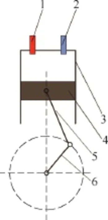
Fig. 1. Construction of CAE1. Intake valve, 2. Exhaust valve, 3. Cylinders,4. Pistons, 5. Connecting rod, 6. Crankshafts
The working principle can be described as follows.
(1) When the piston reaches its top dead center (TDC),the compressed air which is stored in compressed tank flows into the engine through the intake valve, which pushes the piston and creates movement. During the process, the exhaust valve stays closed.
(2) To make use of compressed air expansion energy, the intake valve is closed between the TDC and the bottom dead center (BDC). The piston is pushed form the TDC to BDC by compressed air expansion energy. During the process, the exhaust valve stays closed.
(3) When the piston reaches its BDC, the exhaust valve is opened. At this time, the compressed air is discharged from the cylinder. The piston moves from the BDC to TDC. During the process, the intake valve stays closed.
(4) The exhaust valve is closed before the piston reaches TDC, which results is an isentropic compression process. The work that is required to compress the air in the cylinder reduces the total work output of the entire engine cycle.
In the whole process, the compressed air energy is transferred to output shaft. The intake valve and exhaust valve opening or closing are controlled by cams which are fixed on the camshaft. Camshaft can be synchronized with the output shaft movement by timing belt.
3 Basic Model of the Working Process
To facilitate this research, the following assumptions were made.
(1) The working air of the system follows all ideal gas laws.
(2) There is no leakage in the working process, and the area of the piston rod end is too small to be considered.
(3) Supply temperature is equal to atmosphere temperature.
(4) The flow of air moving into and out of the cylinder is a stable one-dimensional flow that is, equivalent to the flow of air through the nozzle contraction.
3.1 Energy equation
Because there is no leakage in the working process,charge and discharge air do not simultaneously happen. Consequently, the energy equation for the cylinder can be illustrated by the following equation:
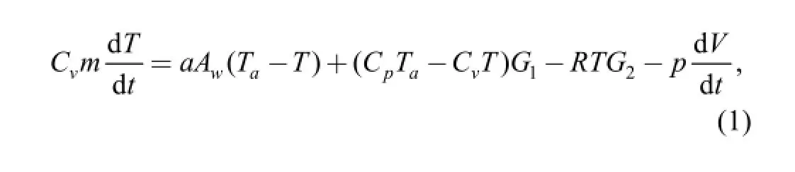
where Cvis the specific heat at constant volume, m is the air mass of cylinder, T is the air temperature of cylinder, a is the heat transfer coefficient, Awis the heat transfer area,Tais the atmosphere temperature, Cpis the specific heat at constant pressure, G1is the intake air mass flow, R is gas constant, G2is the exhaust air mass flow, p is the air pressure of cylinder, V is the air volume of cylinder.
3.2 Flow equation
According to the ratio pL/pH, the flow equation for the air that flows through a restriction is written as follows[14-15]:
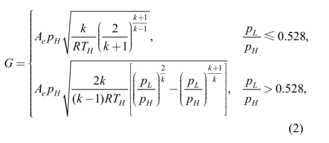
where the subscripts H and L denote the upstream and downstream compressed air, respectively. The adiabatic exponent k is set to 1.4, Aeis effective area of intake and exhaust port.
Effective area of intake and exhaust port is calculated according to passage shape, which is described later on.
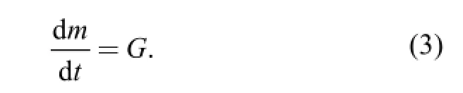
3.3 Continuity equation
From the law of mass conservation, air mass can be given as:
3.4 State equation
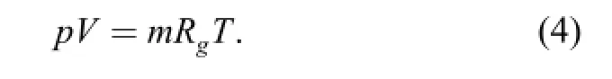
Ideal air meets the equation of the state:
3.5 Dynamic equation
The velocity of the piston is calculated from Newton's second law of motion. In this paper, the viscous friction force is considered to be a linear function of the side thrust force. The forces on the piston of the CAE are shown in Fig. 2,
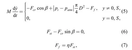
where M is the mass of the piston, rings, pin and small and end of the connecting rod, Fcris the connecting rod force, β is the connecting rod angle, piis the cylinder pressure, patmis the atmospheric pressure, D is the cylinder bore diameter,Ffis the friction force, Fstis the side thrust force, η is the coefficient of friction.
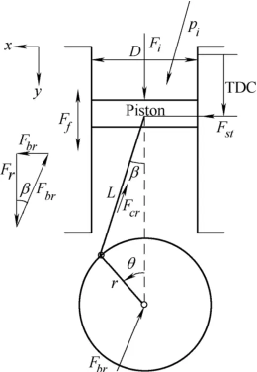
Fig. 2. Forces on the piston of the CAE
The relationship between the cylinder pressure, pi, and the output torque, Ti, is deterministic and is a function of engine geometry. This relationship is expressed as:
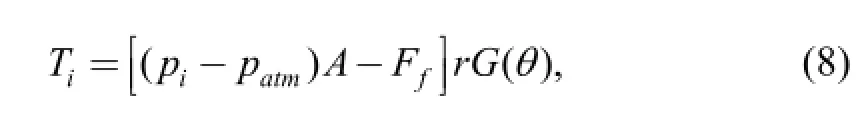
where
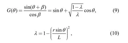
where θ is the crankshaft angular position r is the crank radius, L is connecting rod length, and A is the piston area.
The average output torque of the single-cylinder CAE is the average value of one period, which can be expressed by:
4 Design of the CAE
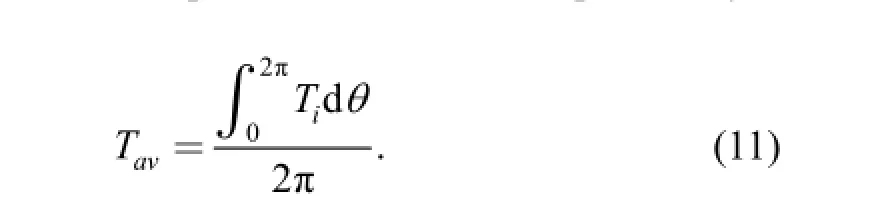
To verify the mathematical model, the single-cylinder CAE must be designed. Because the pressure outside the intake valve (in the intake port) is always higher than that inside the cylinder. To prevent air leakage, the spring preload should be greater than the inertia force of the valve, which is decided by a certain safety factor. A stronger spring was designed by HUANG, et al[13]to increase the spring preload. However, the increased spring pre-loading causes the intake valve actuator to consume more energy. This study describes a new pressure-compensated intake valve that can reduce the inertia force of the intake valve. The pressure-compensated intake valve is shown in Fig. 3. The pressure-compensated mechanism was applied in the valve stem. The O-ring rubber seal prevents leakage while the valve stem moves. The valve spring is installed on the cylinder head, which can ensure that the valve opens and closes.
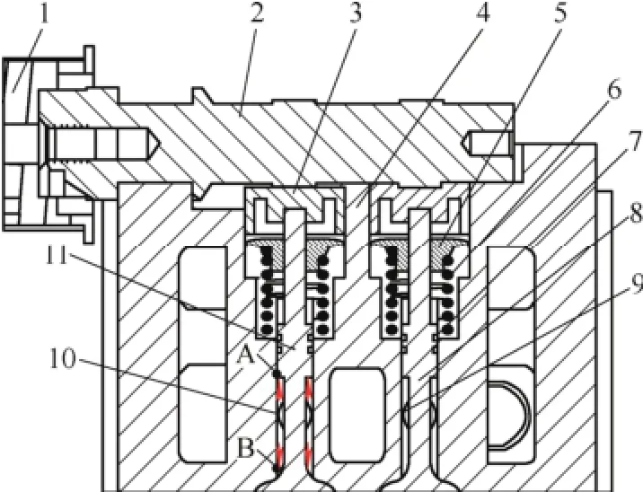
Fig. 3. A simple cross section illustration of the cylinder head1. Pulley wheel, 2. Camshafts, 3. Top cups, 4. Cylinder head,5. Valves split collect, 6. Preload springs, 7. O-ring rubber seal,8. Exhaust valve, 9. Exhaust port, 10. Intake port, 11. Intake valve
The pressurized air enters the air passages on the intake valve and is guided up to the pneumatic valve spring. Since the compressed air in the air passage acts on the intake valve, as indicated by the red arrows, the net force should be zero, and thus the valve should be pressure compensated. This means that the cylinder will be kept closed without using any valve spring and the valve diameter can now be increased in order to reduce the pressure drop. The intake valve and exhaust valve were designed as Fig. 4.
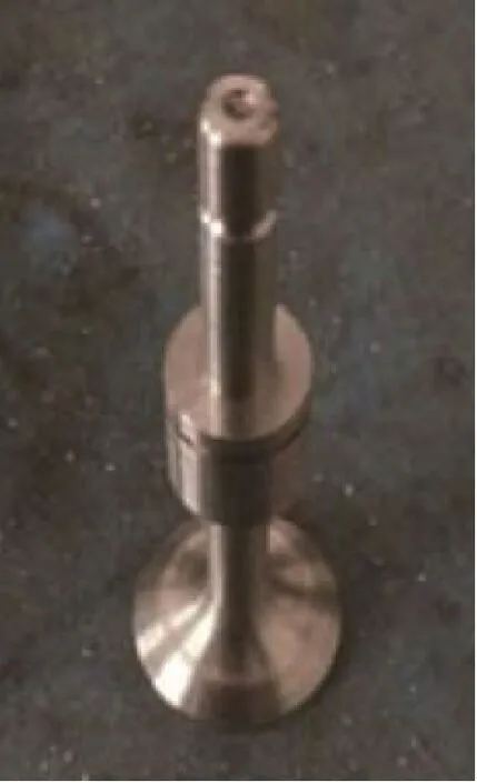
Fig. 4. Photo of intake valve
The effective areas A of the intake and exhaust valves depend on the cam profile, which is expressed by the following equation:
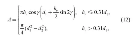
where hvis the valve lift, γ is the cone angle of the valve sealing, d1is the diameter of the flow channel, and d2is the diameter of the valve stem.
The valve lift hvis determined using the cam profile. The cam profile, which was optimized by ZHANG, et al[16], is illustrated by the following equation:
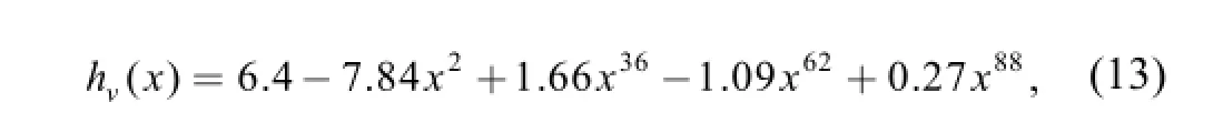
where hv(x) is the cam lift, and x=a/aB, a is the cam angle and aBis the half wrap angle. In this study, aBis equal to 62.5°. The photo of camshaft is shown in Fig. 5.
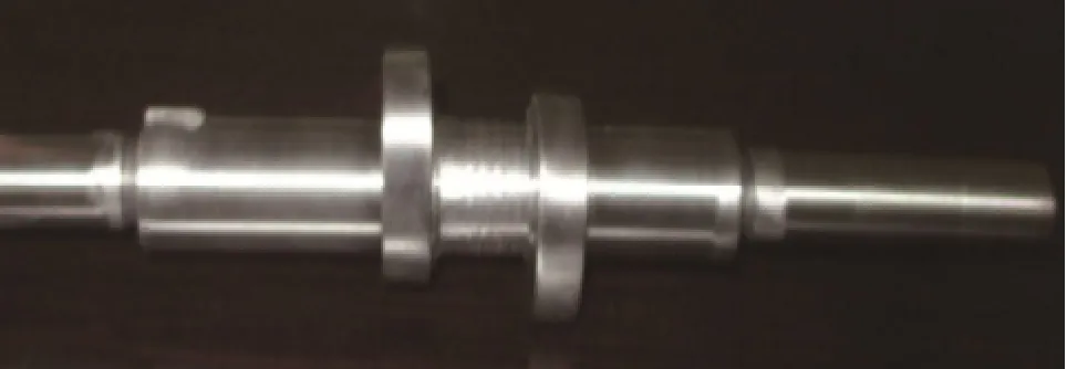
Fig. 5. Photo of camshaft
Other structures are designed referring to IC engine. Table 1 lists the specifications of the single-cylinder CAE.
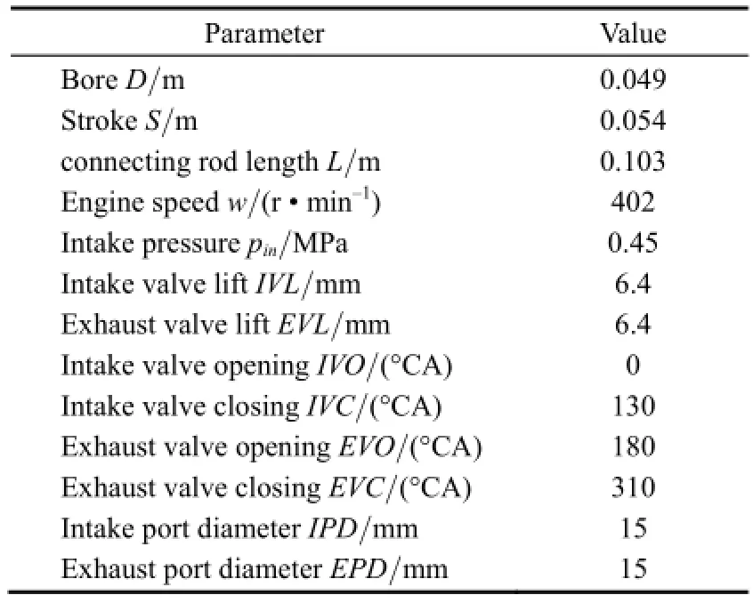
Table 1. Engine specifications
5 Experimental Verification
5.1 Experimental setup
In order to validate the single-cylinder CAE model with experimental results, the experimental was set up. In this study, the CAE was designed based on the above mechanism of the valve system. The engine was modified and connected to a compressed-air tank. Following the design of the cam profile, the intake valve opened at 0° crank angle (CA) and closed at 130° CA, whereas the exhaust valve opened at 180° CA and closed at 310° CA. The starting motor (100 A, 1.2 kW) of the engine was maintained to drive the engine if the intake valve did not open when the engine started. The intake port of the engine was connected to a compressed-air supply system that contained a 10bar air compressor (US11-10, Screw air compressor, United OSD, Germany). The pressure regulator adjusted the compressed-air pressure to the requirements of various experiments. The test bench includes an eddy current dynamometer (DWZ6, rated torque 25 N · m,maximum speed 12 kr/min, CHENGBANG, Sichuan,China) to measure the power output and the speed of the test engine. The electromagnetic brake produces a load that varies from 0 to 25 N · m. Two pressure transducers(JYB-KO-MAG1, ColliHigh) and two thermocouples were installed at the inlet and the exit of the engine to monitor the pressure and the temperature during the test. To record the cylinder pressure during the experiments, the KISTLER pressure sensor (4075A) was used to measure the absolute pressure. A gas turbine flow meter (LWQ-A/20(FL),Tianjin Sure Instrument Science & Technology Co. LTD,China) was installed at the engine inlet to record the flow rates. An absolute rotary encoder acquired the piston location in the cylinder during the engine operation. All data acquired from the experiments were transferred to a data acquisition unit for recording and further analysis. Fig. 6 shows the schematic of the compressed-air engine test bench and picture of the experimental test bench.
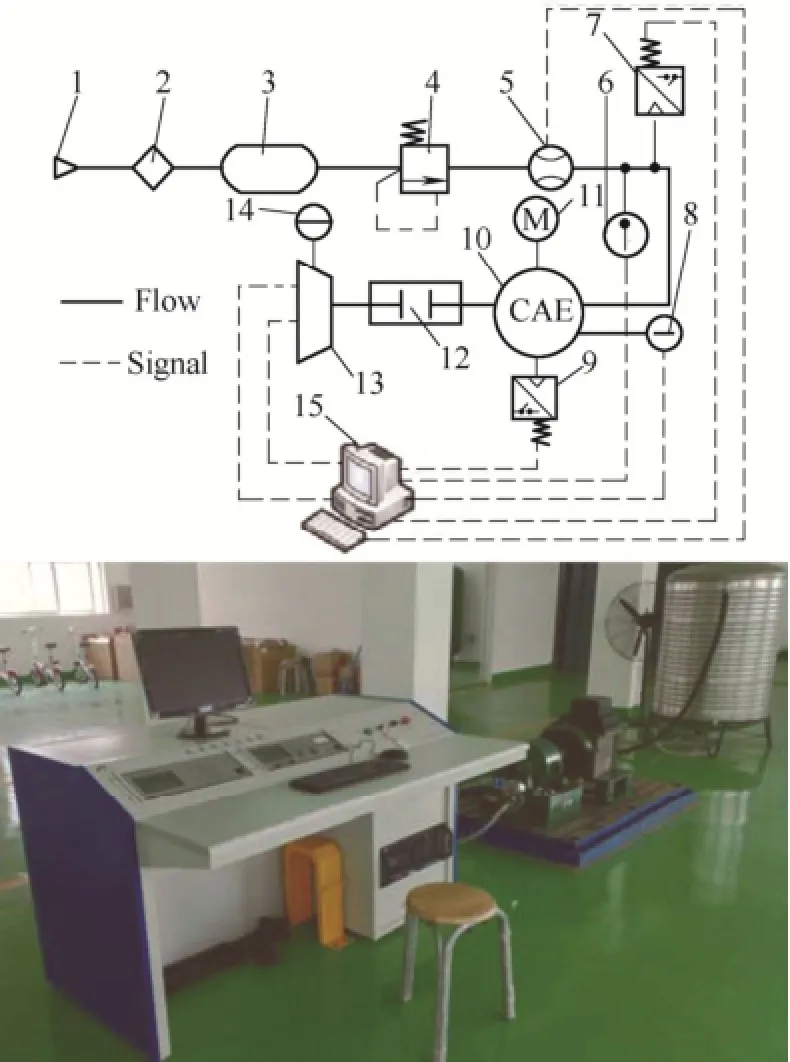
Fig. 6. Validation prototype of the CAEand its test bench1. Compressor, 2. Water filter, 3. Buffer tank, 4. Pressure regulator,5. Flow meter, 6. Inlet thermocouple, 7. Inlet prssure sensor,8. Outlet thermocouple, 9. High precision pressure sensor,10. Engine, 11. Starter, 12. Coupling, 13. Eddy current dynamometer,14. Power supply, 15. Data acquisition system
5.2 Results and analyses
1) When the intake pressure was adjusted form 0.2 MPa to 0.45 MPa, the average output torque was measured in different rotate speed. The results are shown in Fig. 7.
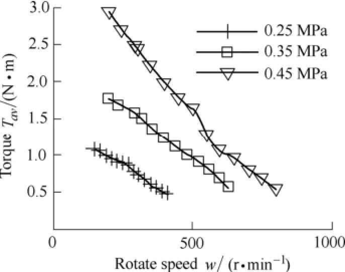
Fig. 7. Average output torque at different rotation speeds and intake pressure
The maximum average output torque 2.94 N · m was obtained when the rotate speed was 202 r/min and the intake pressure was 0.45 MPa. The highest average output torque was obtained at the highest intake pressure and the lowest rotate speed. It is obvious that the highest intake pressure provides the highest force applied on the piston and the lowest rotate speed provides the enough time to fill the cylinder.
2) To verify the mathematical model for single-cylinder CAE, the cam phase configuration of the model was made the same as Table 1, the intake pressure and the rotate speed were set to 0.45 MPa and 402 r/min, respectively. The cylinder pressure data was obtained by the simulation and KISTLER pressure sensor with crank angle as shown in Fig. 8.
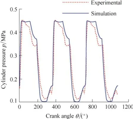
Fig. 8. Fluctuation of the cylinder pressure
As shown in Fig. 8, the simulation results are clearly consistent with the experimental results, which verify the described mathematical model. However, there are three differences between the simulation results and the experimental results.
(1) The experiment results have a lower cylinder pressure than the simulation results during the expansion process.
(2) The experiment results have higher cylinder pressure than the simulation results during the exhaust process.
(3) The cylinder pressure will decrease when the intake valve is opened during the experiment.
The main reasons for the differences are summarized as follows.
(1) There is a gap between the piston seal ring and the cylinder, the compressed air in the cylinder will leak out during the CAE working process. When the intake valve and the exhaust valve are closed, the cylinder pressure decreases. However, the simulation is based on the assumption that there is no leakage in the working process.
(2) The actual critical pressure ratio depends on the shape of the flow path in the device, the ratio will deviate from 0.528. However, the simulation is based on the assumption that the critical pressure ratio is 0.528.
(3) When the piston reaches to TDC, the intake valve was not opened. So when the piston moves to BDC, the cylinder volume will increase which lead to cylinder pressure decrease.
Other uncontrollable factors in the experiment, such as the fluctuation of the supply pressure, the heat exchange and the atmospheric temperature, also influence these differences between the simulation and the experimental results.
In the same condition, the average torque according to the simulation is 2.21 N · m, but the experimental data is 1.98 N · m. There may be several reasons for the large experimental errors. First, lubricant viscosity will increasewith the temperature decreasing. Therefore, friction force will increase during CAE operation. However, the simulation is based on fixed friction coefficient in the working process. A second reason may be that leakage will increase with the rotation speed increasing. A third reason is that the CAE is complexity system, some losses torque including bearing friction torque, valve train torque is not considered in mathematical model.
From the above analyses it is concluded that the mathematical model of the single-cylinder working cycle is reliable. But it is obvious that the average output torque is not enough to drive a car from the experimental output torque data in Fig. 7. And Cylinder pressure rarely decreased when the piston reached to BDC from the pressure curve in Fig. 8, so the power of compressed air was not used. Since the CAE must be designed to meet certain performances.
6 Optimal Design of CAE
The CAE's performance indicators include average output torque, working efficiency which represents the ratio of the ideal power output and the air power consumed[17]. The average output torque can be expressed by Eq. (10). And the working efficiency can be calculated by the following expression:
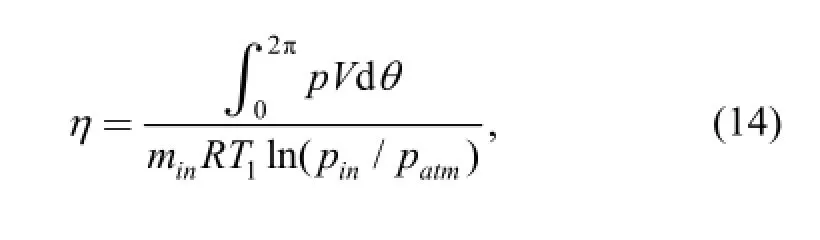
where V is the instantaneous volume of the cylinder, minis the mass of the intake air during one cycle, T1is the intake air's temperature, patmis the atmospheric pressure.
Structural parameters of the engine cannot be changed easily; in addition, the CAE's performances are affected by intake cam profile and exhaust cam profile. There are number of ways to express a cam profile mathematically[18]. In there, a five polynomial curve is chosen as follows[19]:
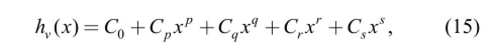
where p=2, q=2n, r=2n+2m, s=2n+4m.
Other coefficient can be solved by boundary conditions which can be expressed by following expressions:
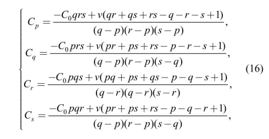
where v is seating velocity.
To meet certain performances, some structure specifications of the single-cylinder parameters are shown in Table 2.
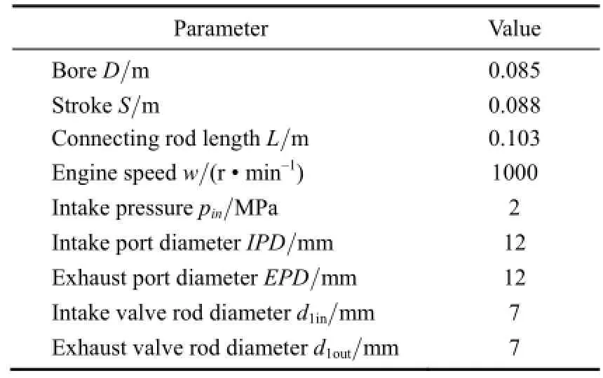
Table 2. Engine main specifications
In the light of design experience[20], the limits of these even parameters, mintake, nintake, va, mexhaust, nexhaustand vgare as Eq. (17) indicates:
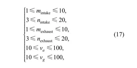
where vais intake cam seating velocity, veis exhaust cam seating velocity, subscripts intake and exhaust are the intake cam and the exhaust cam, respectively.
According to study in Refs. [21-22] and the size of the engine structure, the ranges of these even parameters, IVL,IVO, IVC, EVL, EVO and EVC are shown as Table 3.
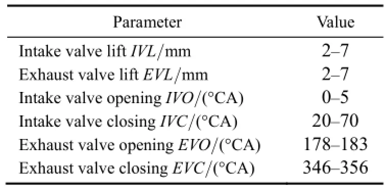
Table 3. Range of the parameters
The independent optimal of individual parameters shows that different indicators of the CAE cannot achieve optimum at the same time. So the design of the single-cylinder CAE is a multi-parameter and multi-objective optimization problem. The coupling of the parameters should be considered and an effective comprehensive evaluation method is indispensable.
To obtain representative combinations of parameters,orthogonal design[23]was used. The optimal parameter combination for expected indicators was obtained using grey relation analysis (GRA)[24-25]. In the following, GRA method was used to solve the optimal design of CAE problems.
Step 1. Based on the orthogonal array method, parameter combinations were obtained.
Step 2. Calculate the decision matrix Dij. Dijis the calculated value of the evaluation set which is formed by the indicators in Eqs. (10) and (15). i is No. i parameter combination, and j is indicator number. And then D=(Dij)N×2is decision matrix.
Step 3. Given the range of expected indicators. The vector of expected indicators is expressed as D0min=(D01min,D02min) and D0max=(D01max, D02max) whose value is set according to design requirements.
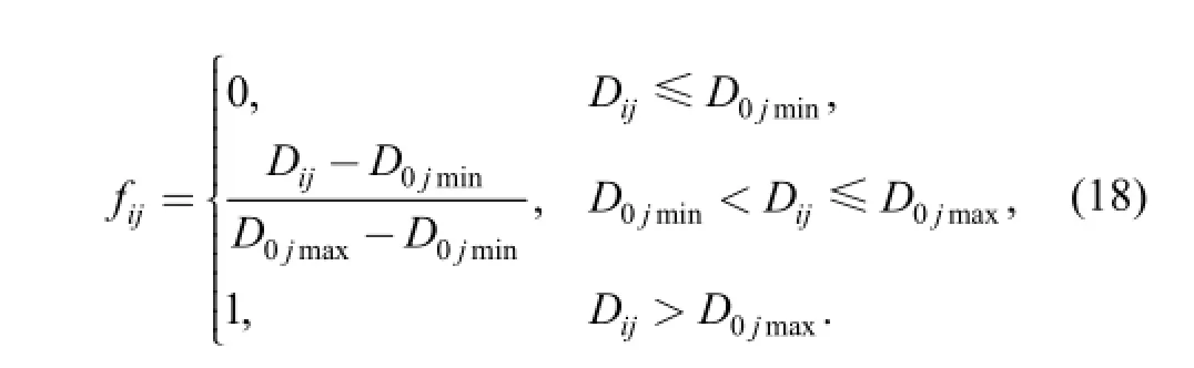
Step 4. Dimension of decision matrix. Decision matrix can be made dimensionless matrix by using the range of expected indicators, which can be expressed by following equation:
Step 5. Calculated the relational degree. The relational degree between the calculated indicators of corresponding parameter combination and the expected indicators can be calculated by:
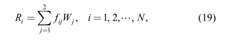
where Wjis the vector of weight, in the paper, Wj=(0.5,0.5)T.
The optimal parameter combination can be determined by the value of Ri, The bigger Riis, the more the calculated indicators are fit with the expected maximum indicators. In addition, the optimal indicators and parameter combination can be obtained.
Through simulating calculations, the optimal performance indicators and corresponding combination of parameters within the ranges are obtained and shown in Table 4 and Table 5.
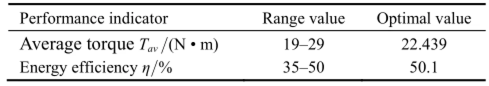
Table 4. Range of performance indicators and optimal performance indicators
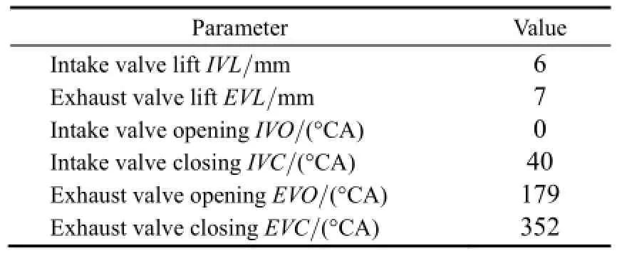
Table 5. Optimal combination of the parameters
In the same condition, above optimal combination the parameters values were replaced by Table 1 parameters value. The performance indicators Tavand η are 22.047 5 N · m, 21.95%, respectively. It is obviously that the optimization of the parameters combination can increase the single-cylinder CAE working efficiency from an original 21.95% to 50.1%, an overall increase of 28.15%,and the average output torque also increases from 22.047 5 N · m to 22.439 N · m.
7 Conclusions
This study has analyzed the working process of a single-cylinder CAE. A basic mathematical model was developed. To verify the mathematical model, a single-cylinder CAE was designed, and pressurecompensated intake valve was adopted to meet higher intake pressure. Based on the designed CAE, the experimental was built. To obtain good performance, the valve timing parameters and cam profile parameters optimization was calculated considering multi-parameter coupling and multi-performance evaluation. The conclusions are summarized as follows.
(1) The single-cylinder CAE which was designed can meet high supply pressure.
(2) The simulation results have a good consistency with the experimental results, which verifies the basic model of the single-cylinder CAE's working process.
(3) Within a certain parameter range, when the intake pressure is 2 MPa, the bore diameter is 85 mm, the stroke is 88 mm, and then the optimal output performance indicators are obtained: the single-cylinder working efficiency equals to 50.1% and average output torque is 22.439 N · m.
(4) The single-cylinder CAE working efficiency increases 28.15%, and the average output torque increases 1.8% by using the optimization of parameters combination. This research can provide theoretical supports to the new CAE design and optimization.
This research can provide theoretical supports to the new CAE design and optimization.
[1] SHAHRIAR S, ERKAN T. When will fossil fuel reserves be diminished? [J]. Energy Policy, 2009, 37(1): 181-189.
[2] QURASHI M M, TAJAMMUL H. Renewable energy technologies for developing countries now and to 2023[M]. The Islamic Educational, Scientific and Cultural Organization Press, 2005.
[3] GAIRNS J F. Industrial locomotives for mining, factory, and allied uses, part II.-compressed air and internal combustion locomotives[J]. Cassirer's Magazine, 1904, 16: 363-377.
[4] FELIX C, ANDREW P, DANIEL M K, et al. Hot deal or hot air?Lift-cycle analysis of pneumatic cars[C]//Transportation Research Board 89thAnnual Meeting, Washington DC, January 10-14, 2010,#10-0694.
[5] AFZAAL A. A pilot compressed air engine[J]. Energy & Environment, 2011, 22(8):1105-1114.
[6] KNOWLEN C, WILLIAMS J, MATTICK A, et al. Quasi-isothermal expansion engines for liquid nitrogen automotive propulsion[G]. SAE Paper 972649, 1997.
[7] CHEN Haisheng, DING Yulong, LI Yongliang, et al. Air fuelled zero emission road transportation: a comparative study[J]. Applied Energy, 2011, 88(1): 337-342.
[8] YADAV J, BHARAT R S. Study and fabrication of compressed air engine[J]. Journal of Physical Sciences, Engineering and Technology, 2011, 2(1): 1-8.
[9] FANG Q H, LIU H, CHEN Y, et al. Modeling and simulation of a new hybrid compressed-air and fuel engine concept[J]. Transactions of CSICE, 2007, 25(6): 550-555. (in Chinese)
[10] DONITA C, VASILE I, ONDER C H, et al. Modelling and optimizing two-and four-stroke hybrid pneumatic engines[J]. Proceeding of the Institution of Mechanical Engineers. Part D,Journal of Automobile Engineering, 2009, 223: 255-280.
[11] SCHECHTER M. New cycles for automobile engines[G]. SAE Paper 1999-01-0623, 1999.
[12] BREJAUD P, HIGELIN P, CHARLET A, et al. Convective heat transfer in a pneumatic hybrid engine[J]. Oil & Gas Science and Technology-Rev. IFP Energies Nouvelle, 2011, 66(6): 1035-1051.
[13] HUANG Chih-Yung, HU Cheng-Kang, YU C J, et al. Experimental investigation on the performance of a compressed air driven piston engine[J]. Energies, 2013, 6: 1731-1745.
[14] CAI Maolin. The flow characteristics of pneumatic components[J]. Hydraulic Pneumatic and Sealing, 2007, 27(2): 44-48. (in Chinese).[15] SHI Yan, CAI Maolin. Working characteristics of two kinds of air-driven boosters[J]. Energy Conversion and Management, 2011,52: 3399-3407.
[16] ZHANG Zhao, JIA Ruibin, YU Qihui, et al. Study on design criteria and methods for the valve train of the compressed-air engine[J]. Applied Mechanics and Materials, 2013, 278: 159-164.
[17] CAI Maolin, KAWASHIMA K, KAGAWA T. Power assessment of flowing compressed air[J]. Transactions of the ASME, 2006, 128: 402-405.
[18] LAMPINEN J. Cam shape optimization by genetic algorithm[J]. Computer-Aided Design, 2003, 35: 727-737.
[19] GUO Lei, CHU Chaomei, CHEN Jiaqing. Study of effects of characteristic parameters of cam profile with high-order polynomial on valve train performance[J]. Chinese Internal Combustion Engine Engineering, 2005, 26(1): 20-23. (in Chinese)
[20] SHAN Jiongji. Design and calculation of cam mechanism in IC engine[M]. Xinhua Bookstore SH: The Fudan University Press,1988. (in Chinese)
[21] YU Qihui, SHI Yan, SONG Rongzhi, et al. Dimensionless study on outlet torque characteristics[J]. J. Beijing Univ. Aeronaut Astronaut,2013, 39(9): 1233-1237. (in Chinese)
[22] XU Qiyue, CAI Maolin, YU Qihui, et al. Multi-parameter and multi-objective optimization method for air powered engine[J]. J. Beijing Univ. Aeronaut Astronaut, 2013, 39(6): 803-807. (in Chinese)
[23] CHEN J L, AU K C, WONG Y S, et al. Using orthogonal design to determine optimal conditions for biodegradation of phenantherne in mangrove sediment slurry[J]. Journal of Hazardous Materials, 2010,176: 666-671.
[24] XIA X T, LI J H. Information mining for friction torque of rolling bearing for space applications using chaotic theory[J]. Research Journal of Applied Sciences, Engineering and Technology, 2013,22(5): 5223-5229.
[25] WEI G W. GRA method for multiple attribute decision making with incomplete weight information in intuitionistic fuzzy setting[J]. Knowledge Based Systems, 2010, 23: 243-247.
Biographical notes
YU Qihui, born in 1983, is currently a PhD candidate at School of Automation Science and Electrical Engineering, Beihang University, China. He received his bachelor degree from Zhengzhou University, China, in 2007. His research interests include pneumatic blowing system.
E-mail: yqhhxq@163.com
CAI Maolin, born in 1972, is currently a professor and a PhD candidate supervisor at School of Automation Science and Electrical Engineering, Beihang University, China. His main research interests include the energy saving, measurement,simulation, and control of pneumatic system.
E-mail: caimaolin@gmail.com
SHI Yan, born in 1981, is currently a PhD candidate at School of Automation Science and Electrical Engineering, Beihang University, China. He received his bachelor degree from Yantai University, China, in 2005. His research interests include pneumatic blowing system.
E-mail: yesoyou@gmail.com
XU Qiyue, born in 1988, is currently a PhD candidate at School of Automation Science and Electrical Engineering, Beihang University, China. His research interests include pneumatic blowing system.
E-mail: mealianenko@live.com
10.3901/CJME.2015.0520.072, available online at www.springerlink.com; www.cjmenet.com; www.cjme.com.cn
* Corresponding author. E-mail: yesoyou@gmail.com
Supported by National Natural Science Foundation of China (Grant Nos. 51375028, 51205008)
© Chinese Mechanical Engineering Society and Springer-Verlag Berlin Heidelberg 2015
February 20, 2014; revised February 3, 2015; accepted May 20, 2015
杂志排行

Chinese Journal of Mechanical Engineering的其它文章
- Influence of Alignment Errors on Contact Pressure during Straight Bevel Gear Meshing Process
- Shared and Service-oriented CNC Machining System for Intelligent Manufacturing Process
- Material Removal Model Considering Influence of Curvature Radius in Bonnet Polishing Convex Surface
- Additive Manufacturing of Ceramic Structures by Laser Engineered Net Shaping
- Kinematics Analysis and Optimization of the Fast Shearing-extrusion Joining Mechanism for Solid-state Metal
- Springback Prediction and Optimization of Variable Stretch Force Trajectory in Three-dimensional Stretch Bending Process