Influence of Alignment Errors on Contact Pressure during Straight Bevel Gear Meshing Process
2015-11-01HANXinghuiHUALinDENGSongandLUOQiuping
HAN Xinghui, HUA Lin*, DENG Song, and LUO Qiuping
Hubei Key Laboratory of Advanced Technology for Automotive Components, School of Automotive Engineering,Wuhan University of Technology, Wuhan 430070, China
Influence of Alignment Errors on Contact Pressure during Straight Bevel Gear Meshing Process
HAN Xinghui, HUA Lin*, DENG Song, and LUO Qiuping
Hubei Key Laboratory of Advanced Technology for Automotive Components, School of Automotive Engineering,Wuhan University of Technology, Wuhan 430070, China
Straight bevel gears are widely applied in automotive, aerospace, chemical and many other fields as one of the most common type of gears. Currently, the researches on straight bevel gears have focused on the fields of fatigue, wear, noise and vibration, while little attention is paid to the effect of multiple alignment errors on the gear tooth wear. To study the influence of alignment errors on the gear tooth wear, a simulated model of a straight bevel gear pair is established. Then, the contact pressure on the tooth surface is analyzed under the various alignment errors according to the Archard wear relationship. The main combinations of alignment errors played vital roles on the tooth wear are investigated. The result shows that under the single alignment error, the contact pressure moves to the tooth heel and increases greatly at here when ΔP=0.1 or ΔG=0.1; when ΔE=-0.03, the contact pressure greatly increases at the tooth heel,but it obviously increases at the tooth toe when ΔE=0.03; the alignment error Δγ=1 has little effect on the contact pressure on the tooth surface. Moreover, the combination of ΔP, ΔG, ΔE<0 and Δγ is the most dangerous type among the multiple alignment errors. This research provides valuable guidelines for predicting the tooth wear under various alignment errors.
straight bevel gear, multiple alignment errors, contact pressure, wear
1 Introduction*
Straight bevel gears, as any other type of gearing, exhibit several failure modes including scoring, pitting, tooth breakage and surface wear. Among them, gear surface wear is perhaps the least studied one, partly because it takes place in a relatively long period of time to impact the functionality of a gear pair under various alignment errors. Surface wear often changes the dynamic behavior of a gear pair to result in an increase of structure-borne noise and dynamic mesh forces, which accelerate the fatigue and wear failure. So, it is of great importance to investigate the influence of alignment errors on the tooth wear of the straight bevel gear under multiple alignment errors.
By now, many researches on gear tooth wear have been carried out. Some studies[1-2]mainly investigated the tooth surface wear based on an approximate and fast wear computation methodology that combines loaded tooth contact results from a semi-analytical hypoid gear contact model with Archard's wear model. The tooth wear under the practical working conditions were studied. PARK, et al[3-4], analyzed the tooth surface wear using a numerical model that takes into account both surface roughness and lubricant properties, and revealed the contact pressure distribution on the tooth surface under various conditions of lubrication. ONISHCHENKO[5]investigated the tooth wear of spur gears considering the boundary friction, scuffing and contact temperature through the theoretical and experimental methods, and presented the wear mechanism under the contact parameters. RISTIVOJEVIC, et al[6-7],developed a mathematical model to analyze the impact of load distribution in meshed teeth, teeth geometry, and manufacturing accuracy on wear of the tooth flanks considering a larger number of impacts on the tooth flanks stress states. TUNALIOGLU, et al[8-9], studied the wear mechanism in internal gears by adapting Archard's wear equation to internal gears and writing a MATLABs programme to solve this corrected equation, and this method was verified through a fatigue and wear test equipment. Moreover, the effects of the gear tooth wear on the noise and vibration of the mechanical systems were emphasized. The wear on the tooth surface is one of the important failure modes for the gear drives. The tooth wear changes its profile, and frequently increases gear vibration and noise. INOUE, et al[10-13], studied the wear depth on the tooth surface with the contact stress, the sliding velocity,the oil film thickness based on the wear theory deduced by Soda under the lubricated condition, and investigated the relation of these factors with the noise and vibration of gears. CAO, et al[14-15], investigated the correlation between gear wear and vibration analysis. Through the comparison of noise and vibration between one normal gear and three fault gears, the relationship between gear rotation vibration error and gear mesh vibration error were analyzed. Meanwhile, many scholars have studied the gear meshing performance with alignment errors. LITVIN, et al[16],investigated the influence of alignment errors on transmission errors and the path of contact during the gear meshing process. MORIKAWA, et al[17], proposed a way to calculate the transmission errors with alignment errors. SIMON[18]analyzed the tooth contact of unloaded spiral bevel gears with alignment errors. However, it should be noted that a majority of the studies above were primarily concentrated on the gear tooth wear, while little attention was paid to how multiple alignment errors induce the gear tooth wear during the meshing process. Only the concentrated contact pressure on the gear tooth is investigated under various combinations of alignment errors, can the tooth wear be analyzed to determine the unreasonable alignment errors. Therefore, it is of great importance to investigate the influence of alignment errors on the contact pressure during the meshing process.
In this paper, a 3D FE model of the specific loaded assembling straight bevel gear pair is established. Then,based on this model, the influences of alignment errors on the contact pressure distribution are studied based on the well-known Archard wear relationship[19]as follows:
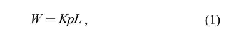
where W is the wear rate, p is the contact pressure, L is the sliding distance and K is the wear coefficient. The contact pressure of the tooth ends under the single alignment is investigated. Moreover, the most dangerous type of combined alignment errors is analyzed.
2 Design of Straight Bevel Gear Model
To obtain the accurate simulated model, the spherical involute equation is applied to draw the alveolar entity and it is represented as follows[20]:
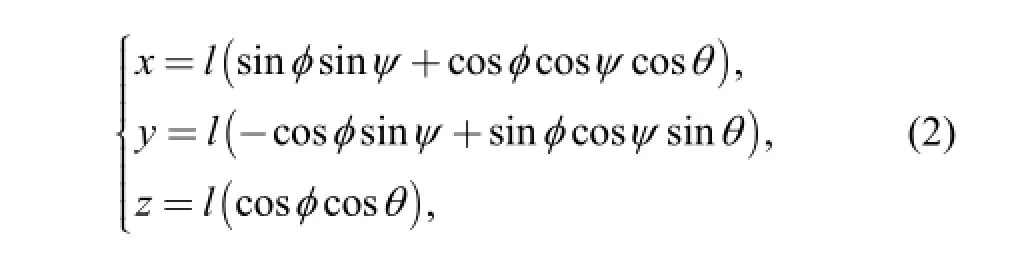
The geometry parameter of the straight bevel gear pair is shown in Table 1. According to these basic data, the alveolar entity is constructed with the modeling method in Ref. [21]. Then, the corresponding gear hub is cut to obtain the tooth space by the alveolar entity. The sample of 3D straight bevel gears and their assembly are presented in Fig. 1.
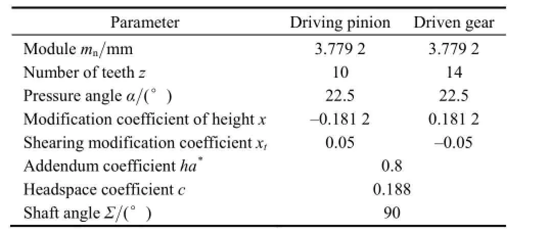
Table 1. Geometry of the straight bevel gear pair
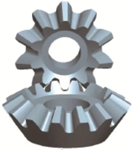
Fig. 1. 3D straight bevel gears
3 Establishment of FE Model
To establish an accurate FE model, the gears are meshed with 8-node hexahedron element(C3D8R). The material is 40Cr steel with Young's modulus E=206 GPa and Poisson's ratio µ=0.3. The friction coefficient between contact pairs is f=0.15 and the torque is T=50 N · m. The approaches are as follows.
(1) Defining Parts. The 3D geometrical models were imported into the ABAQUS software, as shown in Fig. 2. To reduce the calculation time, driving pinion and driven gear kept three teeth. To define the boundary conditions, two simplified transmission shafts were established, as shown in Fig. 3.
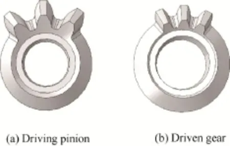
Fig. 2. Straight bevel gears with three teeth
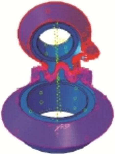
Fig. 3. Simplified shafts establishment and contact pairs definition
(2) Defining contact. The tooth surface of pinion was defined as contact surface while that of gear was defined as target surface, as shown in Fig. 3. The contacts of the simplified shafts with gears were set using the coupling command.
(3) Applying constrains. All freedom of the driving pinion was constrained except rotation around its own axis. All freedom of the driven gear was constrained. In addition,it is necessary to define the local coordinate system for the two gears to change their alignment errors.
(4) Dividing meshes. It is difficult to perform meshing because the straight bevel gear has complex profile. Thus,each tooth was divided into four subvolumes, as presented in Fig. 4. The quality of mesh was verified, as shown in Fig. 5. The result was as follows(gear-1 is the pinion and gear-2 is the driven).
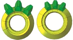
Fig. 4. Division of gear tooth
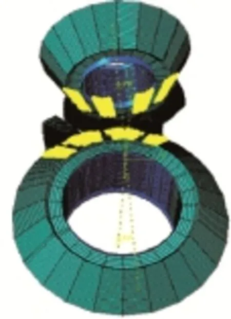
Fig. 5. Verification of mesh quality
Part instance: gear-1
Number of elements: 39 980; analysis errors: 0(0%);analysis warnings: 320(0.800 4%).
Part instance: gear-2
Number of elements: 51 303; analysis errors: 0(0%);analysis warnings: 443(0.863 08%).
4 Selection of Alignment Errors
Four types of alignment errors are defined and shown in Fig. 6, they are listed as follows:
(i)ΔP—Axial displacement of the driving pinion;(ii)ΔG—Axial displacement of the driven gear;
(iii)ΔE—Distance between two axes when the axes intersect in different planes;
(iv)Δγ—Change of crossing angle.
To investigate the influence of alignment errors on the contact pressure during the meshing process of the gear pairs, the alignment errors are considered as 0 when the gear pair is in the state of standard installation. Then, the single alignment error is changed, while the other parameters in the state of standard installation remain unchanged. The values of the single alignment error are shows in Table 2.
The principles of choosing the values are as follows: the large negative value of alignment error would result in the interferences of tooth surfaces when the value was below 0,furthermore, this condition wouldn't appear in the practical assembly of gears; when the value was much larger than 0,it would cause contact stress on tooth surfaces increasing greatly.
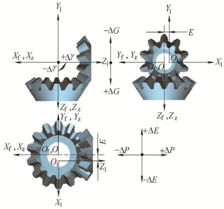
Fig. 6. Illustration of alignment errors
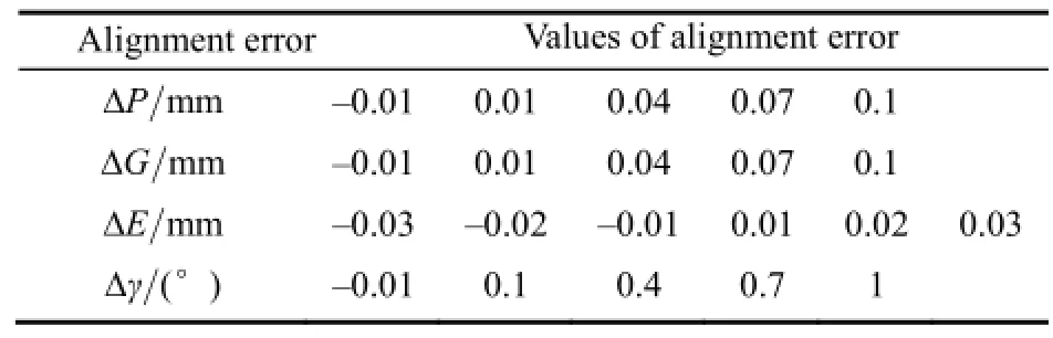
Table 2. Values of single alignment error
5 Results and Discussion
5.1 Contact pressure distributions
To investigate the contact pressure distributions during the meshing process when the gears are in the standard installation, six important meshing points are selected in a meshing cycle(driving pinion rotating 36°), they are: the point(d1) of gears just entering double-tooth meshing, the point(d2) of gears full entering double-tooth meshing, the point(d3) of gears is at the end of double-tooth meshing, the point(s1) of gears just entering single-tooth meshing, the point(s2)of gears full entering single-tooth meshing, the point(s3) of gears is at the end of single-tooth meshing. The contact area and contact pressure in the six points are shown in Fig. 7. It can be seen from Fig. 7 that the contact pressure distributions for the pinion is the same with that for the gear. The contact area along the longitudinal direction of the contact tooth pair is linear. Furthermore, it presents that in double-tooth meshing, the minimumcontact pressure appears at the point d2, but in single-tooth meshing it appears at the point s3.
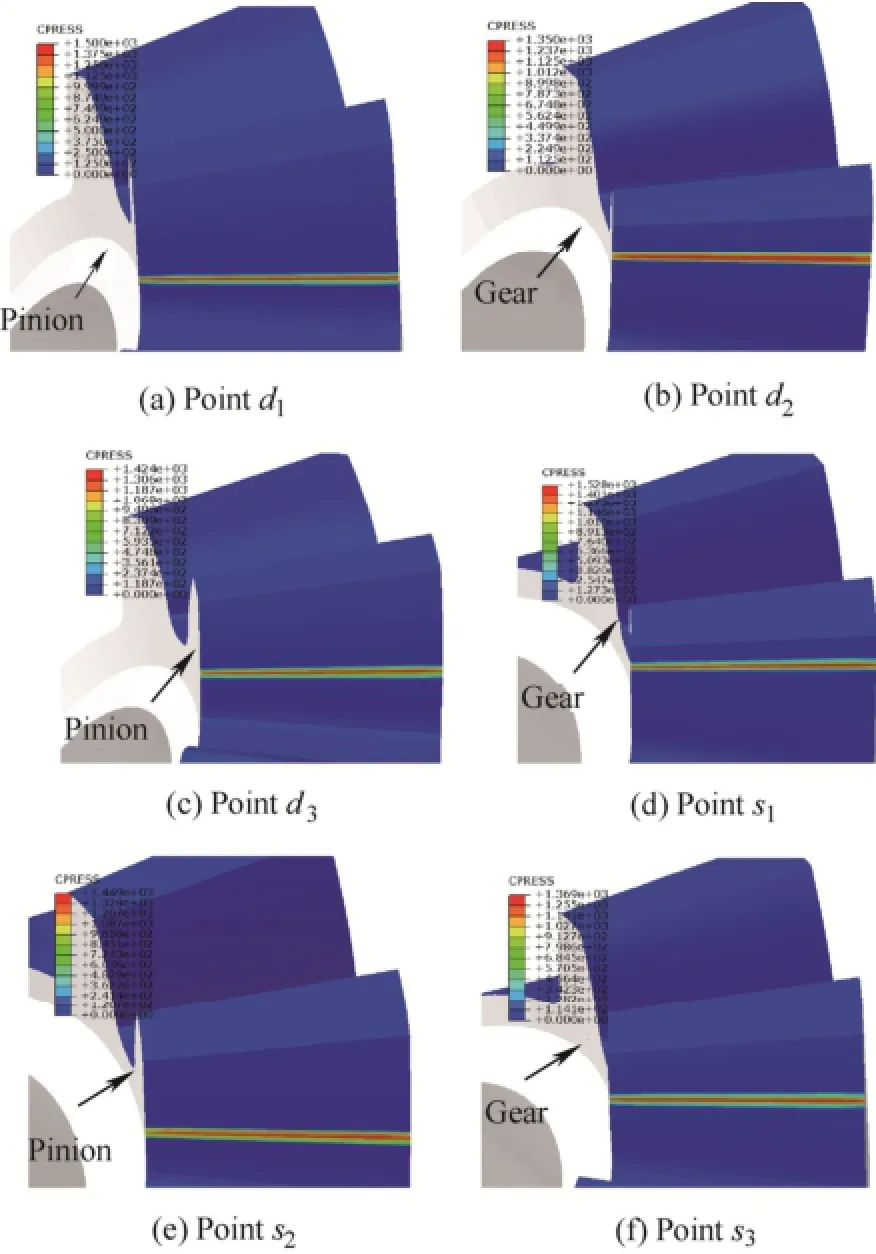
Fig. 7. Contact pressure distribution at the key meshing points for the pinion and the gear in the standard installation
The contact pressures of the tooth's ends in the standard installation are shown in Fig. 8. From Fig. 8, it can be seen that the contact pressures in the position with about 1mm distance from tooth's ends are smaller than that in the middle part of the tooth for the driving pinion or the driven gear in the whole meshing process.
To investigate the contact pressure distribution along the longitudinal direction in detail, several contact paths are chosen in the double-tooth and single-tooth meshing zones,as shown in Fig. 9. The contact pressure distributions along the longitudinal direction at the points of d1, d2, d3, s1, s2, s3are shown in Fig. 10. From Fig. 10, it may be noted that no matter the driving pinion, the driven gear, in double-tooth meshing or single-tooth meshing, the contact pressures in the position with about 1mm distance from tooth ends are smaller than that in the middle part of the tooth. This is because that the metal at the tooth ends bear smaller extrusion relative to that in the middle part of the tooth according to the theory of metal elastic-plastic deformation. Therefore, it can be concluded that the wear of tooth ends' edges is lightest in the standard installation.
5.2 Influence of alignment errors on the contact pressure during the meshing process
5.2.1 Single error
To investigate the influence of single error on the contact pressure during the meshing process, the errors values are listed in Table 2.
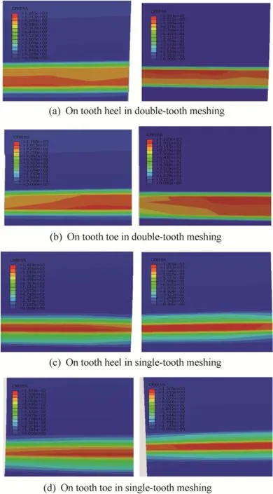
Fig. 8. Distribution of contact pressure for the pinion(left)and the gear (right) during the whole meshing process
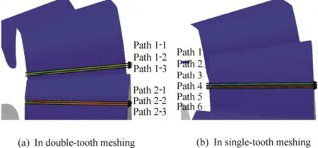
Fig. 9. Contact paths of the drive pinion along the longitudinal direction
The contact area of working tooth pair at the pitch cone is investigated. The distribution of contact pressure on tooth surface with the different single alignment error is presented in Fig. 11. It can be seen that the influence of single error on the distribution of the contact pressure for the pinion is the same with that for the gear. As shown in Fig. 11(a), the contact pressure along the longitudinal direction of the contact tooth pair is linear when the gears are in standard installation. From Figs. 11(b) and (c), it can be seen that when ΔP=0.1 or ΔG=0.1, the contact positionmoves to the tooth heel and the contact pressure at the tooth heel increases greatly. This means that the severe wear occurs at the tooth heel under this alignment error. From Fig. 11(d), it can be seen that when ΔE=-0.03, the contact position moves to the tooth heel and the contact pressure increases greatly at the tooth heel. However, when ΔE=0.03(Fig. 11(e)), the contact position moves to the tooth toe and the contact pressure increases greatly at the tooth toe. Therefore, the alignment error ΔE plays an important role on the severe wear position of gear teeth. In addition, when Δγ=1(Fig. 11(f)), the contact area changes little relative to that in the standard installation. It suggests that this alignment error(Δγ=1) contributes very little to wear.
The distribution of contact pressure on the tooth surface with the different single alignment error is presented in Fig. 12.
The influence of ΔP on the contact pressure is shown in Fig. 12(a). It can be seen that ΔP contributes very little to the contact pressure when ΔP<0, but oppositely when ΔP>0, especially in double-tooth meshing. Moreover, the contact pressure increases with increasing the value of ΔP.
The influence of ΔG on the contact pressure is shown in Fig. 12(b). From Fig. 12(b), it can be seen that when ΔG>0,ΔG affects greatly the contact pressure, but oppositely when ΔG<0. Moreover, the contact pressure increases with increasing the value of ΔG.
The influence of ΔE on the contact pressure is shown in Fig. 12(c). As shown in Fig. 12(c), no matter ΔE>0 or ΔE<0, the influence of ΔE on the contact pressure is significant; the contact pressure increases with increasing the value of|ΔE|. Moreover, the influence of ΔE on the contact pressure in double-tooth meshing is heavier than that in single-tooth meshing; furthermore, the influence of ΔE<0 on the contact pressure is greater than that when ΔE>0.
The influence of Δγ on the contact pressure is shown in Fig. 12(d). The influence of Δγ on the contact pressure in double-tooth meshing(0°-10°) is heavy, and the contact pressure increases with the increase of Δγ; however, in single-tooth meshing(10°-36°), Δγ contributes a little to the contact pressure, and the contact pressure decreases with the increasing of Δγ. Therefore, the proper increase of Δγ(for example, Δγ=0.1-0.4) can effective reduce the contact pressure and wear during the meshing process.
In summary, single error contributes much to the contact pressure and wear, resulting in the contact pressure moving to the tooth heel and aggravating wear, especially ΔP, ΔG,ΔE<0. However, ΔE>0 results in the contact pressure moving to the tooth toe and aggravating wear; the contact pressure of the tooth pair is insensitive to the alignment error Δγ.
5.2.2 Combined alignment errors
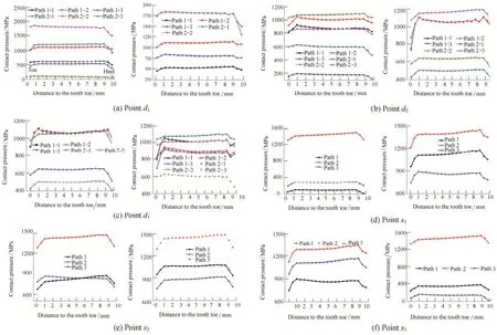
Fig. 10. Contact pressure distribution along longitudinal direction for the pinion(left) and the gear(right)
According to the analysis above, single error ΔP=0.1,ΔG=0.1, ΔE=±0.03 and Δγ=1 play an important effect on the contact pressure on the tooth surface. So, it is significant to studythe influence of combined alignment errors on the contact pressure. The values of combined alignment errors are shows in Table 3. Meanwhile, the other parameters in the state of standard installation remain unchanged.
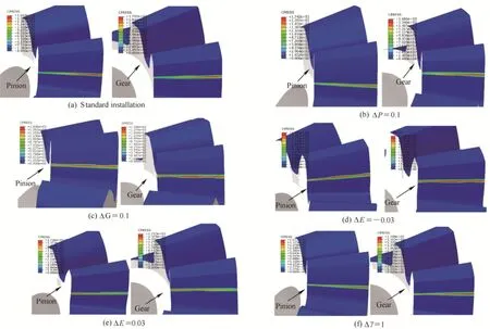
Fig. 11. Distribution of contact pressure on tooth surface for the pinion and the gear with the different single alignment error
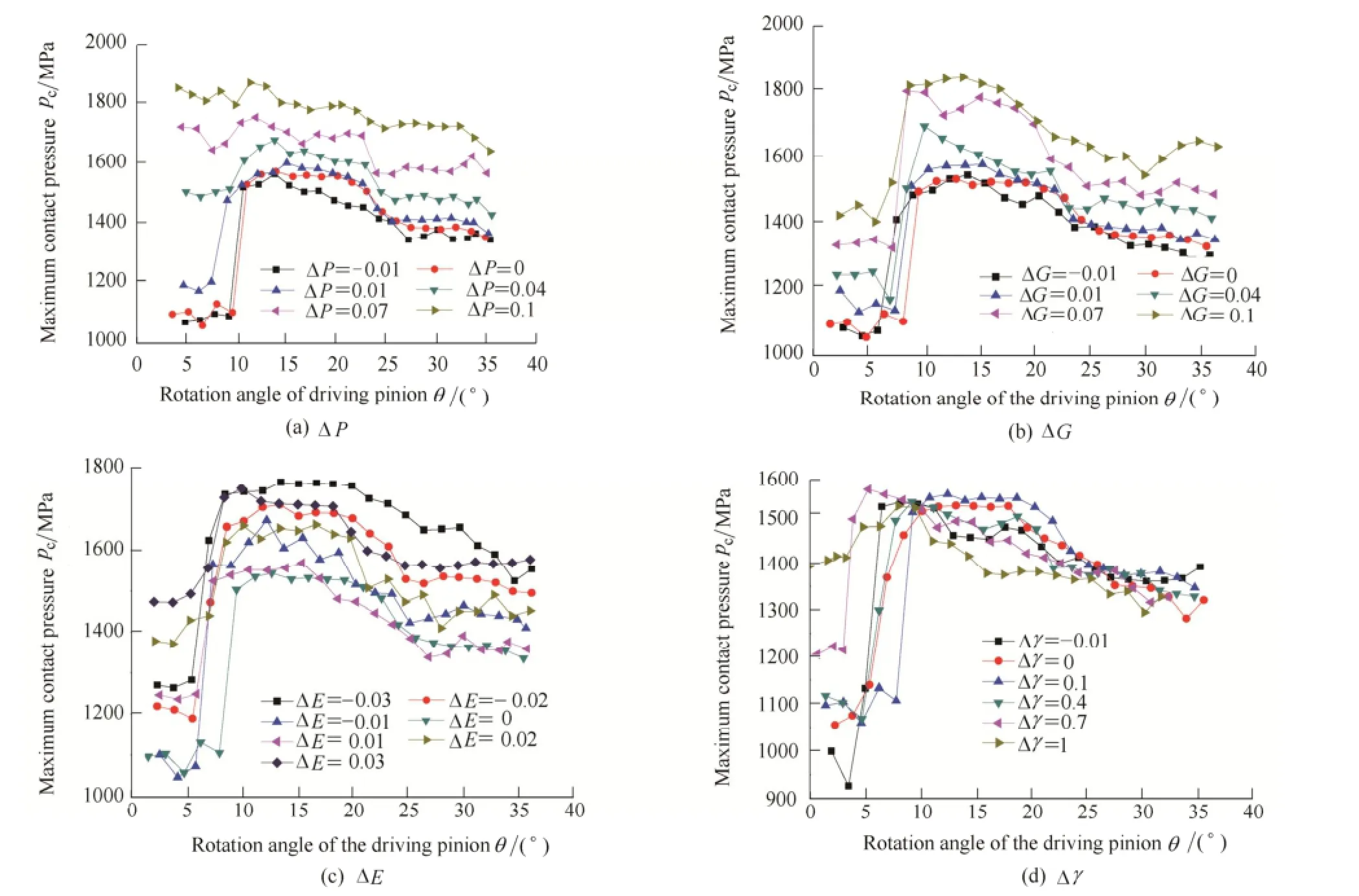
Fig. 12. Influence of single error on the contact pressure
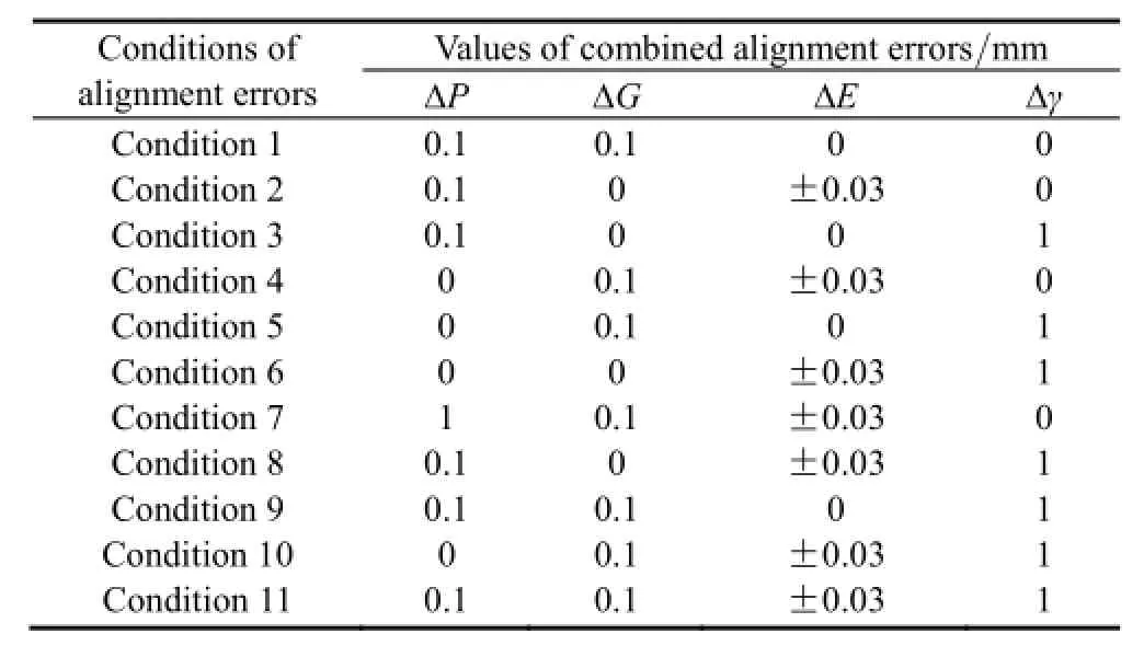
Table 3. Values of combined alignment errors
Fig. 13 shows the distribution of contact pressure on the tooth surface with two combined alignment errors. The influence of combined alignment errors on the distribution of the contact pressure for the pinion is the same with that for the gear.
As shown in Figs. 13(a), (b) and (e), it can be seen that the length of contact line along the longitudinal direction decreases significantly and the contact pressure concentrates on the tooth heels of the pinion and the gear. This indicates that the extrusion between the gear tooth surfaces under the single alignment error is accumulated under the conditions of ΔP=0.1 and ΔG=0.1, ΔP=0.1 and ΔE=-0.03, ΔG=0.1 and ΔE=-0.03. Thus the concentrated contact pressure that occurs on the tooth heels is significantly increased. This means that the wear on the tooth surface is severe under these conditions.
From Figs. 13(c), (f) and (i), it can be seen that when ΔP=0.1 and ΔE=0.03, the concentrated contact pressure on the tooth heels of the pinion and the gear is relieved; when ΔG=0.1 and ΔE=0.03, no the concentrated contact pressure exists on the tooth ends, which is similar to that in standard installation; moreover, the contact pressure concentrates on the each toe of teeth when Δγ=1 and ΔE=0.03. The reason for these is that ΔP and ΔG result in the contact pressure concentrating on the tooth heels of the pinion and the gear, but ΔE>0 causes the contact pressure concentrating on the toes of teeth; Δγ contributes very little to the contact pressure concentration. Therefore, it can be concluded that when ΔE>0 combines with ΔP or ΔG, the concentrated contact pressure on the tooth heels of the pinion and the gear is relieved and it can relieve the wear on the tooth surface. Comparing Fig. 13 with Fig. 11, it can be seen that when Δγ combines with ΔP, ΔG, or ΔE, the contact pressure, compared with that in the single error ΔP,ΔG, and ΔE, has little change on the tooth surface.
Figs. 14 and 15 show the contact pressure distribution on the tooth surface with three combined alignment errors and four combined alignment errors. As presented in Figs. 14 and 15, the influence of combined alignment errors on the distribution of contact pressure for the pinion is the same with that for the gear. It can be seen that the length of contact line along the longitudinal direction decreases dramatically and the contact pressure seriously concentrates on the tooth heels of the pinion and the gear for any combination of three alignment errors. This is because that ΔP, ΔG, and ΔE(ΔE<0) is sensitive to the contact pressure concentrating on the heel of tooth. Furthermore, they have a cumulative effect on the length of contact line. However,the contact pressure is the greatest when four alignment errors(ΔE<0) are combined. Therefore, the combination of ΔP, ΔG, ΔE<0 and Δγ is the most dangerous type of alignment errors.
In this section, the influence of alignment errors on the contact pressure in the straight bevel gear meshing is studied, the effect of ΔE>0 on the contact pressure is ignored because ΔE<0 contributes more to the contact pressure than ΔE>0. From Fig. 16(a), it can be seen that the contact pressure under the combination of ΔP=0.1,ΔG=0.1 and ΔE=-0.03 is larger than that under the single alignment error and the two combined alignment errors. However, the combination of ΔP=0.1, ΔG=0.1, ΔE=-0.03 and Δγ=1 has an important role on the contact pressure relative to the combination of ΔP=0.1, ΔG=0.1 and ΔE=-0.03 in the double-tooth meshing, but oppositely in the single-tooth meshing. This suggests that the alignment error Δγ has an important influence on the contact pressure under the four combined alignment errors, although it contributes little to the contact pressure under the single alignment error. Moreover, the contact pressure under the combination of ΔP=0.1, ΔG=0.1 and ΔE=-0.03 is larger than that under the combination of ΔP=0.1, ΔG=0.1 and Δγ=1. This means that ΔE=-0.03 enhances the effect of ΔP=0.1 and ΔG=0.1 on the contact pressure relative to Δγ=1.
From Fig. 16(b), it can be seen that the contact pressure under the combination of ΔP=0.1 and ΔE=-0.03 is larger than that under the single alignment error ΔP=0.1 or ΔE=-0.03. Moreover, the contact pressure under the combination of ΔP=0.1, ΔE=-0.03 and Δγ=1 is larger than that under the combination of ΔP=0.1 and ΔE=-0.03 in the double-tooth meshing, but oppositely in the single-tooth meshing. Under the combination of ΔP=0.1,ΔE=-0.03 and Δγ=1, the contact pressure is larger than that under the combination of ΔP=0.1, ΔE=-0.03, Δγ=1 and ΔG=0.1 in the double-tooth meshing, but under the combination of two alignment errors, the contact pressure has no obvious difference in the single-tooth meshing. This suggests that proper ΔG can reduce the effect of the combined ΔP=0.1, ΔE=-0.03 and Δγ=1 on the contact pressure.
From Fig. 16(c), it can be seen that the contact pressure under the combined ΔP=0.1 and Δγ=1 is larger than that under the single alignment error ΔP=0.1 in the double-tooth meshing. This means Δγ=1 enhances the effect of ΔP=0.1 on the contact pressure. Moreover, under the combination of ΔP=0.1, Δγ=1 and ΔG=0.1, the contact pressure is smaller than that under the combined ΔP=0.1 and Δγ=1 in the double-tooth meshing. This indicates that ΔG=0.1 can reduce the influence of the combined ΔP=0.1and Δγ=1 on the contact pressure. However, under the combination of ΔP=0.1, Δγ=1 and ΔE=-0.03, the contact pressure obvious increases relative to that under the combined ΔP=0.1, Δγ=1 and ΔG=0.1 in the double-tooth meshing. This means that ΔE=-0.03 increases the influence of the combined ΔP=0.1 and Δγ=1 on the contact pressure. Therefore, it is of great importance to group proper the alignment errors to alleviate the contact pressure.
From Fig. 16(d), it can be seen that the contact pressure under the combined ΔG=0.1 and ΔE=-0.03 is larger than that under the single alignment error. However, the contact pressure under the combined ΔG=0.1, ΔE=-0.03 and Δγ=1 is larger than that under the combined ΔG=0.1 and ΔE=-0.03 in the double-tooth meshing. This suggests that Δγ=1 intensifies the effect of the combined ΔG=0.1 and ΔE=-0.03 on the contact pressure in the double-tooth meshing. Moreover, under the combination of ΔG=0.1,ΔE=-0.03, Δγ=1 and ΔP=0.1, the contact pressure is larger than that under the combined ΔG=0.1, ΔE=-0.03 and Δγ=1 in the whole meshing process. This means some combinations of these alignment errors can induce the increase of the contact pressure on the tooth surface.
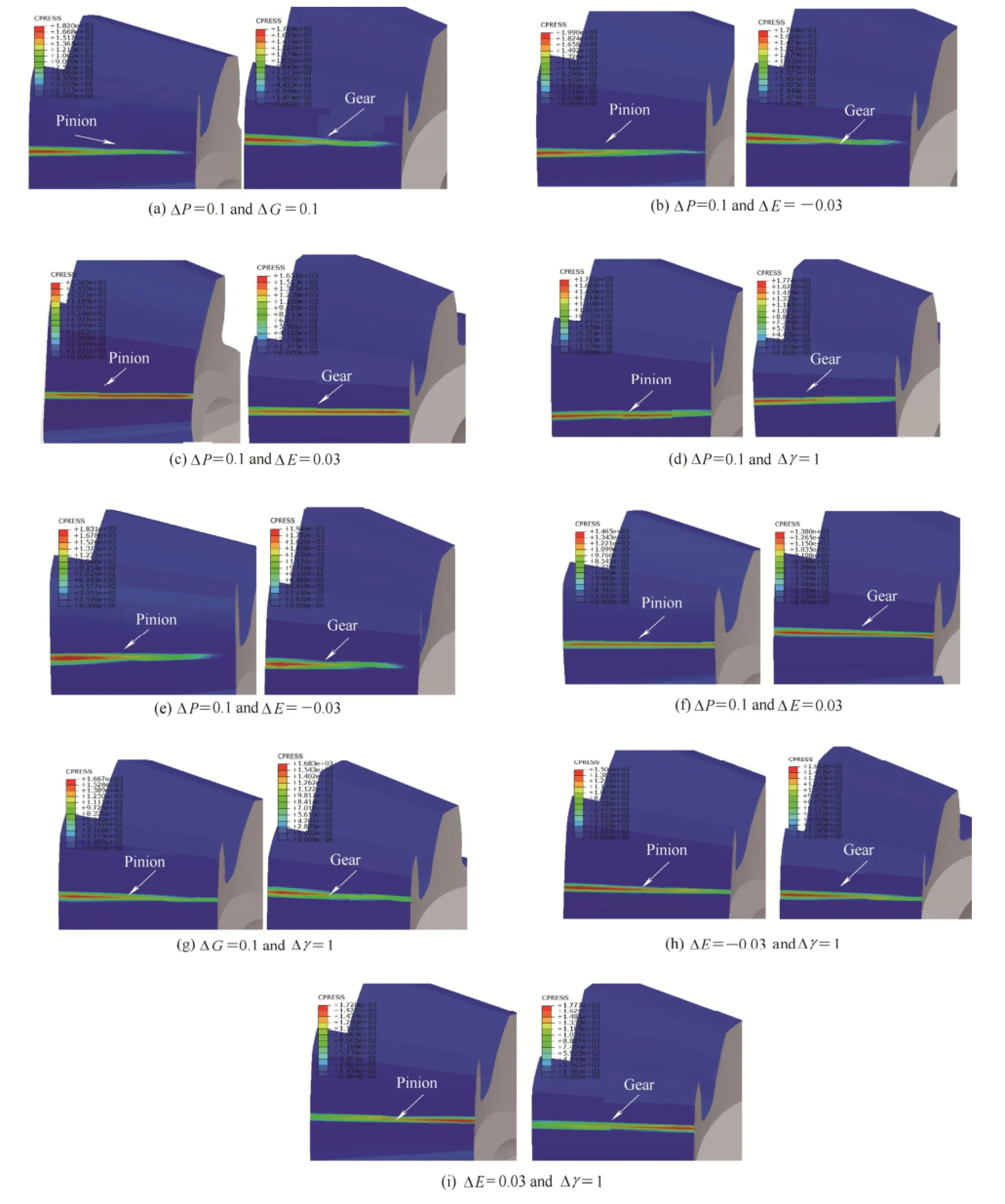
Fig. 13. Distribution of contact pressure on tooth surface for the pinion and the gear with the combined alignment errors
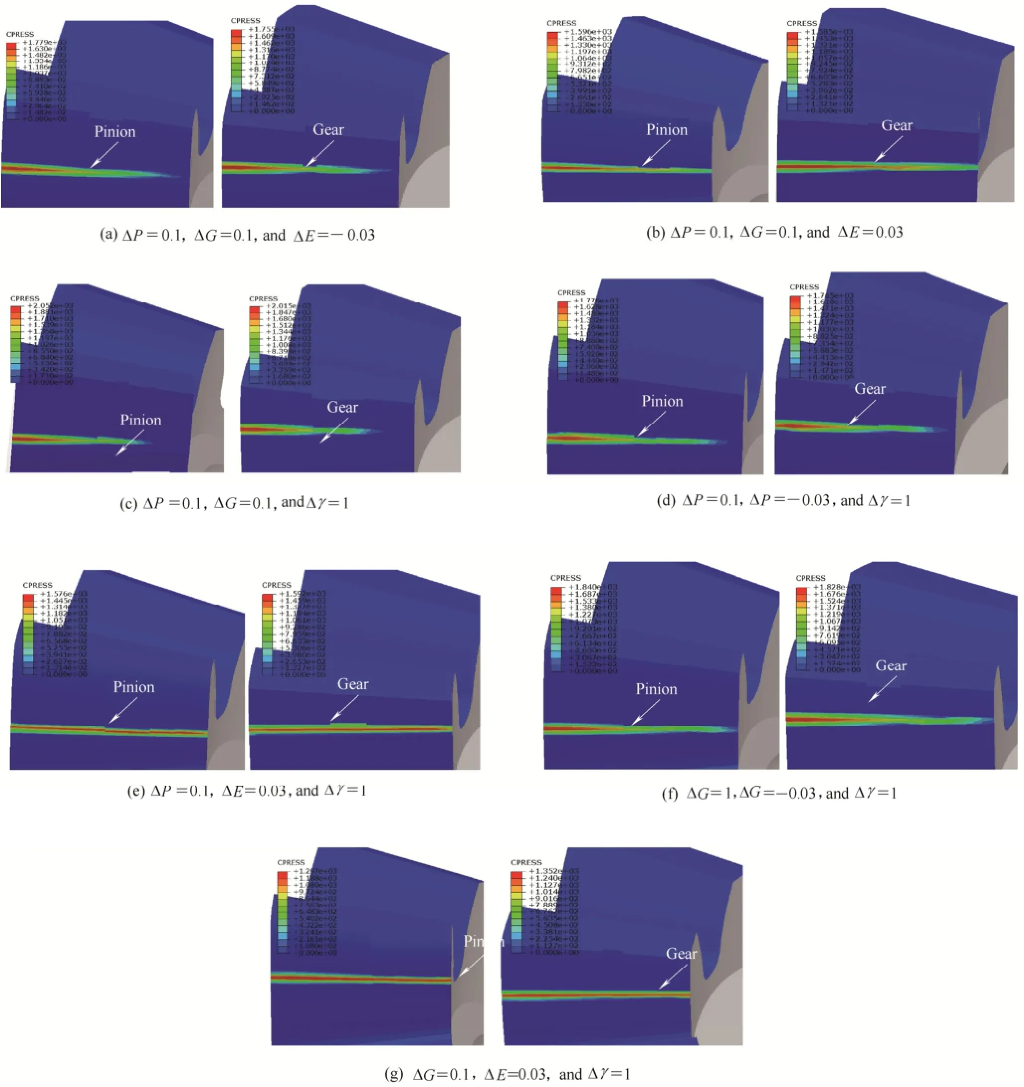
Fig. 14. Distribution of contact pressure on tooth surface for the pinion and the gear with the combined alignment errors
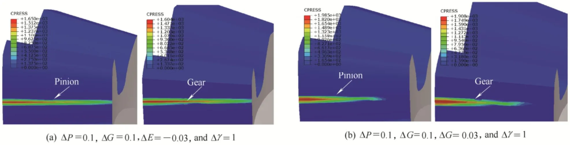
Fig. 15. Distribution of contact pressure on tooth surface for the pinion and the gear with the combined alignment errors
From Fig. 16(e), it can be seen that the combination of ΔG=0.1 and Δγ=1 results in increasing the contact pressure in the double-tooth meshing with respect to the single alignment error. Moreover, when ΔE=-0.03 combines with ΔG=0.1 and Δγ=1, the contact pressure smaller than that under the combination of ΔG=0.1 and Δγ=1 in the single-tooth meshing. However, ΔP=0.1,combined with ΔG=0.1, Δγ=1 and ΔE=-0.03, results in increasing sharply the contact pressure in the whole meshing process. This indicates that the combination of alignment errors can either increase the contact pressure or decrease it. Therefore, the different combination of alignment errors has various effects on the contact pressure,that is, a reasonable combination of alignment errors can alleviate the contact pressure during the meshing process.
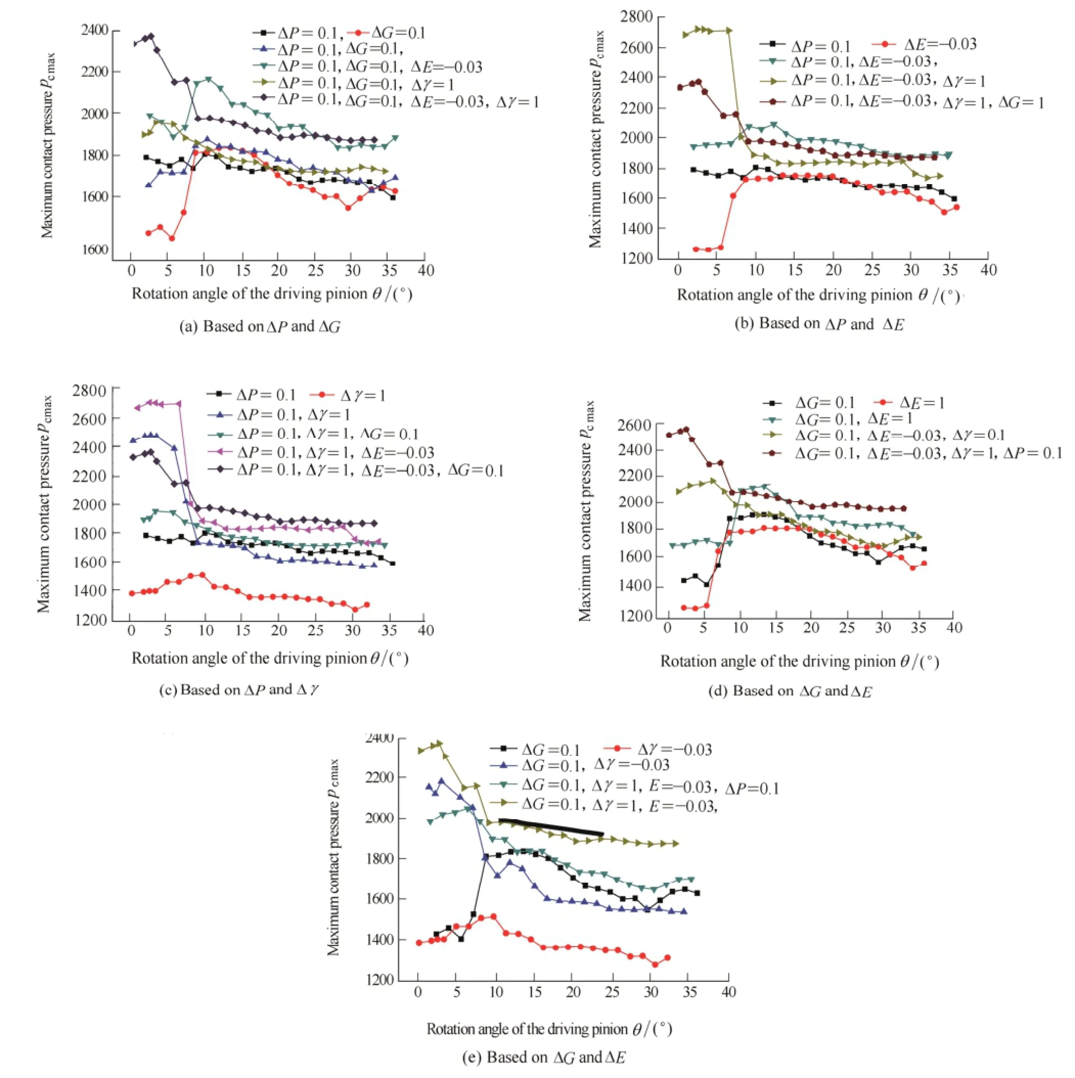
Fig. 16. Influence of combined alignment errors on the contact pressure during the meshing process
6 Conclusions
(1) Under the single alignment error, the contact pressure moves to the tooth heel and increases greatly at here when ΔP=0.1 or ΔG=0.1; when ΔE=-0.03, the contact pressure greatly increases at the tooth heel, but it obviously increases at the tooth toe when ΔE=0.03; the alignment error Δγ =1 has little effect on the contact pressure on the tooth surface.
(2) Under the two alignment errors, the severe wear occurs on the tooth heels of the pinion and the gear when ΔP=0.1 and ΔG=0.1, ΔP=0.1 and ΔE=-0.03, ΔG=0.1 and ΔE=-0.03; the contact pressure concentrates on the each toe of teeth when Δγ=1 and ΔE=0.03; under the combinations of ΔP=0.1 and ΔE=0.03, ΔG=0.1 and ΔE=0.03, no the concentrated contact pressure exists on the tooth ends; when Δγ combines with ΔP, ΔG, or ΔE, the contact pressure has little change on the tooth surface relative to that under the single error ΔP, ΔG, and ΔE.
(3) The combination of ΔP, ΔG, ΔE<0 and Δγ is the most dangerous type of alignment errors. The alignment error Δγ has a positive influence on the contact pressure under the four combined alignment errors, although it contributes little to the contact pressure under the single alignment error. Moreover, proper ΔG can reduce the effect of the combined ΔP=0.1, ΔE=-0.03 and Δγ=1 on the contact pressure.
[1] PARK D, KOLIVAND M, KAHRAMAN A. An approximate method to predict surface wear of hypoid gears using surface interpolation[J]. Mechanism and Machine Theory, 2014, 71(1): 64-78.
[2] PARK D, KOLIVAND M, KAHRAMAN A. Prediction of surface wear of hypoid gears using a semi-analytical contact model[J]. Mechanism and Machine Theory, 2012, 52(6): 180-194.
[3] PARK D, KAHRAMAN A. A surface wear model for hypoid gear pairs [J]. Wear, 2009, 267(9-10): 1595-1604.
[4] BRANDAO J A, MARTINS R, SEABRA J H O, et al. Calculation of gear tooth flank surface wear during an FZG micropitting test[J]. Wear, 2014, 311(1-2): 31-39.
[5] ONISHCHENKO V. Investigation of tooth wears from scuffing of heavy duty machine spur gears[J]. Mechanism and Machine Theory,2015, 83(1): 38-55.
[6] RISTIVOJEVIC M, LAZOVIC T, VENCL A. Studying the load carrying capacity of spur gear tooth flanks[J]. Mechanism and Machine Theory, 2013, 59(1): 125-137.
[7] PEDRERO J I, PLEGUEZUELOS M, MUNOZ M. Critical stress and load conditions for pitting calculations of involute spur and helical gear teeth[J]. Mechanism and Machine Theory, 2011, 46: 425-437.
[8] TUNALIOGLU, MERT S, TUC B. Theoretical and experimental investigation of wear in internal gears[J]. Wear, 2014, 309(1-2): 208-215.
[9] WANG B, HUA L. Computerized design and FE simulation of meshing of involute spiral bevel gears with alignment errors[C]//The 2nd International Conference on Manufacturing Science and Engineering. Advanced Materials Research, Guilin,China, April 9-11, 2011: 386-391.
[10] INOUE S, IKEJO K, NAGAMURA K, et al. A prediction method of wear on tooth surface for spur gears[C]//Proceedings of the ASME 2013 International Design Engineering Technical Conferences and Computers and Information in Engineering Conference, Oregon,USA, August 4-7, 2013: V005T11A032.
[11] CHANA K S, CARDWELL M T, SULLIVAN J S. The development of a new concept for gear teeth wear and damage detection[C]//Proceedings of the ASME Turbo Expo, v8, 2013,ASME Turbo Expo 2013: Turbine Technical Conference and Exposition, Texas, USA, June 3-7, 2013: V008T44A002.
[12] Al-TUBI IS, LONG H, ZHANG J, et al. Experimental and analytical study of gear micropitting initiation and propagation under varying loading conditions[J]. Wear, 2015, 328-329: 8-16.
[13] MURARO MA, KODA F, et al. The influence of contact stress distribution and specific film thickness on the wear of spur gears during pitting tests[J]. Journal of the Brazilian Society of Mechanical Sciences and Engineering, 2012, 34(2):135-144.
[14] CAO Y, XIE XP, LIU Y, et al. A Study of the correlation between gear wear and vibration[C]//5th China International Symposium on Tribology, Beijing, China, September 24-27, 2008: 273-277.
[15] MORALES-ESPEJEL G.E, BRIZMER V. Micropitting modelling in rolling sliding contacts: application to rolling bearings[J]. Tribology Transaction, 2011, 54(4): 625-643.
[16] LITVIN F L, FUENTES A, FAN Q, et al. Computerized design,simulation of meshing, and contact and stress analysis of face-milled formate generated spiral bevel gears[J]. Mechanism and Machine Theory, 2002, 37: 441-459.
[17] MORIKAWA K, KUMAGAI K, KOMORI M, et al. Transmission error prediction method of planetary gears taking account of alignment error[J]. Journal of Advanced Mechanical Design,Systems and Manufacturing, 2012, 6(4): 513-525.
[18] SIMON V. Computer simulation of tooth contact analysis of mismatched spiral bevel gears[J]. Mechanism and Machine Theory,2007, 42: 365-381.
[19] HAN XH, HUA L. 3D FE modelling of contact pressure response in cold rotary forging[J]. Tribology International, 2013, 57: 115-123.
[20] HUANG H L, HUA L, HAN X H. Research on the tooth modification of involute straight bevel gear[J]. China Mechanical Engineering, 2009, 20(7): 799-802.
[21] DENG S, HUA L, HAN XH, et al. Finite element analysis of contact fatigue and bending fatigue of a theoretical assembling straight bevel gear pair[J]. Journal of Central South University,2013, 20: 279-292.
Biographical notes
HAN Xinghui, born in 1979, is currently an associate professor at Hubei Key Laboratory of Advanced Technology for Automotive Components, School of Automotive Engineering, Wuhan University of Technology, Wuhan, China. He received his PhD degree from Wuhan University of Technology, China, in 2010. His research interests include advanced manufacturing technology.
E-mail: hanxinghuihlp@126.com
HUA Lin, born in 1962, is currently an professor at Hubei Key Laboratory of Advanced Technology for Automotive Components,School of Automotive Engineering, Wuhan University of Technology, Wuhan, China. He received his PhD degree from Xi'an Jiaotong University, China. His research interests include advanced manufacturing technology.
DENG Song, born in 1986, is currently a lecturer at Hubei Key Laboratory of Advanced Technology for Automotive Components,School of Automotive Engineering, Wuhan University of Technology, Wuhan, China. His research interests include advanced manufacturing technology.
E-mail: guoheng0722@126.com
LUO Qiuping, born in 1990, is currently a master candidate at Hubei Key Laboratory of Advanced Technology for Automotive Components, School of Automotive Engineering, Wuhan University of Technology, Wuhan, China.
E-mail: 13276700635@163..com
10.3901/CJME.2015.0413.041, available online at www.springerlink.com; www.cjmenet.com; www.cjme.com.cn
* Corresponding author. E-mail: hualin@whut.edu.cn
Supported by National Natural Science Foundation of China(Grant No. 51105287), and Innovative Research Team Development Program of Ministry of Education of China(Grant No. IRT13087)
© Chinese Mechanical Engineering Society and Springer-Verlag Berlin Heidelberg 2015
October 9, 2014; revised March 26, 2015; accepted April 13, 2015
杂志排行

Chinese Journal of Mechanical Engineering的其它文章
- Shared and Service-oriented CNC Machining System for Intelligent Manufacturing Process
- Material Removal Model Considering Influence of Curvature Radius in Bonnet Polishing Convex Surface
- Additive Manufacturing of Ceramic Structures by Laser Engineered Net Shaping
- Kinematics Analysis and Optimization of the Fast Shearing-extrusion Joining Mechanism for Solid-state Metal
- Springback Prediction and Optimization of Variable Stretch Force Trajectory in Three-dimensional Stretch Bending Process
- Effect of Surface Topography on Stress Concentration Factor