Kinematics Analysis and Optimization of the Fast Shearing-extrusion Joining Mechanism for Solid-state Metal
2015-11-01ZHANGShuangjieYAOYunfengLILingchongWANGLijuanLIJunxiaandLIQiang1SchoolofMaterialsScienceandEngineeringHebeiUniversityofScienceandTechnologyShijiazhuang050018ChinaKeyLaboratoryofMaterialNearnetFormingTechnologyofHebeiP
ZHANG Shuangjie*, YAO Yunfeng LI Lingchong, WANG Lijuan LI Junxia and LI Qiang1 School of Materials Science and Engineering, Hebei University of Science and Technology,Shijiazhuang 050018, China Key Laboratory of Material Near-net Forming Technology of Hebei Province,Shijiazhuang 050018, China School of Mechanical Engineering, Yanshan University,Qinhuangda 066004, China
Kinematics Analysis and Optimization of the Fast Shearing-extrusion Joining Mechanism for Solid-state Metal
ZHANG Shuangjie1,2,*, YAO Yunfeng1,2, LI Lingchong3, WANG Lijuan1,2, LI Junxia1,2, and LI Qiang2,3
1 School of Materials Science and Engineering, Hebei University of Science and Technology,Shijiazhuang 050018, China
2 Key Laboratory of Material Near-net Forming Technology of Hebei Province,Shijiazhuang 050018, China
3 School of Mechanical Engineering, Yanshan University,Qinhuangda 066004, China
Dynamical Joining of the solid-state metal is the key technology to realize endless hot rolling. The heating and laser welding method both require long joining time. Based on super deformation method, a 7-bar and 2-slider mechanism was developed in Japan,and the joining time is less than 0.5 s, however the length of each bar are not reported and this mechanism is complex. A relatively simple 6-bar and 1-slider mechanism is put forward, which can realize the shearing and extrusion motion of the top and bottom blades with a speed approximately equal to the speed of the metal plates. In order to study the kinematics property of the double blades, based on complex vector method, the multi-rigid-body model is built, and the displacement and speed functions of the double blades, the joining time and joining thickness are deduced, the kinematics analysis shows that the initial parameters can't satisfy the joining process. Hence, optimization of this mechanism is employed using genetic algorithm(GA) and the optimization parameters of this mechanism are obtained, the kinematics analysis show that the joining time is less than 0.1 s, the joining thickness is more than 80% of the thickness of the solid-state metal, and the horizontal speeds of the blades are improved. A new mechanism is provided for the joining of the solid-state metal and a foundation is laid for the design of the device.
endless rolling, solid-state metal, dynamical joining mechanism, kinematic, optimization, genetic algorithm
1 Introduction*
The traditional hot rolling process is discontinuous[1], the hot billets are rolled to intermediate billets by the rough mill, and then rolled by the fishing mill, hence, the productivity is low. In the endless rolling process, the intermediate billets are welded together between the rough and fishing mill, and then continuously travel form the fishing mill[2], therefore, the endless rolling process is continuous rolling. Compared with traditional rolling,endless rolling have some excellent advantages, such as solving the discontinuous rolling, improving the stability of the microstructure and properties, increasing the rolling yield and production efficiency, ensuring the strip shape etc,hence, endless rolling is confirmed as one of the frontier technologies in hot strip rolling[3].
Endless rolling is divided two classes, one is endless strip production process(ESP)[4-5], called semi-endless rolling[6-7], and the other is intermediate billets are joined together between rough and fishing mills. The investment of ESP is great and is more disadvantageous to reform the old casting and rolling line[8]. The heating and upset joining[9], and laser welding[10]are two of the joining technologies. Since these methods both require a relatively long joining time, the joining machine must travel a long distance with the rough bars, thus larger equipment is necessitated[11-13], hence, it is hard used for the old rolling reforming.
More recently, the joining method of the solid-state metal has captured researchers' great attention. Based on super-deformation joining theory, KENJI, et al[14-15], and JONGSUB, et al[16], designed a simple apparatus, and adopted in POSCO steel company, the joining time is very quickly(in less than 0.5 s), this dynamical joining mechanism demands 7-bar and 2-slider to realize the joining movement,the mechanism is complex relatively and the physical dimension are not reported. JINWOO, et al[17], studied the joining strength by uniaxial tension testing. KANG[18]developed a profile mould used for the joining of the intermediate billets, however, no references about the application of this method are reported and this method is also need a dynamical joining mechanism. ZHANG[19]invented a mould by fast shearing-extrusion used for the solid-state metal joining, and Q345 steel are joined together successfully in the lab. DAI, et al[20]studied this process,the joint strength, the tensile strength, yield strength and elongation are close to the matrix's, the corresponding ratio is more than 90%. Unfortunately, the solid-state metal is static in this study, hence, a dynamic joining mechanism is indispensible which can be adopted in the endless rolling.
In this paper, a simple 6-bar and 1-slider mechanism is put forward, and the kinematic function is deduced based on complex vector method[21], the optimization of this mechanism is performed using GA[22]. In section 2, the 6-bar and 1-slider linkage mechanism is introduced and the joining principle is described. Then in section 3, the multi-rigid-body model of the dynamical joining mechanism is established and the kinematic function is deduced. In section 4 the optimization of this mechanism is performed. In section 5, a calculation example is given,followed by discussions and conclusions.
2 Dynamical Joining Mechanism
The dynamic joining mechanism for solid-state metal is shown in Fig. 1. It mainly consists of 6-bar and 1-slider. O and D are the frame, top blade J can slide along JH and connected with BJ, bottom blade H is fixed at the end of AH. When the driving bar AI rotates counterclockwise with the angular speedω, the top and bottom blade will move closed together or farther apart. AI is also connected to the pendulum shaft IC via a lever CDE, so that rotation of AI is converted to a back-and-forth motion of the two blades. When overlapped solid-state metal plates enter the joining mechanism shown in Fig. 1(a), AI is rotated counterclockwise. The blades then come into contact with the metal plates at a speed approximately equal to the speed of the metal plates. As the blades approach each other, the metal plates are sheared and extruded to complete the joining shown in Fig. 1(b). The blades move apart when AI rotates further.
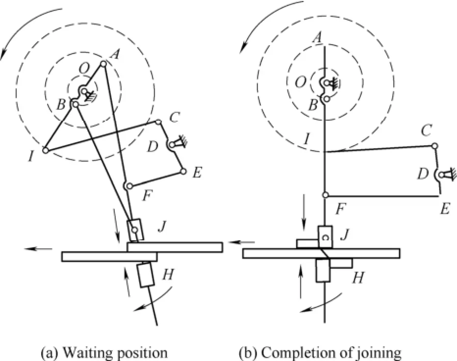
Fig. 1 Dynamic joining mechanism
Fig. 2 is the sketch of joining results of the two solid-state joining metal plates, the crop need to be removed by crop removed device.
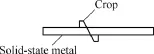
Fig. 2 Sketch of the joining result
The dynamic joining mechanism can be installed between the rough and fishing mills. Because of the joining time is short, hence, it needn't large modification of the old rolling line.
3 Kinematic Analysis
3.1 Multi-rigid-body complex vector model
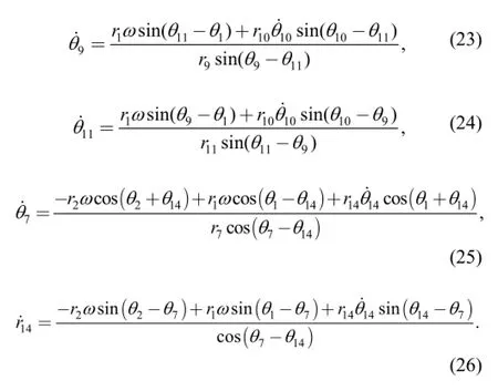
Without considering the elastic deformation of each bar,each bar is assumed as rigid body[23]. xOiy is the complex rectangular coordinates. The complex vector model of the dynamical joining mechanism is shown in Fig. 3.
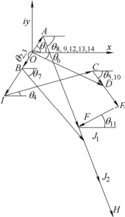
Fig. 3 Complex vector model
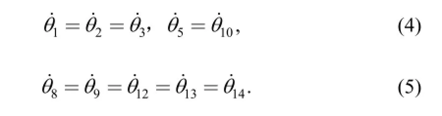
Assuming that the length of the rigid bars (OA, OB, OI,IC, CD, OD, BJ1, J1J2, AF, DE, EF, AH, FH, AJ1) are expressed as ri(i=1, 2,…, 14), respectively. The angular of each bar are presented by θi(i=1, 2,…, 14). Where J1is the hinge of the top blade, J1J2is the length of the top blade. The known quantities are θ6and the length of each bar except r14.
The relationship of the angular and speed of the each bar can be expressed by

where t is the time, ωis the angular speed of AI.
3.2 Motion equation
The complex vector method[21]is adopted to analyze the position and velocity of each part of the dynamical joining mechanism.
3.2.1 Position analysis
The closed-loop vector of OICD is shown as
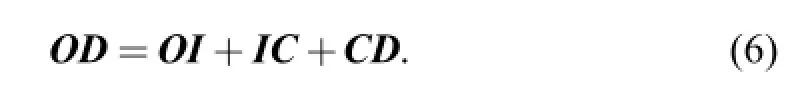
Eq. (6) can be expressed by complex vector form, one can obtain

Both sides of Eq. (7) are multiplied by conjugate complex,4θand5θ can be solved and expressed as respectively
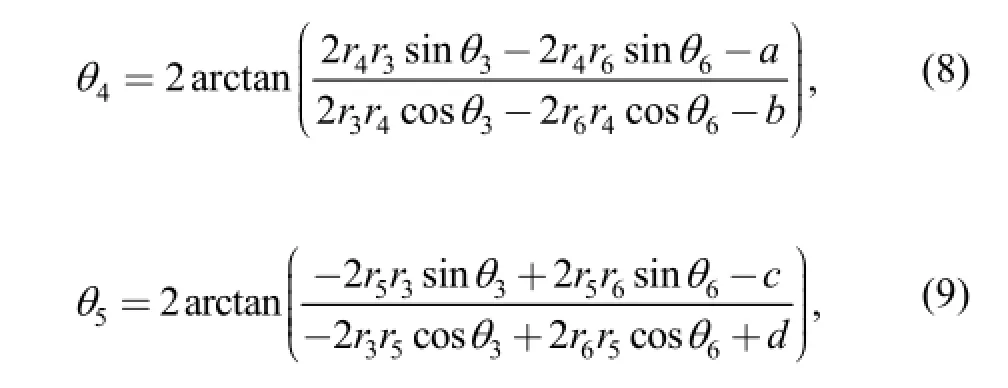
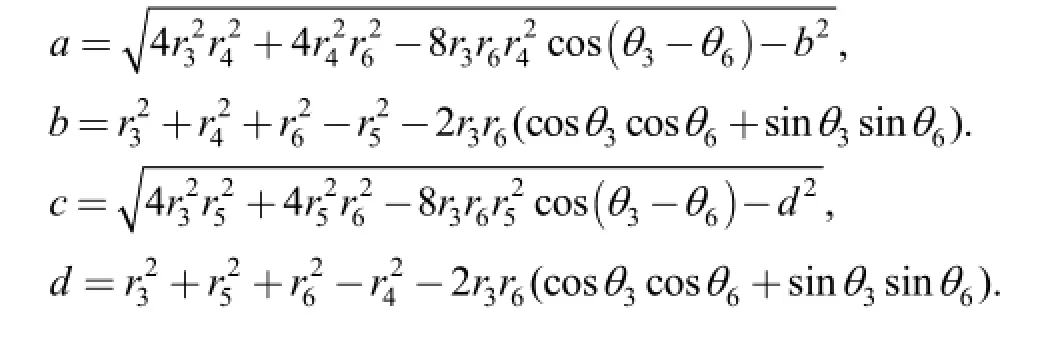
where
The closed-loop vector of OAFED is shown as
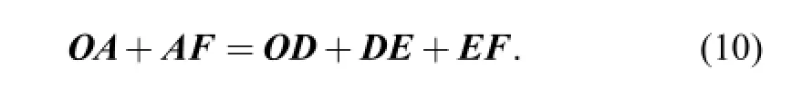
Similarly,9θand11θ can be solved, expressed as respectively
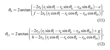
where
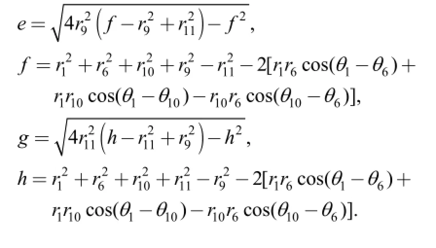
The closed-loop vector of OBJA is shown as

Similarly,7θand14r can be solved and expressed as respectively
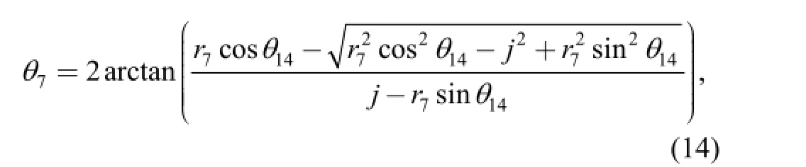
where
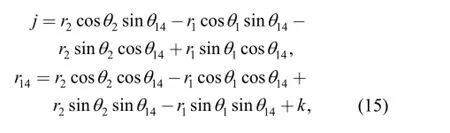
where
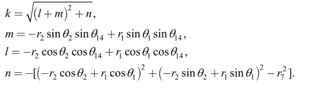
According to the geometric relation, the position of the double blades can be expressed by
where xtis the position of the top blade in x-axis, ytis the position of the top blade in y-axis, xbis the position of the bottom blade in x-axis, ybis the position of the bottom blade in y-axis.
The length L between top and bottom blade in y-axis can be expressed by

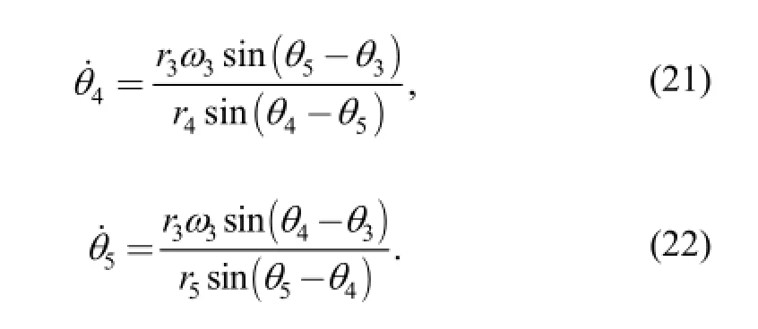
3.2.2 Speed analysis
The speed can be simply determined by differentiation ofEq. (7). Using the dot notation for the derivative, we obtain
According to the geometric relation, the speed of the double blades in x-axis can be expressed by
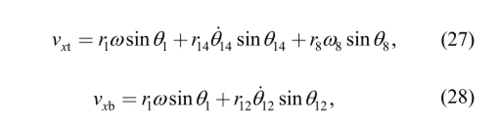
where vxtis the horizontal speed of the top blade, vxbis the horizontal speed of the bottom blade.
4 Optimization
To ensure the joining process, some principles should be followed, such as 1) To satisfy the travelling of the solid-state metal, the trajectory of the double blades should be two disjoint closed curves; 2) The blade should be vertical with the solid-state metal in the period of joining. 3)Speed of the double blades should be little larger than the speed of the solid-state metal.
When these principles can't be satisfied, the mechanism should be optimized. In this section, the objective function will be given and the constraint condition and optimization algorithm will be described.
4.1 Objective function
The double blades should realize shearing and extrusion movement and, simultaneously, the horizontal speed should approximately be equal to the speed of the metal plates. Generally, the relation of the horizontal speed should be satisfied[24]:

where vxis the horizontal speed of the blade, v is the speed of the solid-state metal plates.
Eq. (29) shows that, in the period of the shearing and extrusion, little “drawing steel” are permissible, however,serious “drawing steel” will impact the rolling process,increase the impact load. If vx<v, the blade will prevent the travelling of the solid-state metal. Hence, summation square of the difference value between the horizontal speed of the blades and the speed of the solid-state metal is selected as the objective function in the joining period,shown by
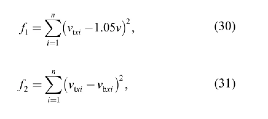
where vtxiis the discrete horizontal speed of the top blade,vbxiis the discrete horizontal speed of the bottom blade.
To ensure the joint quantity, in the joint period, the blades should be vertical to the solid-state metal, which can decrease the energy consumption and increase the service life of the mechanism. This angular can be realized by AH,hence, the angular objective function is expressed by wherei12θis the discrete angular of AH.
The parameters of the mechanism shown in Fig. 1 are transferred in matrix form, we obtain
where i=1, 2,…, 13.
A group of weighted coefficients are selected, and a new objective function is regarded by

where w1, w2and w3are the weighted coefficients, and[25]
4.2 Constraint condition
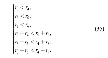
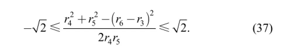
In 4-bar linkage OICD, the condition of crank OI, the shortest bar is the frame connecting rod and the summationof the longest and the shortest bar is less than the summation of the other bars[23], we obtain
The condition of transmission angle in 4-bar-linkage OICD is shown in
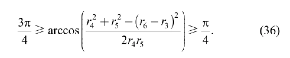
The simplification of Eq. (36) can be expressed by
The degrees of freedom of the 5-bar linkage OAFED are formulated mathematically as
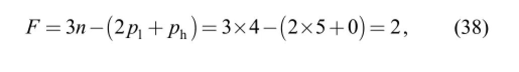
where F is the degrees of freedom, n is the numbers of the bar, plis lower pair and phis the higher pair.
Eq. (38) shows that the 5-bar linkage should be driven by two bars, it is the motion of OA and DE are known. O and D are revolute joints, AF and EF are unco-linear, which necessary and sufficient condition can be determined by[23]
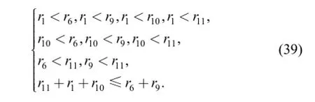
The top blade travels along AH, hence OHABJ can be regarded as slider-crank mechanism. The condition of O is the revolute joint can be expressed by
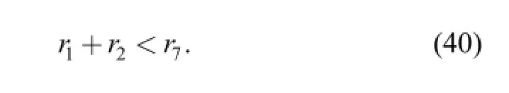
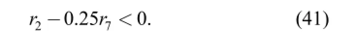
The connecting rod IJ is a important part in the mechanism, which can transform the revolute motion of OB into the upper/down motion of the top blade. The relation of OA and BJ is determined by link rod ratioλ:
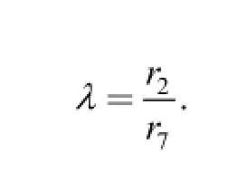
The maximumλis less than 0.25 generally[24], hence
In order to ensure the joining strength of the solid-state metal, the minimum length of the joining section can't be less than 0.8 times of one metal plate thickness. At end of the joining period, the top blade is vertical, hence
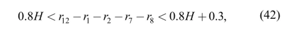
where H is the thickness of one metal plate, 0.3 is the floating value.
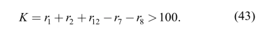
To ensure the travelling of the solid-state metal, the maximum displacement of the double blades should be larger than 100 mm, hence
Eqs. (40) and (41) show that limit position of the blades is vertical, the shearing angular should be constrained[26],shown in
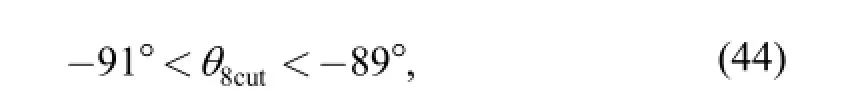
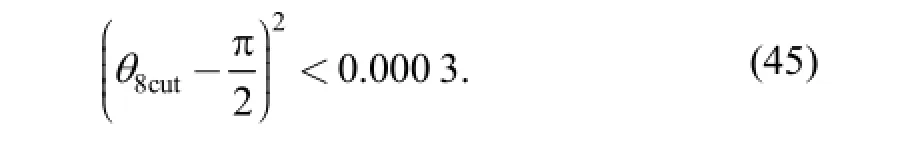
where θ8cutis the shearing angular of the top blade, Eq. (42)can be expressed by the radian form, we obtain
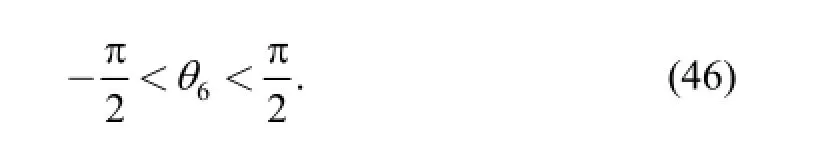
Assuming the swing angular of CDE can be expressed by
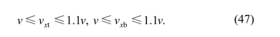
When the blades approach the solid-state metal, the speed of the blades are constrained by
4.2 Optimization based on genetic algorithm
The calculation flow of GA is shown in Fig. 4[25].
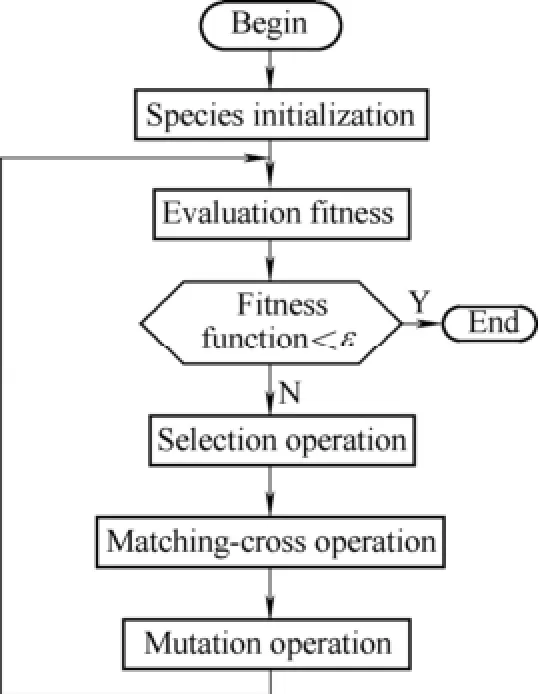
Fig. 4 Calculation flow using GA
5 Example
5.1 Initial analysis of the joining process
Based on numbers of calculation, the parameters of the dynamical joining mechanism are shown in Table 1.
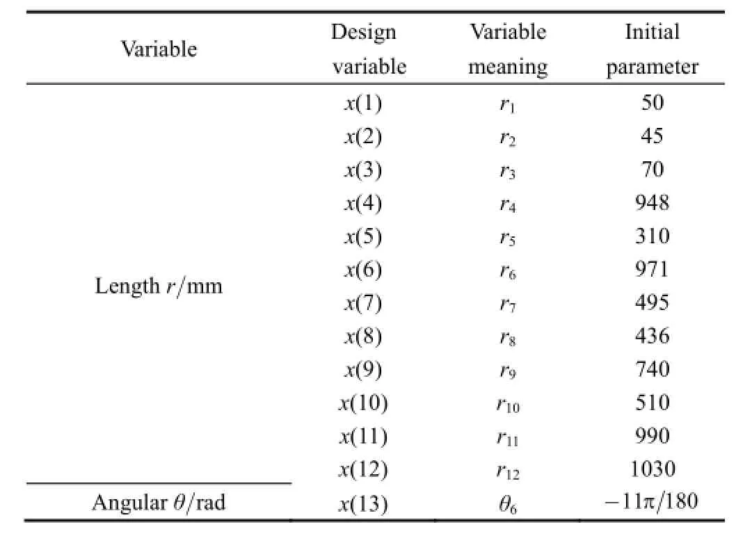
Table 1. Initial parameters of the joining mechanism
The parameters of the solid-state metal plate are listed in Table 2.
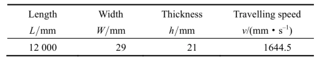
Table 2. Parameters of the solid-state metal
Based on the analysis in section 3, the trajectory of the double blades can be shown in Fig. 5.
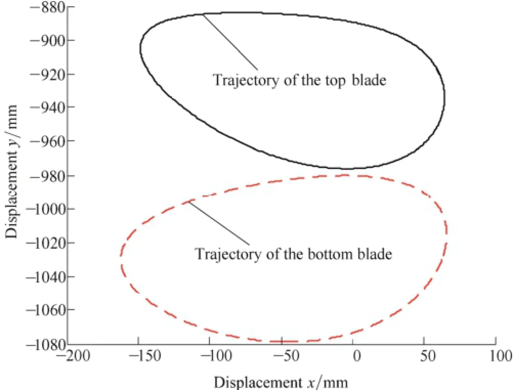
Fig. 5 Trajectory of the double blades
Fig. 5 shows that the trajectories of the double blades are closed-curves, and the two closed-curves are disjoint.
The joining relation between the blades and the solid-state metal are shown in Fig. 6.
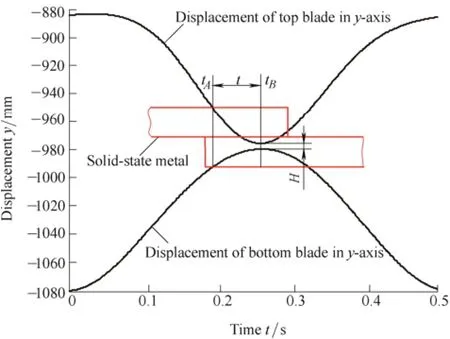
Fig. 6 Joining process
Fig. 6 are the joining process of the solid-state metal,where t is the shearing time of the blades, and H is the joining thickness of solid-state metal, are expressed respectively by
where tAis time of the blades when reaches the surface of the solid-state metal, tBis time of the blades complete the shearing, min(yt) is the minimum position of the top blade and max(yb) is the maximum position of the bottom blade. By calculation, t=0.064 s, and H=3.99 mm, the results show that the joining time is less than 0.1 s, however, the joining thickness is too thin to ensure the joining strength.
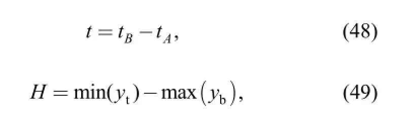
The angular of the top and bottom blades are shown in Fig. 7
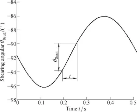
Fig. 7 Angular of the top and bottom blades
According to the analysis in section 3 and section 4, the shearing angular of the top and bottom can be solved, and shown as θ8cut=-89.75 ~ -93.77°, the results satisfy the joining process, approximately.
The horizontal speed of the blades and the speed of the solid-state metal are shown in Fig. 8.
Fig. 8 Speed of the blades and the solid-state metal
Substituting tAand tBin Eq. (27) and Eq. (28), the horizontal speed of the top blade when reaches the solid-state metal vxtA=1424 mm/s, the maximum horizontal speed of the top blade vxt=1723 mm/s, the horizontal speed of the bottom blade when reaches the lower surface of the bottom solid-state metal vxb=1467 mm/s, the horizontal maximum speed of the bottom blade vxb=1733 mm/s. The maximum hysteretic ratio between the top blade and the solid-state metal is 13.4%, the maximum preemptive ratio is 4.8%, the maximum hysteretic ratio between the bottom blade and the solid-state metal is 10.8%, and the maximum hysteretic ratio is 5.4%. The results show that the blades will prevent the travelling of the solid-state metal and it is harmful for the joining process in the early stage.
5.2 Optimization
According to the analysis in section 5.1, we can know that, this 6-bar and 1-slider mechanism can realize the shearing and extrusion moment, however, the joining thickness and the horizontal speed of the blades is harmful for the rolling process, hence, the optimization is necessary. The GA is adopted, and the parameters of the GA are shown in Table 3
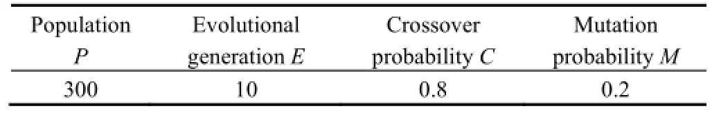
Table 3. Parameters of GA
The limited error method is used to determine the weighed coefficients[25], by calculation, w1=0.4, w2=0.4,w3=0.2, and the optimization results of the mechanism are shown in Table 4.
Substituting the values in Table 4 in Eqs. (16)-(19), the trajectory of the double blades can be shown in Fig. 9.
Substituting the values in Table 4 in Eqs. (17) and (19),the joining process are shown in Fig. 10.
By calculation, the joining time of the top blade is between 0.202-0.252 s, and the joining time of the bottom blade is between 0.202-0.268 s, and the joining thickness of the solid-state metal is 16.851 9 mm. The results show that the joining thickness of the solid-state metal is more than 80% of one metal plate, the joining thickness is ensured.
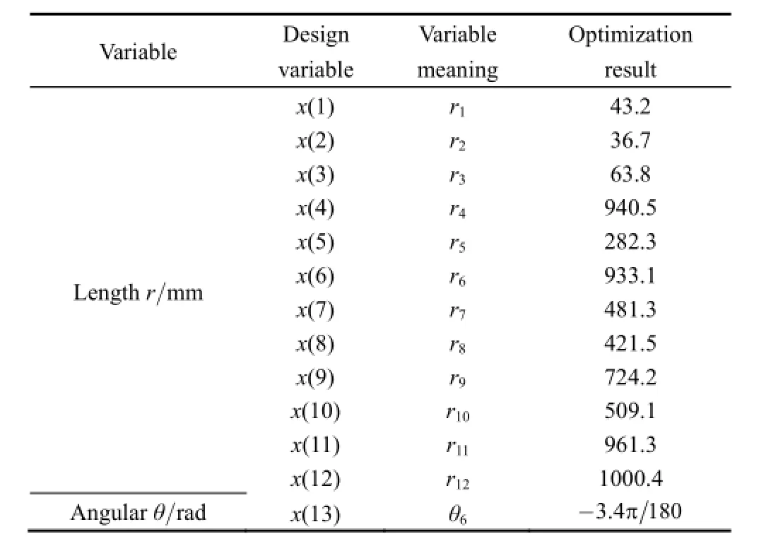
Table 4. Optimization results of the joining mechanism
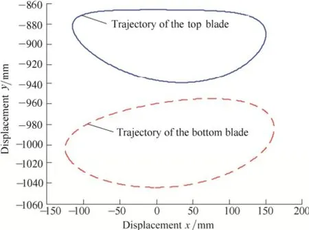
Fig. 9 Optimization trajectory of the double blades
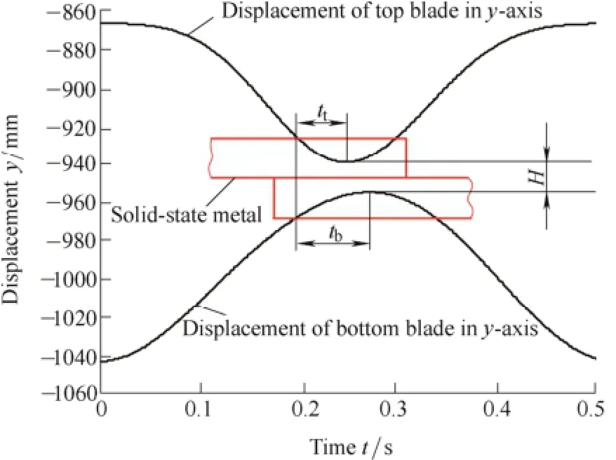
Fig. 10 Optimization joining process
The angular of the top and bottom blades are shown in Fig. 11
By calculation, the shearing angular is between -86.38~-91.02°, the results satisfy the joining process,approximately.
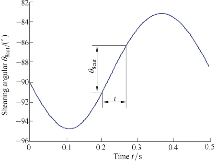
Fig. 11 Optimization Shearing angular
The horizontal speed of the blades and the speed of the solid-state metal are shown in Fig. 12.
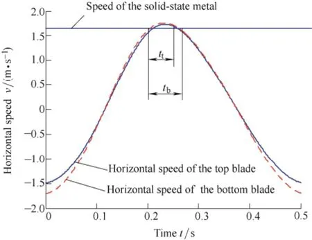
Fig. 12 Optimization speed of the blades and solid-state metal
By calculation, the horizontal speed of the blades when reach the surface of the solid-state metal is vxt=1569 mm/s,and vxb=1618 mm/s, respectively. The maximum speed of the blades vxt=1732 mm/s, and vxb=1761 mm/s,respectively. When completing the joining, the speed of the blades vxt=1686 mm/s, and vxb=1605 mm/s, respectively. The maximum hysteretic ratio of the top blade is 4.59%,the maximum preemptive ratio of the top blade is 5.32%. The maximum hysteretic ratio of the bottom blade is 1.61%,the maximum preemptive ratio of the bottom blade is 7.08%. The results show that the hysteretic and preemptive problems are improved.
6 Conclusions
(1) A relatively simple 6-bar and 1-slider mechanism used for the joining of the solid-state metal is put forward,based on the complex vector method, the kinematic functions are deduced, the joining time is less than 0.1 s.
(2) To ensure the joining thickness, the shearing angular and the horizontal speed, the optimization model is built,the objective function is given and the constraint conditions are established. The genetic algorithm are employed for the multi-objective optimization
(3) The joining thickness is larger than 0.8 of the solid-state metal, and the joining thickness is ensured, the maximum hysteretic ratio is 4.65% and the maximum preemptive ratio is 7.15%, the hysteretic and preemptive problems of the horizontal speed of the blade is improved.
[1] LIU Zhanying. Steel rolling[M]. Beijing: Metallurgical Industry Press, 1995: 53-55. (in Chinese)
[2] ZOU Jiaxiang. Rolling machinery[M]. Beijing: Metallurgical Industry Press. 2007: 14-16. (in Chinese)
[3] KANG Yonglin, ZHU Guoming. Hot strip endless rolling technology[J]. Iron and Steel, 2012, 47(2): 1-6. (in Chinese)
[4] ZHANG Zhi. Analysis and prospect on retrofit from thin slab continuous casting and rolling to endless rolling[J]. International Iron and Steel, 2012, 2: 22-26. (in Chinese)
[5] GUINDANI A, VENTURINI R, MAPELLI C, et al. Properties of hot rolled steel strips produced by endless casting-rolling plant[J]. La Metallurgia Italiana, 2014, 1: 25-30.
[6] KANG Yonglin, CAO Shuwei. Development on rolling technology of hot rolled steel at home and abroad[J]. Henan Metallurgy, 2011,19(1): 7-11. (in Chinese)
[7] YIN Ruiyu, ZHANG Hui. Progress and development direction on thin slab continuous casting and rolling technology under new situation[J]. Iron and Still, 2011, 46(4): 1-9. (in Chinese)
[8] KANG Yonglin. The technology and application progress of ultra-thin hot rolled strip produced by thin slab casting and rolling. steel rolling[J]. Steel Rolling, 2015, 32(1): 7-11. (in Chinese)
[9] YASUO I. TAKAHIRO Y, SHOJI M. Advance process control technologies for realization of endless hot strip rolling[J]. Kawasaki Steel Technical Report, 2000, 10(43): 68-74.
[10] MATSUO S. Outline of continuous finish-rolling at Oita Works[J]. Current Advance in Materials and Process, 2000, 13: 1056.
[11] WANG Limin. Development and application of endless strip production technology of ultra-thin hot-rolled strip[J]. Metallurgical Equipment, 2014, 212(1): 60-65. (in Chinese)
[12] TANG Di, ZHAO Aimin, WU Huibin, et al. New rolling technology of flat-rolling steel and product development[J]. Iron and Steel,2012, 47(11): 1-8. (in Chinese)
[13] WANG Rui, ZHANG Junwei, LIANG Tao, et al. Welding method of billet in the endless rolling technology[J]. Electric Welding Machine, 2015, 45(1): 111-114. (in Chinese)
[14] KENJI H, TOSHIHIRO U, HIDEAKI F. Development of a bar-joining apparatus for endless hot rolling[J]. Mitsubishi Heavy Industries Technical Review, 2009, 46(3): 29-35.
[15] KENJI H, TAKAO F, YASUTSUGU Y, et al. Development of super deformation joining method for hot-bar joining, a study of solid-state joining for in-line bar joining of endless hot rolling IV[J]. Journal of the JSTP, 2010, 51(588): 28-32.
[16] JONGSUB L, YOUNKEE K, CHUNSOO W, et al. Development of a new solid-state joining process for endless hot rolling[J]. Iron and Steel Technology, 2009, 6(8): 48-54.
[17] JINWOO P, CHANWOO Y, YOUNHEE K, et al. The effect of alloy compositions on the joint strength of carbon steels welded by the extended hot-rolling process[J]. Materials Science & Engineering A,2012, 558: 319-325.
[18] KANG Yonglin. Intermediate billets joining method for hot strip rolling[P], China, 201010289783.1. (in Chinese)
[19] ZHANG Shuangjie. Solid-state metal joining device by fast shearing[P], China, ZL201420026874, 2014.1.16. (in Chinese)
[20] DAI Yongjuan, ZHANG Xiaoli. Study of the solid-state joining process for endless hot rolling[J]. Applied Mechanics and Materials,2014, 633-634: 197-200.
[21] JAVOER G, DE J, EDUARDO B. Kinematic and dynamic simulation of mutibody systems[M]. Berlin: Springer-Verlag press,2000: 18-24.
[22] SUN Wenjie, LI Gang. Multiobjective optimization for the forging manipulator based on the comprehensive manipulation performance Indices[J]. Journal of Mechanical Engineering, 2014, 50(17): 52-60. (in Chinese)
[23] AN Zijun. Mechanical principle[M]. Beijing: National Defense Industry Press, 2009. (in Chinese)
[24] XIA Jianfang, YE Nanhai. The kinematics analyses of IHI swing flying shearing[J]. Journal of Central South University of Technology, 2003, 34(2): 173-176. (in Chinese)
[25] LI Wanxiang. Optimization design for engineering and the realization by MATLAB[M]. Beijing: Tsinghua University Press,2012. (in Chinese)
[26] XIA Jianfang, ZHOU Xinheng. The optimal design of IHI pendular flying shear[J]. Machine Design and Research, 2003, 19(3): 69-72.(in Chinese)
Biographical notes
ZHANG Shuangjie, born in 1966, is currently a professor at School of Materials Science and Engineering, Hebei University of Science and Technology, China. He received his PhD degree from Yanshan University, China, in 2012. His research interests include endless rolling techniques and shaping forming of the metal.
Tel: +86-311-81668685; E-mail: zsjzlili@163.com
YAO Yunfeng, born in 1979, is currently a teacher at School of Materials Science and Engineering, Hebei University of Science and Technology, China. He received his PhD degree from Yanshan University, China, in 2010. His research interests include endless rolling techniques, mold oscillation technique.
Tel: +86-311-81668705; E-mail: yaoyf@hebust.edu.cn
10.3901/CJME.2015.0729.104, available online at www.springerlink.com; www.cjmenet.com; www.cjme.com.cn
* Corresponding author. E-mail: zsjzlili@163.com
Supported by National Natural Science Foundation of China(Grant No. 51475139)
© Chinese Mechanical Engineering Society and Springer-Verlag Berlin Heidelberg 2015
February 12, 2015; revised July 21, 2015; accepted July 29, 2015
杂志排行

Chinese Journal of Mechanical Engineering的其它文章
- Influence of Alignment Errors on Contact Pressure during Straight Bevel Gear Meshing Process
- Shared and Service-oriented CNC Machining System for Intelligent Manufacturing Process
- Material Removal Model Considering Influence of Curvature Radius in Bonnet Polishing Convex Surface
- Additive Manufacturing of Ceramic Structures by Laser Engineered Net Shaping
- Springback Prediction and Optimization of Variable Stretch Force Trajectory in Three-dimensional Stretch Bending Process
- Effect of Surface Topography on Stress Concentration Factor