Motion Stability Analysis of Non-sinusoidal Oscillation of Mold Driven by Servomotor
2015-11-01YAOYunfengLIJunxiaandFANGYiming
YAO Yunfeng, LI Junxia, and FANG Yiming*
1 School of Materials Science and Engineering, Hebei University of Science and Technology,Shijiazhuang 050018, China2 Key Laboratory of Material Near-net Forming Technology of Hebei Province,Shijiazhuang 050018, China3 Key Laboratory of Industrial Computer Control Engineering of Hebei Province, Yanshan University,Qinhuangdao 066004, China 4 National Engineering Research Center for Equipment and Technology of Cold Strip Rolling,Qinhuangdao 066004, China
Motion Stability Analysis of Non-sinusoidal Oscillation of Mold Driven by Servomotor
YAO Yunfeng1,2, LI Junxia1,2, and FANG Yiming3,4,*
1 School of Materials Science and Engineering, Hebei University of Science and Technology,Shijiazhuang 050018, China
2 Key Laboratory of Material Near-net Forming Technology of Hebei Province,Shijiazhuang 050018, China
3 Key Laboratory of Industrial Computer Control Engineering of Hebei Province, Yanshan University,Qinhuangdao 066004, China 4 National Engineering Research Center for Equipment and Technology of Cold Strip Rolling,Qinhuangdao 066004, China
The investments of the electro-hydraulic servo system of the mold non-sinusoidal oscillator are great, the modification ratio of the mechanical type is unable to be adjusted online, and some continuous casters suffer from server resonance during the casting. A mold non-sinusoidal oscillation mechanism driven by servomotor is proposed and the prototype is produced in the lab, the investment is low and the modification ratio is can be adjusted online, and the stability problem is studied. At first the dynamics model of the servomotor non-sinusoidal oscillation is established, and the kinematics differential function is deduced. Furthermore, based on the harmonic balance method, the eigenvalues of the system are solved; the criterion of the stability of the system is put forward. In addition,the eigenvalues and harmonic with different oscillating parameters are analyzed. Analytical results show that the real parts of the eigenvalues are positive, the system will be unstable, and the resonance will occur when the positive real parts of the eigenvalues are extremum. A foundation is established for solving the running smooth problem and next application of this mechanism.
continuous casting, mold non-sinusoidal oscillation, servomotor, stability, resonance
1 Introduction*
Mold non-sinusoidal oscillation is one of the key techniques in development of the high-efficient continuous casting[1-3], and the mold non-sinusoidal oscillator is the pivotal mechanism[4]. Compared with sinusoidal oscillation,mold non-sinusoidal oscillation have some excellent advantages, for example, increasing casting speed,improving strand quality, reducing stick type breakout[5-6],hence, it is adopted in industry application widely.
According to the drive types, mold non-sinusoidal oscillator is divided two classes, one is electro-hydraulic servo system, and the other is mechanical system. Mold non-sinusoidal oscillator driven by electro-hydraulic servo system, which run smoothly and the waveform is adjusted flexibly[7], however, it is more disadvantageous to reform the old caster, for the great investment and operation,complex structure, and inconveniency of maintenance[8]. The mechanical type mold non-sinusoidal oscillation system was developed such as double eccentric wheel[9],ellipse gear[10], limacon gear[11]and non-circular gear[12],The investment to mechanical type is low, and can be used without the need for a large modification to the existing sinusoidal oscillator[13], unfortunately, the modification ratio, an important parameter, is unable to be adjusted online, and the oscillating stationarity is poor. A mold non-sinusoidal oscillator driven by servomotor with fuzzy PID controller is developed[14], compared with electrohydraulic non-sinusoidal oscillator, this mechanism is simpler, and the investment and maintenances is lower, and compared with mechanical non-sinusoidal oscillator, the modification ratio can be adjusted online, and the structure is more compact. FANG, et al[15-16], established the mathematical model of the mold non-sinusoidal oscillation driven by servomotor, the validity of this mechanism was verified by the experiments and theory analysis.
In recent year, with the application of the non-sinusoidal oscillation and the increasing of the oscillating frequency and casting speed, the dynamics of the mold oscillating mechanism attracts people's great attentions, because the mechanism are driven by external force, inertial force,gravitational force and frictional force of the strand, every component of the oscillator generate complex elastic vibration[17]. The finite element method was employed to analyses the nature frequency of this mechanism[18]. The lumped parameter method is adopted to study the resonance phenomenon of the ellipse gear mold oscillating mechanism[19]. FFT method was used for analysis the elastic vibration response of the mold oscillation system[20].
The paper focus on a mold non-sinusoidal oscillator driven by servomotor and its experimental prototype is produced. Furthermore, the lumped parameter model of the oscillation mechanism is built and its motion stability is analyzed using harmonic balance method and verified by harmonic analysis, which establish the basis for further study and application of this mechanism. In section 2, by controlling the angular speed of the servomotor, a experimental prototype is produced. Then in section 3, the dynamic model of mold non-sinusoidal oscillator is established. In section 4 motion stability is analyzed. In section 5, a calculation example is given, followed by discussions and conclusions.
2 Design of the Mold Non-sinusoidal Oscillator Driven by Servomotor
The mold non-sinusoidal oscillator driven by servomotor is shown in Fig. 1. It mainly consists of the four-bar-linkage guidance devices, buffer spring, oscillating table,servomotor, reducer, coupling, eccentric wheel and push rod.
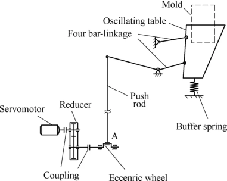
Fig. 1. Sketch of mold non-sinusoidal oscillator driven by servomotor
The servomotor rotates as variable angular speed expressed in Eq. (1)[21], passing through decelerating by the reducer, the four bar-linkage will drive the oscillating table and mold oscillates up and down.
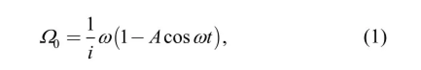
where0Ωis the angular speed of the servomotor; i is the reduce ratio; ω is the angular frequency of the eccentric wheel and A is the modification coefficient. If the amplitude of the mold ish, the displacement and velocity functions of the mold are shown by
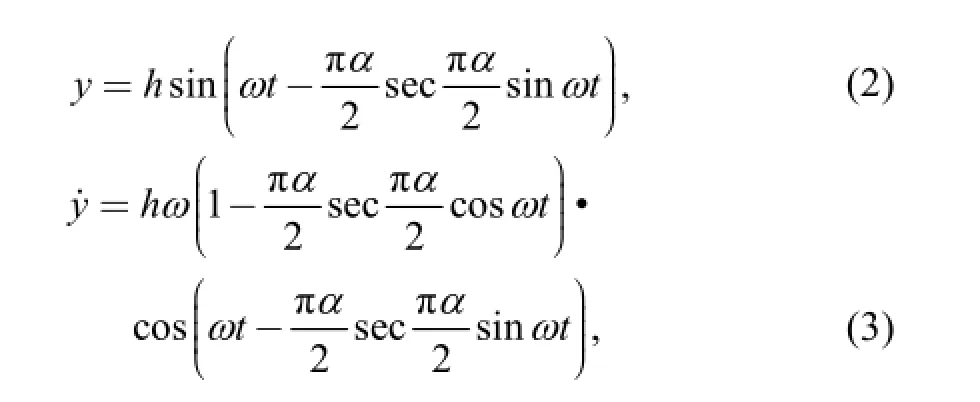
where α is the modification ratio of the non-sinusoidal waveform, and expressed by[21]

Eq. (2) and Eq. (3) are the DEMAG non-sinusoidal oscillating waveform functions[22]. If the angular speed of the servomotor is controlled by Eq. (1), the modification ratio and the frequency of the non-sinusoidal can be adjusted online. If the oscillating frequency is 120 cycles/min, the velocity curves with different modification ratio are shown in Fig. 2
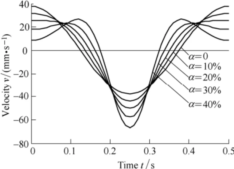
Fig. 2. Velocity waveform of mold non-sinusoidal oscillator driven by servomotor
Based on the principle, the experimental prototype is manufactured in the lab shown in Fig. 3, where the sensor is used for testing the displacement and velocity of the oscillating table, and the signals are feed back to the servomotor, and this mechanism will be adopted in one steel company.
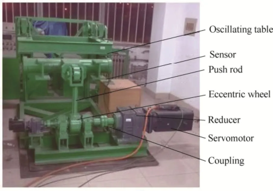
Fig. 3 Experimental prototype of mold non-sinusoidal oscillating mechanism
3 Dynamic Model of the Mold Oscillation Mechanism
3.1 Dynamic model
Compared with the transmission shaft, the stiffness of the gears is bigger, and the frequency of the mold is low,some assumptions[18-20]are as follows when the model is built.
(1) Without considering the elasticity of the reducer,only the rotational inertia of the gears is considered;
(2) The coupling is rigid and the damping is neglected;
(3) The servomotor rotates as Eq. (1), fluctuation of the rotate speed is ignored.
According to the assumptions, the dynamic model of the mold oscillation mechanism is shown as Fig. 4.
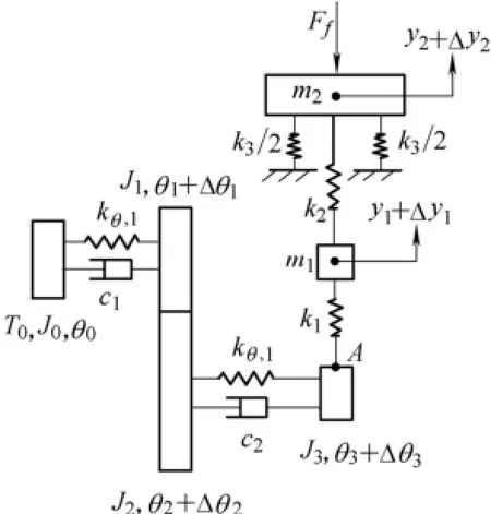
Fig. 4. Dynamic model of mold non-sinusoidal oscillation
In Fig. 4 T0is the output torque of the servomotor, θ0is the angular displacement of the servomotor,θiis the static angle displacement(i=1, 2, 3); Δθiis the elastic angle displacement(i=1, 2, 3); m1is the mass of connecting rod; m2is the mass of oscillating table and mold; J0is the moment of inertia of the motor shaft, Jiis the moment of inertia including gears, shafts and couplings(i=1, 2, 3); yiis the rigid linear displacement (i=1, 2); Δyiis the elastic linear displacement; kθ,iis the stiffness of the shaft(i=1, 2);k1is the tension and compression stiffness of upper part of the push rod; k2is the tension and compression stiffness of lower half of the push rod; k3is the stiffness of buffer spring and Ffis the friction between mold and strand.
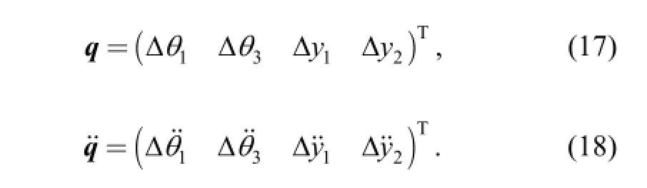
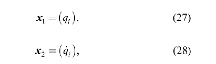
Δθ1, Δθ3, Δy1, Δy2are selected as dependent general coordinates and the other coordinates can be expressed by dependent general coordinates. The elastic deformation of the gears is not considered, so the speed ratio of the reducer is expressed by
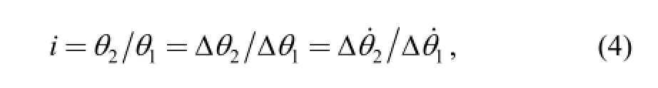
then

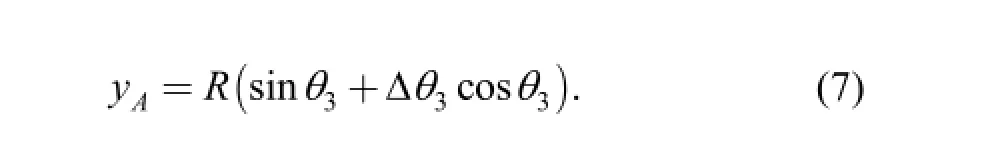
The displacement of the end of the push rod yAcan be formulated mathematically by the angle of the eccentric wheelθ3+Δθ3, expressed by

where R is the length of the eccentric wheel, then
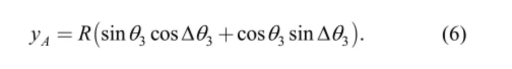
Under small deformationcos(Δθ3)≈1,sin(Δθ3)≈Δθ3,thus Eq. (6) can be resulted in
The longitudinal vibrating displacement of the rigid boys is determined by

3.2 Motion differential equation
The differential equation of motion for this model shown in Fig. 4 can be formulated by means of the well known Lagrange Equation, we can write
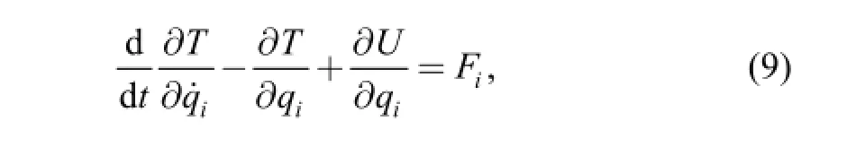
where T is the kinetic energy, U is the potential energy, Fiis the generalized force, and qiis the dependent general coordinate. T and U are shown as follows respectively:
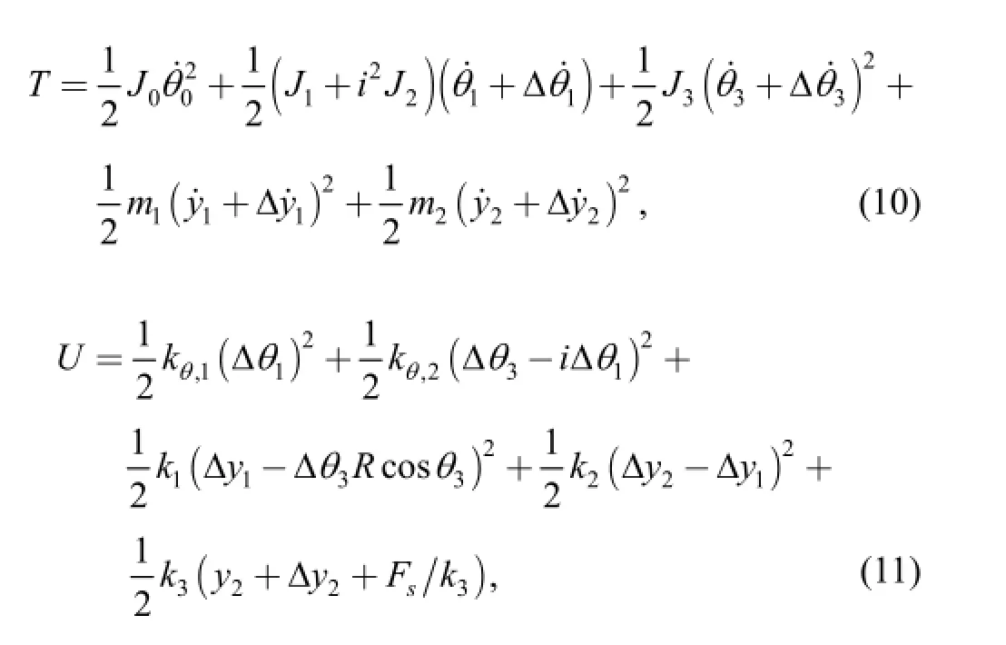
where Fsis the pre-compression force of the buffer spring,and this force is assumed to be equal to the gravity of the oscillating table and mold[23].
Substituting Eqs. (10) and (11) into Eq. (9), Eq. (9) can be expressed in matrix as follows:

where M is the mass matrix, K is the stiffness matrix, F is the generalized forces vector, q is the vector of elastic displacement, are expressed respectively by
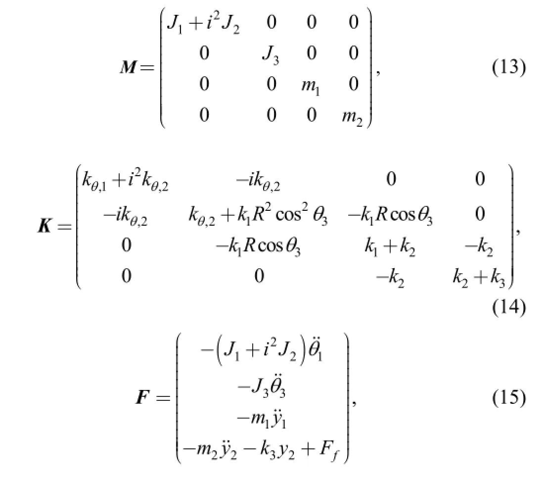
where Ffis the friction of the mold between the strands[18],expressed by
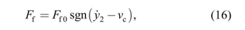
wheref0F is the amplitude of the friction.
4 Motion Stability Analysis
The complete solution of Eq. (12) consists of a periodic solution and a transient solution. In this section,approximate methods for finding the periodic and transient solution and a method for determining their stability will be discussed.
4.1 Periodic solution
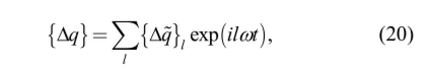
According to the characteristic of the motion differential equation, its periodic solution can be approximately solved by harmonic balance method[24]. The followings are transformed from of Eq. (12):

whereQ=M-1K,S=M-1F, and whenthe periodic solution of (19) can be expressed by
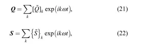
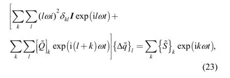
where I is the four-order identity matrix, and
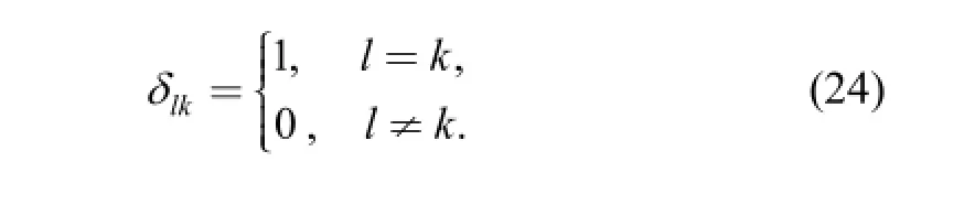
In Eq. (23), every individual harmonic is balanced, one can obtain
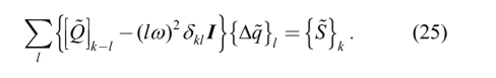
From this harmonic balance method, the coefficients{Δq} can be solved, the accuracy of which depends on the intercept order of l and k.
4.2 Transient solution
The transient solution can be regard as the disturbance,which can be obtained by the homogeneous equation of Eq.(19), that is
When the transient solution is convergent, the system is stable, when the transient solution is divergent, the system is unstable and when the transient solution is equal to zero,the system is critical stable.
Let
and in space state form, Eq. (19) can be expressed by
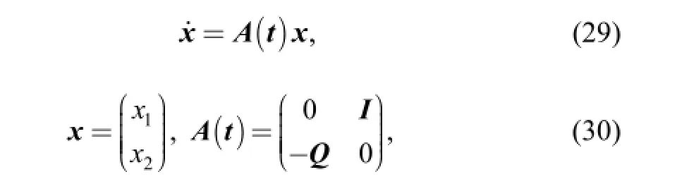

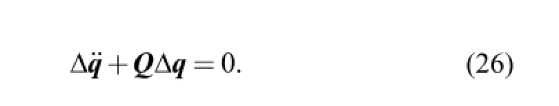
where T is the period of the mold, expressed by
Based on Floquet theory[25], the solution of Eq. (26) can be expressed by
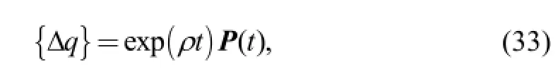
whereρis the eigenvalue of A(0), the stability depends on the real part of ρ, and the imaginary part of ρ is the vibrating frequency of the transient solution[26]. P(t) is periodic matrix, and P(t) is expanded as the Fourier series,these equations are as follows:
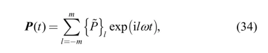
where m is the intercept order of the harmonic,is the l order displacement of the harmonics.
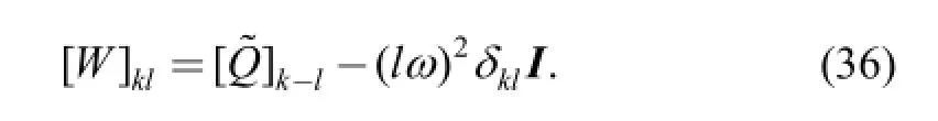
Substituting Eqs. (21), (33), (34) into Eq. (26), we have
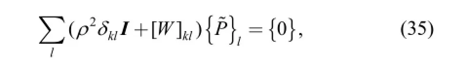
where k=(-m, -m+1,…, m-1, m), and
Let
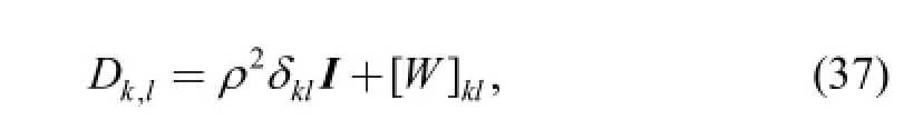
Eq. (35) can be expressed by
Let the determinant of Eq. (38) equal zero, the eigenvalues ρcan be solved, that is
From Eq. (33), if the real parts of the eigenvalues Re(ρ)>0, the displacements of the free vibrations will increase with time, and the mold oscillating system will be unstable, which can lead to the serious elastic vibration of the mold oscillation system, and the process of the casting can't be ensured. When the real parts of the eigenvalues Re(ρ)<0, the displacements of the free vibration will decrease with time, and the mold oscillation system will be stable, the stationary of the mold can be satisfied. When the real parts of the eigenvalues Re(ρ)=0, the system will be critical stability, the elastic vibration depends on the periodic solution.
5 Example
From the analysis above, we can know that the stability of the mold oscillation system depends on the oscillating parameters and the system parameters. The prototype parameters of the non-sinusoidal oscillation system are listed in Table 1.
5.1 Effect of oscillating parameters on the stability
In order to obtain good process parameters, the oscillating parameters need to be adjusted in continuous casting process. When the DEMAG non-sinusoidal function is adopted, the angle of the eccentric wheel can be expressed by
The synchronous control model of frequency with speed(m/min) adopted is expressed in Eq. (41) during calculation:
5.1.1 Effect of the amplitude
When the modification ratio α=30%, according to the analysis in section 4. The real parts of the eigenvalues with different amplitude are obtained, shown in Fig. 5, Fig. 6 and Fig. 7, respectively.
Fig. 5-Fig. 7 show that, the real parts of the eigenvlues change with frequency, and when the amplitude increases,the maximum value of Re(ρ) also increases. When themold oscillates in the positive interval, the mold will be unstable, especially the positive peak value.
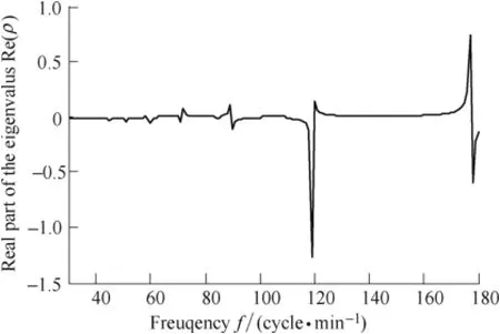
Fig. 5 Real parts of the eigenvalues when h=3 mm
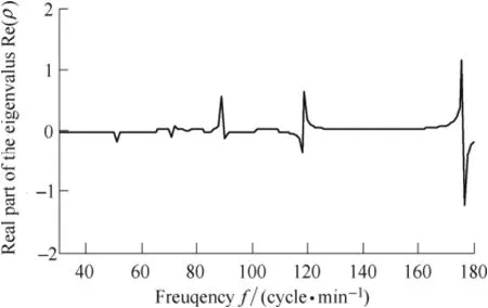
Fig. 6 Real parts of the eigenvalus when h=5 mm
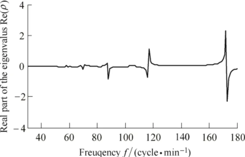
Fig. 7 Real parts of the eigenvalues when h=10 mm
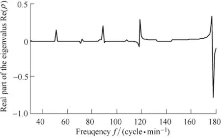
Fig. 8 Real parts of the eigenvalues when %20=α
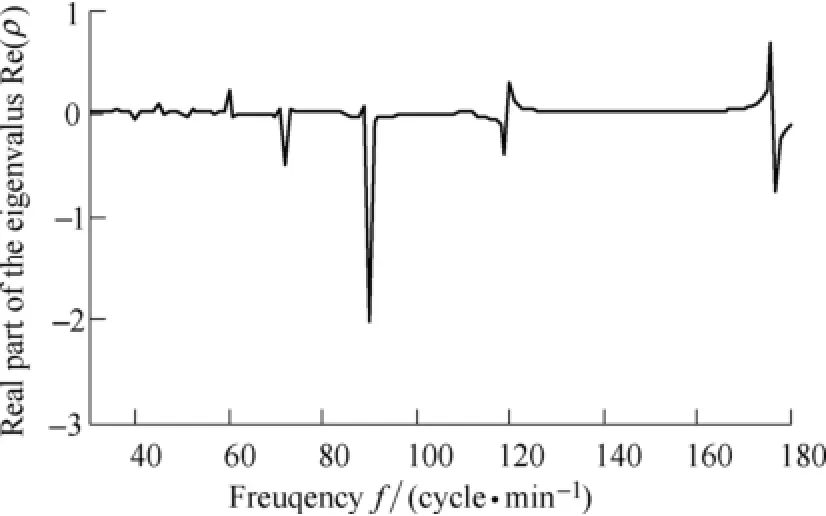
Fig. 9 Real parst of the eigenvalues when %40=α
5.1.2 Effect of the modification ratio
Modification ratio is a important parameter of non-sinusoidal oscillating. When the amplitude h=3 mm,the real parts of the eigenvalues ()Reρ with different modification ratio are shown in Fig. 5, Fig. 8 and Fig. 9,respectively.
Fig. 5, Fig. 8 and Fig. 9 show that, when the modification ratio increases, the maximum value of ()ρRe also increase.
5.2 Resonance analysis
Fig. 5-Fig. 9 show that when the frequency and modification ratio are adjusted online, the real parts of eigenvalues have positive extremum, the motion of the mold is unstable, and the mold is possible to be resulted in resonance. To verify the motion stability analysis, harmonic balance method is adopted, and the elastic displacements of mold2yΔ are obtained. When the amplitude h=3 mm, modification ratio30%α=, the 1st-4th harmonic are shown in Fig. 10.
When the amplitude h=10 mm, modification ratio α=30%, the 1st-4th harmonic are shown in Fig. 11.
Fig. 10 show that, when the mold oscillates in the frequency of f=30-180 cycle/min, the 1st-4th harmonic resonance occurs when f=120, 177 cycle/min, respectively. Comparing with Fig. 4, we can find that when the resonance occurs, the real parts of the eigenvalues Re(ρ)are the peak values; the resonance should be ignored when the oscillation frequency is 72, 89 cycle/min, because the harmonic value is small.
Fig. 11 show that, when the mold oscillates in the frequency of f=30-180 cycles/min, 1st-4th harmonic resonance occurs when f=117, 172 cycle/min, respectively. Comparing with Fig. 6, we can find that when the resonance occurs, the real parts of the eigenvalues Re(ρ)are the peak value; the resonance should be ignored when the oscillation frequency is 71, 87 cycle/min, because the harmonic value are small.
6 Conclusions
(1) A mold oscillation system driven by servomotor is developed, and the experimental prototype is produced in the lab. By controlling the angular speed of the servomotor, the modification ratio and the frequency of the non-sinusoidal function can be adjusted online.
(2) The dynamic model of the servomotor non-sinusoidal oscillation system of mold is built, the motion differential equation show that the mold oscillation system is a periodic time-varying parameters system.
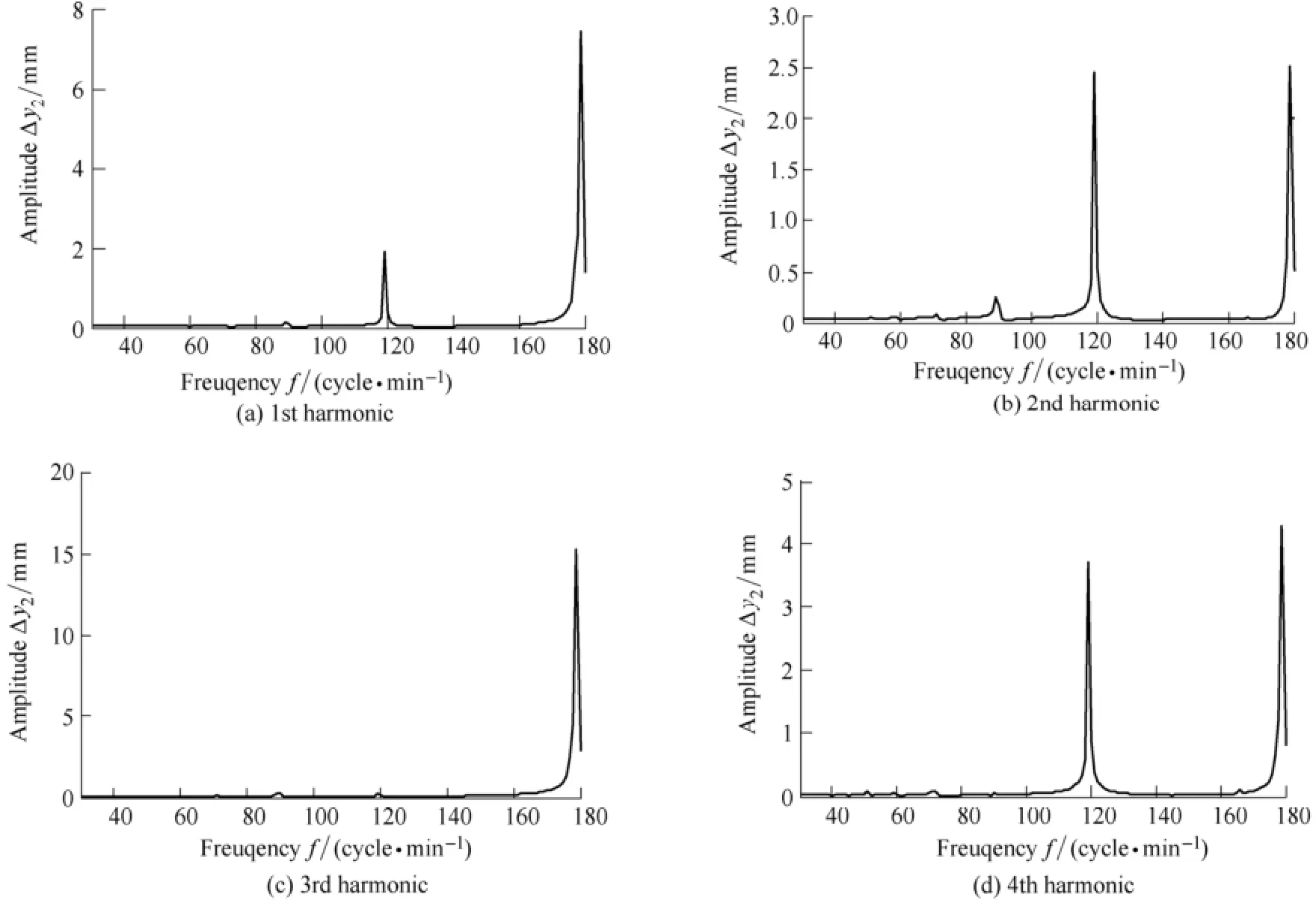
Fig. 10 Amplitude of the 1st-4th harmonic of2yΔ
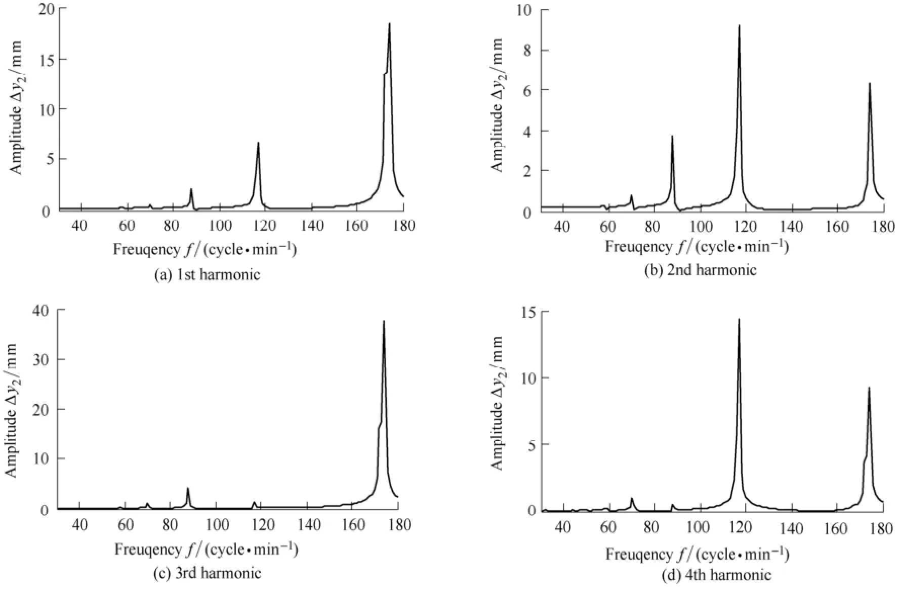
Fig. 11 Amplitude of the 1st-4th harmonic of2yΔ
(3) Mold should oscillate out of the positive range of the real parts of the eigenvalues, and the resonance will occur especially when the mold oscillates at the positive peak value of the real parts of the eigenvalues.
[1] ZHANG Xingzhong, ZHENG Xueran, LIU Qingguo, et al. Investigation and application of non-sinusoidal oscillation technique of mold[J]. Journal of Iron and Steel Research International, 2013,20(12): 19-24.
[2] YIN Ruiyu. Development of continuous casting in China in the 21st century[J]. Journal of Iron and Steel Research International, 2008,15: 1-12.
[3] REN Tingzhi, LIU Cai. Theoretical study of an oscillating waveform function and parameters for controlling the non-sinusoidal oscillation of a mold[J]. Chinese Journal of Mechanical Engineering, 2004, 17(4): 606-608.
[4] ZHANG Liping, LI Xiankui, YAO Yunfeng, et al. Study on cascaded whole-leaf spring oscillation mechanism for mould in continuous casting[J]. Ironmaking and Steelmaking, 2010, 37(3): 201-210.
[5] WANG Xudong, YAO Man, ZHANG Li, et al. Optimization of oscillation model for slab continuous casting mould based on mould friction measurements in plant trial[J]. Journal of Iron and Steel Research International, 2013, 20(1): 13-20.
[6] ZHANG Xingzhong, LIU Qingguo, HUANG Wen, et al. Investigation of non-sinusoidal oscillation waveform function and technological parameters for continuous casting mold[J]. Iron and Steel, 2014, 49(8): 41-47. (in Chinese)
[7] MIKIO Suzuki, HIDEAKI Mizukami, TORU Kitagawa, et al. Development of a new mold oscillation mode for high-speed casting of steel slabs[J]. ISIJ International, 1991, 31(3): 254-261.
[8] LI Xiankui, ZHANG Deming. Oscillation technique of mold for continuous casting[M]. Beijing: Metallurgical Industry Press, 2000: 55-60. (in Chinese)
[9] LI Xiankui, ZHENG Xueran, YU Minzhi, et al. Exploitation of non-sinusoidal oscillation of mechanically driven mold[J]. Iron and Steel, 2000, 35(12): 26-29. (in Chinese)
[10] ZHANG Xingzhong, LI Xiankui, ZHENG Xueran, el al. Study of non-sinusoidal oscillation of mold driven by ellipse gears[J]. Chinese Journal of Mechanical Engineering, 2004, 40(11): 178-182. (in Chinese)
[11] REN Tingzhi, CHENG Aiming, JING Fengru. Limacon gear and conjugated gear's geometry analyse and simulation[J]. Chinese Journal of Mechanical Engineering, 2006, 42(9): 71-75. (in Chinese)[12] LIU H P, QIU S T, GAN Y, et al. Development of mechanical drive type nonsinusoidal oscillator for continuous casting of steel[J]. Ironmaking and Steelmaking, 2002, 29(3): 180-184.
[13] LIU Dawei, REN Tingzhi. Research on nonsinusoidal oscillation of mold driven by noncircular gear[J]. Chinese Mechanical Enginerring, 2013, 24(3): 327-331. (in Chinese)
[14] YAO Yunfeng, LI Xiankui, ZHANG Xingzhong, et al. Fuzzy PID control of mold non-sinusoidal oscillator driven by permanent magnet synchronous motor[J]. Int. J. Modelling, Identification and Control, 2010, 11(3/4): 194-202.
[15] FANG Yiming, YU Xiao, NIU Ben, et al. Speed control with adaptive fuzzy terminal sliding mode for permanent magnet synchronous motor[J]. Journal of Central South University (Science and Technology), 2013, 44(12): 4855-4860. (in Chinese)
[16] FANG Yiming, LI Gongyin, LI Jianxiong, et al. Modeling and analysing for oscillation system of continuous casting mold driven by servo motor[J]. Chinese Journal of Scientific Instrument, 2014,35(11): 2615-2623. (in Chinese)
[17] LIU Hongzhao, WANG Jianping, YUAN Daning, el al. Dynamic characteristics analysis and resonances research on mold oscillator mechanism for continuous casting[J]. Chinese Journal of Mechanical Engineering, 2002, 38(3): 79-82. (in Chinese)
[18] YANG Hongpu, LI Xiankui, ZHANG Xingzhong, et al. Harmonic resonance on non-sinusoidal oscillation of mold[J]. Chinese Journal of Mechanical Engineering, 2007, 43(7): 207-212. (in Chinese)
[19] LI Xiankui, YANG Hongpu, YANG Ladao. Low-frequency resonance of mold driven by oval gears[J]. Chinese Journal of Mechanical Engineering, 2008, 44(5): 231-237. (in Chinese)
[20] ZHANG Liping, WANG Jianxiao, LU Qinghua, et al. Research on the elastic vibration response of new non-sinusoidal oscillation system for the mold[J]. Chinese Journal of Mechanical Engineering, 2011, 47(19): 91-96. (in Chinese)
[21] YAO Yunfeng, LI Xiankui, LI Junxia, et al. Mold non-sinusoidal oscillation driven by permanent magnet synchronous motor[J]. Journal of Machine Design, 2010, 27(7): 33-36. (in Chinese)
[22] BÖCHER G, GÖHLER U, HOFFMANN U, el al. Operational experience with a resonance mould for continuous casting of slabs[C]//Proceeding of 2nd European Continuous Casting Conference, Düsseldorf. 1994: 141-147.
[23] YAO Yunfeng, LI Xiankui, FANG Yiming, et al. Study of non-sinusoidal oscillation of continuous casting mold driven by servomotor[J]. Journal of Iron and Steel Research International,2008, 15(Supp.): 558-562.
[24] SCHWAB A L, MEIJAARD J P. Small vibrations superimposed on a prescribed rigid body motion[J]. Multibody System Dynamics,2002, 8: 29-49.
[25] GAO Weibing. Foundation of motion stability[M]. Beijing: Higher Education Press, 1987: 247-256. (in Chinese)
[26] KONG Xiangdong, WANG Yiqun. Basic of the control engineering[M]. Beijing: China Machine Press, 2008: 60-62. (in Chinese)
Biographical notes
YAO Yunfeng, born in 1979, is currently a teacher at School of Materials Science and Engineering, Hebei University of Science and Technology, China. He received his PhD degree from Yanshan University, China, in 2010. His research interests include high-efficient continuous casting techniques, mold oscillation technique.
Tel: +86-311-81668705; E-mail: yaoyf@hebust.edu.cn
LI Junxia, born in 1982, is currently a teacher at School of Materials Science and Engineering, Hebei University of Science and Technology, China. She received his master degree in Yanshan University, China, in 2009. Her research interests include high-efficient continuous casting techniques, mold oscillation technique.
E-mail: lijx@hebust.edu.cn
FANG Yiming, born in 1965, is currently a professor at Yanshan University, China. He received his PhD degree from Yanshan Universtiy, China, in 2003. His main research directions include automation technology and application of continuous casting and steel rolling, modeling and controlling of complex system,adaptive robust control theory and application.
Tel: +86-335-8057041; E-mail: fyming@ysu.edu.cn
10.3901/CJME.2015.0714.093, available online at www.springerlink.com; www.cjmenet.com; www.cjme.com.cn
* Corresponding author. E-mail: fyming@ysu.edu.cn
Supported by National Natural Science Foundation of China and Baosteel Group Co. Ltd.(Grant No. U1260203), Natural Science Foundation Steel and Iron Foundation of Hebei Province, China(Grant No. F2013203291), Doctor Startup Foundation of Hebei University of Science and Technology, China(Grant No. QD201247), and Foundation of Hebei University of Science and Technology, China(Grant No. XL201004)
© Chinese Mechanical Engineering Society and Springer-Verlag Berlin Heidelberg 2015
November 30, 2014; revised July 6, 2015; accepted July 14, 2015
杂志排行

Chinese Journal of Mechanical Engineering的其它文章
- Influence of Alignment Errors on Contact Pressure during Straight Bevel Gear Meshing Process
- Shared and Service-oriented CNC Machining System for Intelligent Manufacturing Process
- Material Removal Model Considering Influence of Curvature Radius in Bonnet Polishing Convex Surface
- Additive Manufacturing of Ceramic Structures by Laser Engineered Net Shaping
- Kinematics Analysis and Optimization of the Fast Shearing-extrusion Joining Mechanism for Solid-state Metal
- Springback Prediction and Optimization of Variable Stretch Force Trajectory in Three-dimensional Stretch Bending Process