Fluid-structure Interaction Analysis and Lifetime Estimation of a Natural Gas Pipeline Centrifugal Compressor under Near-choke and Near-surge Conditions
2015-11-01JUYapingLIUHuiYAOZiyunXINGPengandZHANGChuhua
JU Yaping*, LIU Hui, YAO Ziyun, XING Peng and ZHANG Chuhua
1 School of Energy and Power Engineering, Xi'an Jiaotong University, Xi'an 710049, China2 Shanghai Marine Equipment Research Institute, Shanghai 200031, China3 Petro China Beijing Gas Pipeline Ltd., Beijing 100080, China
Fluid-structure Interaction Analysis and Lifetime Estimation of a Natural Gas Pipeline Centrifugal Compressor under Near-choke and Near-surge Conditions
JU Yaping1,*, LIU Hui2, YAO Ziyun3, XING Peng1, and ZHANG Chuhua1
1 School of Energy and Power Engineering, Xi'an Jiaotong University, Xi'an 710049, China
2 Shanghai Marine Equipment Research Institute, Shanghai 200031, China
3 Petro China Beijing Gas Pipeline Ltd., Beijing 100080, China
Up to present, there have been no studies concerning the application of fluid-structure interaction (FSI) analysis to the lifetime estimation of multi-stage centrifugal compressors under dangerous unsteady aerodynamic excitations. In this paper,computational fluid dynamics (CFD) simulations of a three-stage natural gas pipeline centrifugal compressor are performed under near-choke and near-surge conditions, and the unsteady aerodynamic pressure acting on impeller blades are obtained. Then computational structural dynamics (CSD) analysis is conducted through a one-way coupling FSI model to predict alternating stresses in impeller blades. Finally, the compressor lifetime is estimated using the nominal stress approach. The FSI results show that the impellers of latter stages suffer larger fluctuation stresses but smaller mean stresses than those at preceding stages under near-choke and near-surge conditions. The most dangerous position in the compressor is found to be located near the leading edge of the last-stage impeller blade. Compressor lifetime estimation shows that the investigated compressor can run up to 102.7 h under the near-choke condition and 200.2 h under the near-surge condition. This study is expected to provide a scientific guidance for the operation safety of natural gas pipeline centrifugal compressors.
three-stage pipeline centrifugal compressor, natural gas, aerodynamic performance, structural durability, lifetime estimation,choke, surge
1 Introduction*
Pipeline centrifugal compressors are critically important for natural gas transmission systems in that they can boost pressure and thus drive natural gas throughout pipelines over long distances. Compared with compressors in other application areas, natural gas pipeline centrifugal compressors constantly operate at off-design points due to variations of upstream supply sources and downstream market demands. Besides, these compressors are expected to operate ceaselessly to guarantee continuous gas supply[1]. Therefore, the performance and durability of these compressors are equally vital to their economical and safe operation.
As the key rotating components of multi-stage centrifugal compressors, the impellers are mainly subjected to two types of loads, i.e., centrifugal force and unsteady aerodynamic force. The former is responsible for the static stress in the impeller while the latter mainly contributes to the alternating stress, a major factor affecting the forced response of the impeller. This unsteady aerodynamic excitation can be extremely dangerous at/around surge and choke points. At/around surge and choke points, the internal flow field of the compressor becomes seriously deteriorated with intensified flow disorder as well as increased fluctuation pressure acting on impeller blades,leading to larger blade deformations and even fatigue failure such as fracture[2-5]. Therefore, with respect to the natural gas pipeline centrifugal compressor that frequently operates far from the design point, it is of great necessity to assess the impact of unsteady aerodynamic force on the structural durability of the impeller. This can help understand the main mechanisms behind compressor operational failure and put forward countermeasures.
Forced response of the centrifugal impeller due to unsteady aerodynamic force is regarded as a fluid-structure interaction (FSI) problem, which can be solved via the multidisciplinary approach that combines computational fluid dynamics (CFD) and computational structural dynamics (CSD). According to the modes by which CFD is integrated with CSD, numerical approaches to FSI problems can be grouped into two categories, i.e., the strong coupling approach and the weak coupling approach[6-9]. The strong coupling approach treats the fluid and structure dynamics in a reformed and unified mathematical framework under implicit interfacial conditions. Although this approach can achieve a straight forward solution for all the unknowns of the coupled system, its application is severely limited due to mathematical and/or numerical difficulties in developing such a specialized solver. The weak coupling approach, on the other hand, treats fluid and structure as separate computational fields under explicit interfacial conditions,which thus enables a good use of the available CFD and CSD solvers. In the weak coupling approach, the information communication between fluid and structure solutions can be either one-way or two-way. The major difference between them is that the fluid mesh in the one-way FSI model remains unaffected by structural displacement while the fluid mesh in the two-way FSI model is constantly affected by structural displacement and is updated within each time step.
Over the past years, extensive numerical studies have been published regarding the FSI analysis of turbo machinery. However, most of these studies were focused on turbine engines, pumps or axial compressors rather than centrifugal compressors[3,8-16]. DICKMANN, et al[3],adopted a one-way FSI model to investigate the blade vibration behavior excited by unsteady aerodynamic force in a single-stage centrifugal compressor under near-surge and near-choke conditions and the predicted blade displacements were found to agree well with their experimental data. LERCHE, et al[14], presented another one-way FSI model to predict the dynamic stresses in centrifugal impeller blades and validated the efficiency of their model using experimental data obtained from strain gauges mounted on rotating compressor blades. Later, they adopted the same method to investigate the influence of wake disturbance from upstream vanes on the dynamic stresses in the blades of a liquefied natural gas centrifugal compressor[15]. Other major contributions to FSI analysis of centrifugal compressors are made by MAO, et al[16]and more recently by XIE, et al[4].
All the above studies have confirmed that the one-way FSI model is sufficient for the prediction of the forced response of impeller blades in centrifugal compressors. However, few of these studies intended to apply the FSI analysis results to the lifetime estimation of compressors. Only MAO, et al[16], attempted to estimate the lifetime of a single-stage centrifugal compressor. It still remains unknown how long a multi-stage centrifugal compressor would survive under dangerous unsteady aerodynamic excitations. Therefore, in this study, particular efforts are devoted to the application of FSI analysis results to the lifetime estimation of a three-stage natural gas centrifugal compressor, by which the impact of unsteady aerodynamic force on impeller structure durability can be predicted.
The compressor investigated is a three-stage natural gas pipeline centrifugal compressor which is currently running in a natural gas transmission station in North China. The purposes of this research are as follows: (1) To conduct FSI analysis for the prediction of alternating stresses in rotating impeller blades under near-choke and near-surge conditions;(2) To estimate the impeller lifetime for the assessment of the compressor survivability under such operating conditions. The results of the study are expected to provide useful guidelines for operational safety of the natural gas pipeline centrifugal compressor.
2 Compressor Description
The geometry of the investigated natural gas pipeline centrifugal compressor is shown in Fig. 1. The compressor is composed of three-stage impellers and each impeller contains 18 three-dimensional backswept blades with ruled surfaces. The exit diameters of the first-, second-, and third-stage impellers are 480 mm, 470 mm and 475 mm,respectively. The turn channel of the first- or second-stage impeller is equipped with 16 two-dimensional guide vanes. The design rotational speed of the compressor is 8600 r/min. Besides, all impellers are made of FV520B stainless steel,whose material properties are listed in Table 1.
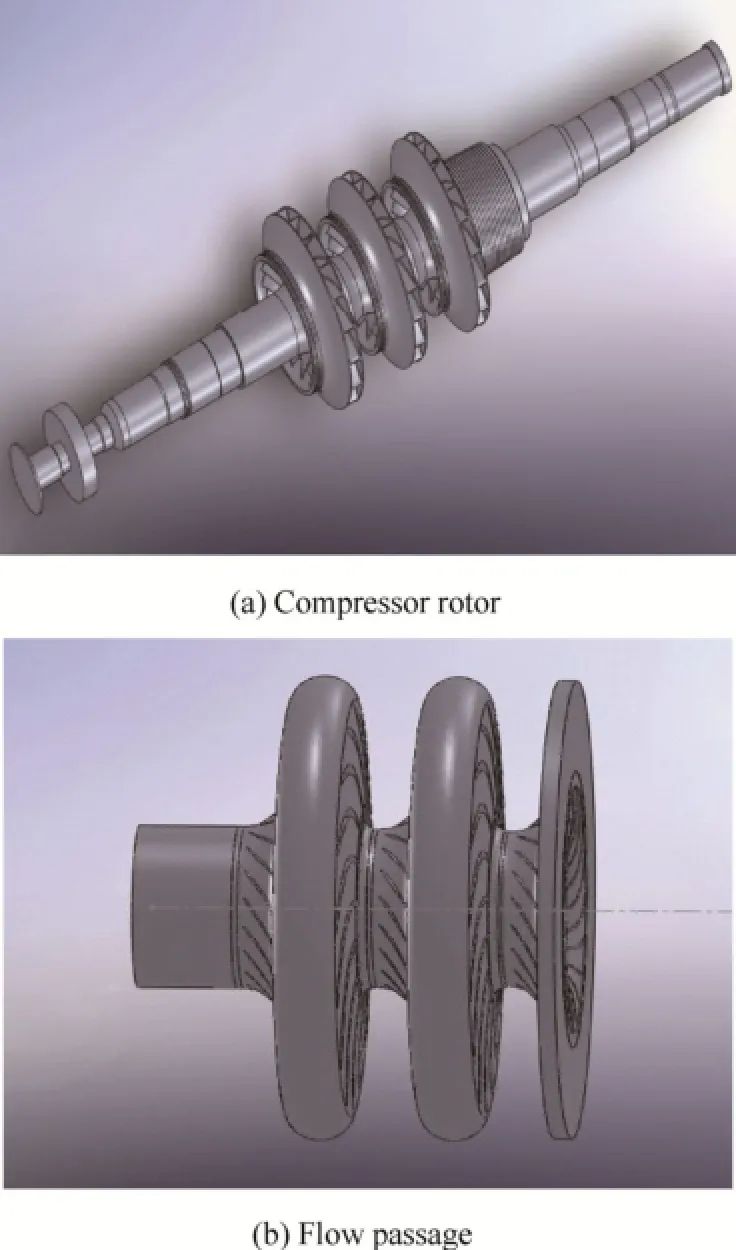
Fig. 1. 3D geometric modelof the natrual gas pipeline centrifugal compressor
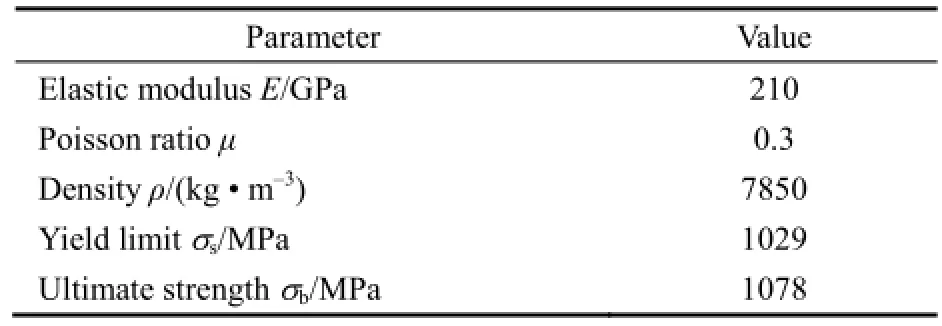
Table 1. Material properties of FV520B stainless steel
The natural gas flowing through the compressor is a mixture of hydrocarbon compounds, including most methane and small amounts of ethane, propane, butane and pentane. Its thermophysical properties are calculated using the average process exponent model and are listed in Table 2.
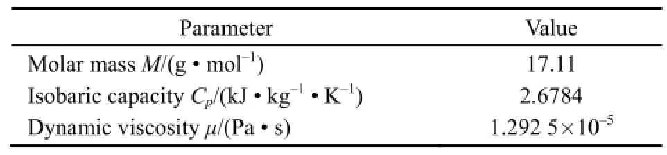
Table 2. Thermophysical properties of natural gas
3 Methodology
3.1 Overview
The flowchart of the present methodology is illustrated in Fig. 2. In the first step, the aerodynamic performance map of the three-stage natural gas centrifugal compressor is obtained by steady CFD simulations. Second, unsteady CFD simulations are performed to analyze the time varying aerodynamic pressure acting on impeller blades under near-choke and near-surge conditions. Third, the CSD method is adopted through a one-way coupling FSI model to predict alternating stresses in impeller blades induced by unsteady aerodynamic force and centrifugal force. In this step, the unsteady aerodynamic pressure is passed to the CSD solver while the structural deformations are not passed back to the fluid domain. Hence, the influence of blade deformations on the flow field is neglected.
Once the alternating stresses in blades are obtained from the above FSI analysis, dangerous positions can be determined, which are acknowledged as the primary contributor to the operational failure of the compressor. Finally, the widely used nominal stress approach is adopted to estimate the compressor lifetime. As shown in Fig. 2,three prerequisites are required for lifetime estimation, i.e.,the equivalent stress spectrum, the S-N curve of the impeller material and the Miner Rule. The detailed implementation of the nominal stress approach is presented below.
3.2 CFD solver
The aerodynamic performance of the natural gas centrifugal compressor is obtained using the commercial CFD software ANSYS CFX 13.0. The three-dimensional Reynolds-averaged Navier-Stokes equations are solved by element-based finite volume method. The second-order backward Euler scheme is adopted to discretize the time terms. The convection terms are discretized by a high resolution scheme, and the diffusion and pressure gradient terms by the shape functions in the standard finite-element approach. The k-ε turbulence model with scalable wall functions is applied to close the governing equations since its accuracy and robustness have been demonstrated in unsteady CFD simulations of centrifugal compressors in Ref. [17].
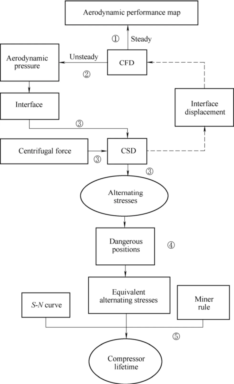
Fig. 2. Flow chart of FSI analysis and lifetime estimation of the three-stage natural gas centrifugal compressor
To reduce the computational cost, the computational fluid domain is limited to a single passage. The inlet is located twice the blade height upstream of the blade leading edge while the outlet corresponds to the vaneless diffuser exit of the third-stage impeller. The total pressure,total temperature and flow angles are imposed at the inlet while the mass flow rate is specified at the outlet. The non-slip and non-flux conditions are adopted on the solid wall. Besides, the frozen rotor method and the sliding mesh method are adopted, respectively, to deal with the rotor-stator interfaces in steady and unsteady flow simulations. In unsteady flow simulations, the number of physical time steps for discretizing a complete rotation is set to 360, that is, each impeller blade has a passing period of 20 time steps. For each physical time step, a maximum of 15 iterations are performed to achieve a root mean square (RMS) residual of 8×10⁻⁶.
The multi-block structured CFD mesh is generated for the flow passage (Fig. 3). The grid independency is validated by examining the variations of aerodynamic performance maps. The grid number is increased until the variation of the evaluated aerodynamic performance is essentially neglectable. As Fig. 4 shows, the isentropicefficiency and total pressure ratio of the compressor are converged at the grid number of about 2 670 000 and the aerodynamic performance are considered to be grid independent at this grid number. Thus the number of grids on the computational fluid domain is set to about 2 670 000 in this paper.
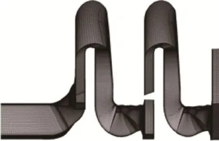
Fig. 3. CFD mesh for the single flow passage
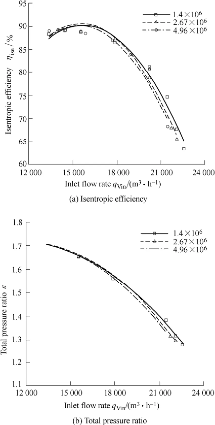
Fig. 4. CFD grid independency examination
It should be mentioned that the single flow passage model is applicable to CFD simulations away from the rotation stall point. At the rotation stall point, the full annular flow model is required for CFD simulations, which however, is beyond the scope of this work due to the computational overload.
3.3 CSD solver
The mechanical behavior of the rotating impeller is obtained through finite element analysis (FEA) on the ANSYS Workbench platform. The corresponding equation of motion in the time domain can be expressed as
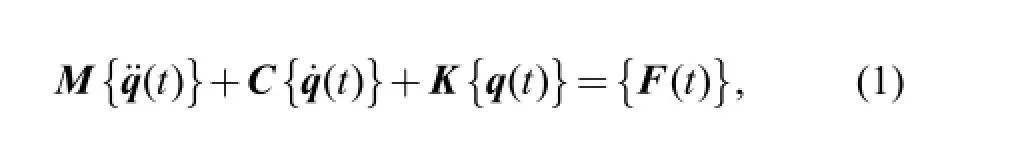
where M is the mass matrix, C is the damping matrix, K is the stiffness matrix, q is the generalized displacement vector and F is the generalized force vector which involves the centrifugal force and unsteady aerodynamic force in this study. According to the fourth strength theory[18], the von Mises stress in the blade can be calculated as
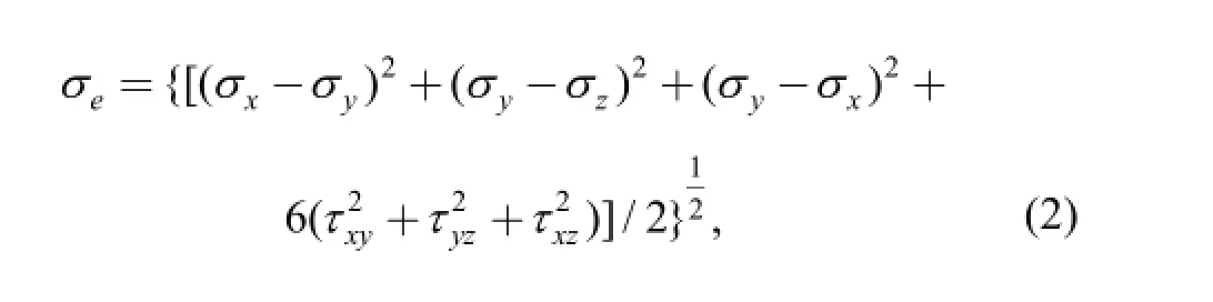
where σx, σy, and σzdenote the principal stresses while τxy,τyz, and τxzdenote the shear stresses.
Cyclic symmetric boundary conditions are applied so that only one periodic sector of the whole impeller is computed, leading to a considerable reduction of computational cost. At each time step, a distance weighted average algorithm is used for the spatial interpolation, in order to transfer and map the unsteady aerodynamic pressure from the CFD node in the flow domain to the FEA node on the blade surface. The effect of centrifugal force is considered by setting a rotational speed (i.e., 8600 r/min)for the three impellers. Besides, the fixed support is imposed on the contact part between the impeller and the shaft.
The multi-block structured FEA mesh is shown in Fig. 5. The grid independency is validated by increasing the node number until the variations of the maximum von Mises stress and deformation in each impeller are neglectable. As a result, the numbers of FEA nodes are 20 070, 20 552, and 20 096 for the first-, second-, and third-stage impellers,respectively.
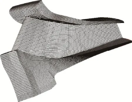
Fig. 5. FEA mesh for the impeller
3.4 Lifetime estimation approach
The nominal stress approach adopted here is based on the assumption that different components of the impeller have the same lifetime as long as they share the same material, stress concentration coefficient and load spectrum.
The rain-flow algorithm is adopted for the statistical counting of load cycles at dangerous positions where the impeller suffers the maximum mean stress or the maximum fluctuation stress. After that, the damage-equivalent load spectrum, which comprises pairs of local minima and maxima, is filtered out. Each pair of local minima and maxima represents a load cycle and exerts a damaging influence. The mean stress correction is then implemented for these filtered load cycles using the Goodman Linear model, the mathematical expression of which can be read
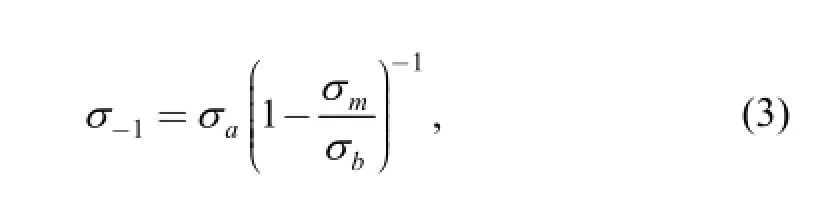
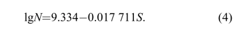
where σaand σmare the fluctuation stress and mean stress during each load cycle, respectively, σbis the ultimate strength of FV520B (1078 MPa) and σ-1is the corrected equivalent alternating stress, which can be directly mapped onto the S-N curve of the material to quantify the impact of each load cycle on the durability. In the S-N curve, the variable S on the horizontal axis corresponds to the corrected stress σ-1in Eq. (3) while N on the vertical axis is associated with the fatigue life. From the fatigue test data of FV520B, the adopted S-N curve is derived and fitted by the following exponential function
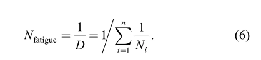
Finally, according to the linear Miner cumulative damage rule, the fatigue cumulative damage to the impeller after one cycle of the endurance test is expressed as
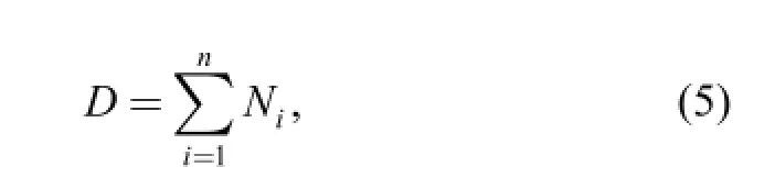
where the subscript i denotes the ith load cycle in the rain-flow counting. The number of the cycles of the endurance test to which the fatigue failure of the impeller happens can thus be derived as
4 Results and Discussion
4.1 Aerodynamic performance maps
Steady flow simulations are conducted on the pipeline centrifugal compressor over a broad range of operating points. Fig. 6 shows the aerodynamic performance map calculated at five different rotating speeds. As can be seen,the CFD results agree well with the measurement data provided by the natural gas transmission station. At the design speed of 8600 r/min, the peak isentropic efficiency is about 0.895 and the peak total pressure ratio is about 1.71. To help avoid surge and choke points in real operation,the choke line, surge line and surge control line are all marked out in the performance map, with a 5% surge margin between the surge line and the surge control line.
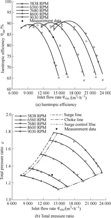
Fig. 6. Aerodynamic performance map of the compressor
4.2 Unsteady aerodynamic pressure
In order to quantify the unsteady aerodynamic force acting on compressor blades under the near-choke condition (i.e., qvin=22 065.84 m3/h) and the near-surge condition (i.e., qvin=133 43.04 m3/h) at the design speed of 8600 r/min, unsteady flow analysis is performed, whose initial solutions come from the steady simulation results in the last step. Time-varying static pressures are monitored at four typical positions (i.e., the exits of the three impellers and the outlet of the compressor) until the periodic convergence of unsteady computations is observed. Fig. 7 shows the converged pressure fluctuations with respect to the mean pressure levels at the four monitoring positions.Under near-choke and near-surge conditions, the fluctuation pressure at the impeller exit is found to gradually increase from the first- to third-stage impellers and the fluctuation pressure at the compressor outlet is significantly reduced, compared to those observed at the impeller exits. These results can be explained by the stage cumulative effect of flow unsteadiness as well as the occurrence of mixing flow within the vaneless diffuser at the last stage. Besides, Fig. 8 shows the Fast Fourier Transformation (FFT) result of the pressure fluctuation at the monitoring position at the compressor outlet. Under near-choke and near-surge conditions, the predominant frequency of pressure fluctuations is found to be equal to the blade passing frequency, i.e., 2580 Hz.
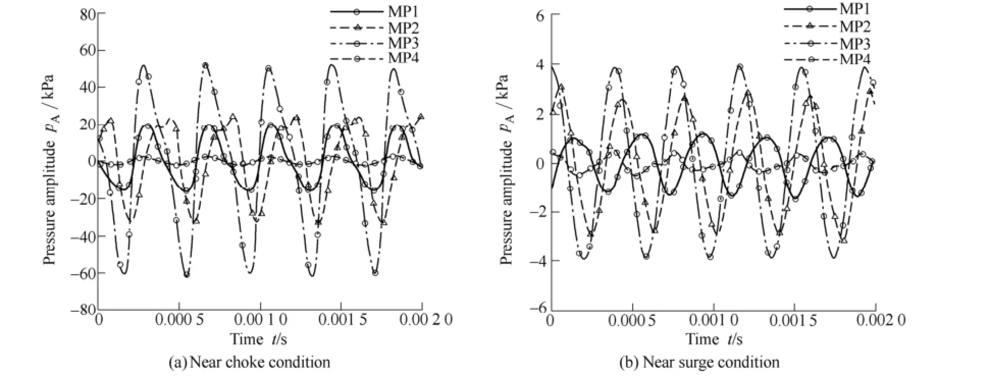
Fig. 7. Fluctuations of unsteady aerodynamic pressure at four monitoring points
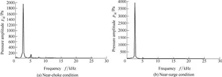
Fig. 8. Frequency-amplitude of the pressure fluctuation at the compressor outlet
4.3 Alternating stresses
After the unsteady aerodynamic pressure is obtained, FSI analysis is performed to investigate the mechanical behavior of rotating impellers under near-choke and near-surge conditions. Dangerous positions in each impeller are identified according to the obtained alternating stresses from FSI analysis. Fig. 9 shows the stress fluctuations with respect to the mean stress levels at these identified dangerous positions. In the figure, DP1 and DP2 represent the dangerous positions in the impellers with the maximum fluctuation stress and the maximum mean stress,respectively. The horizontal axis denotes the physical time steps in unsteady flow simulations. Obviously, DP1 of the third-stage impeller shows the largest fluctuation stress under near-choke or near-surge condition, followed by DP1 of the second-stage impeller. These results correspond to the variations of aerodynamic pressure fluctuations shown in Fig. 7 and can also be attributed to the stage cumulative effect of flow unsteadiness in multi-stage centrifugal compressors. The magnitudes of mean stresses and fluctuation stresses at these dangerous positions are listed in Tables 3 and 4.The impellers at latter stages are found to have relatively small mean stresses although they show larger fluctuation stresses as compared to those at the preceding stages. The largest mean stress is observed at DP2 of the first-stage impeller. This is because the first-stage impeller has the largest radius among the three impellers to yield the largest centrifugal force. Besides, the maximum mean stress and the maximum fluctuation stress under the near-choke condition are found larger than those under the near-surge condition. This result indicates that the compressor tends to suffer more damage under the near-choke condition.
4.4 Fatigue lifetime
Since the calculated alternative stresses shown in Tables 3 and 4 are remarkably lower than the yield stress of the material (1029 MPa), the operational failure of thecompressor investigated in this study can be taken as the high cycle fatigue (HCF) failure. Therefore, it is sensible to use the nominal stress approach to estimate the compressor fatigue lifetime.
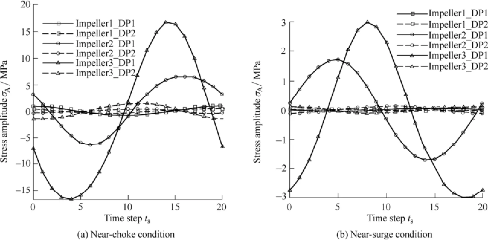
Fig. 9. Fluctuations of alternating stresses at the dangerous positions
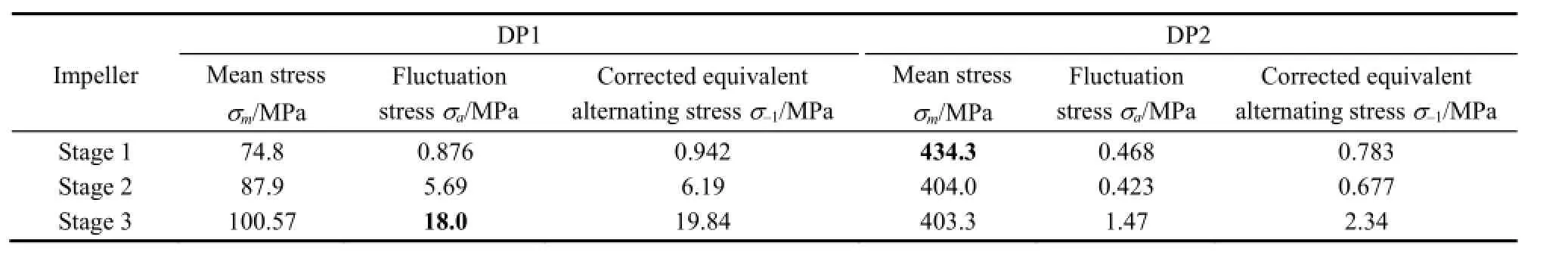
Table 3. FSI analysis results at the dangerous positions under the near-choke condition
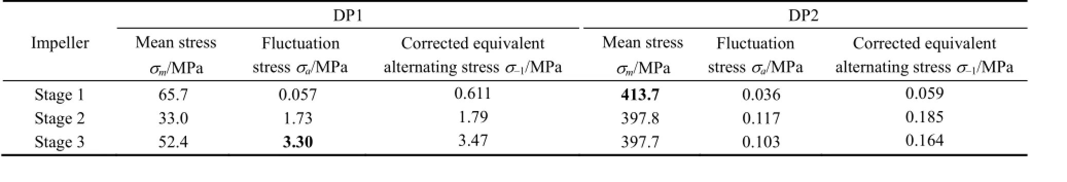
Table 4. FSI analysis results at the dangerous positions under the near-surge condition
It can be seen from Fig. 9(a) that each dangerous position has a single fundamental load spectrum and thus only a pair of local minima and maxima can be extracted to calculate the corrected equivalent alternating stress σ-1in Eq. (3). The corresponding results are also listed in Tables 3 and 4. Compared to the positions with the maximum mean stress (DP2), the positions with the maximum fluctuation stress (DP1) are found to have larger equivalent alternating stresses under either near-choke or near-surge condition,indicating that the unsteady aerodynamic pressure has a dominant effect on the fatigue strength of centrifugal impellers. Finally, the impeller fatigue lifetime under the near-choke or near-surge condition is determined by substituting the equivalent alternating stresses of each impeller into Eq. (4). The calculated results are listed in Table 5. It can be seen that under near-surge and near-choke conditions, the third-stage impeller has the shortest fatigue lifetime and that the most dangerous position of each impeller is generally located near the blade leading edge. These findings actually agree with the compressor HCF failures reported in Refs. [15-16, 19-20], which were induced by initial cracks at the blade leading edge. Besides,the impellers operating under the near-choke condition tend to be more vulnerable to damage because of the irrelatively short fatigue life. The compressor can run up to 102.7 h under the near-choke condition and 200.2 h under the near-surge condition.
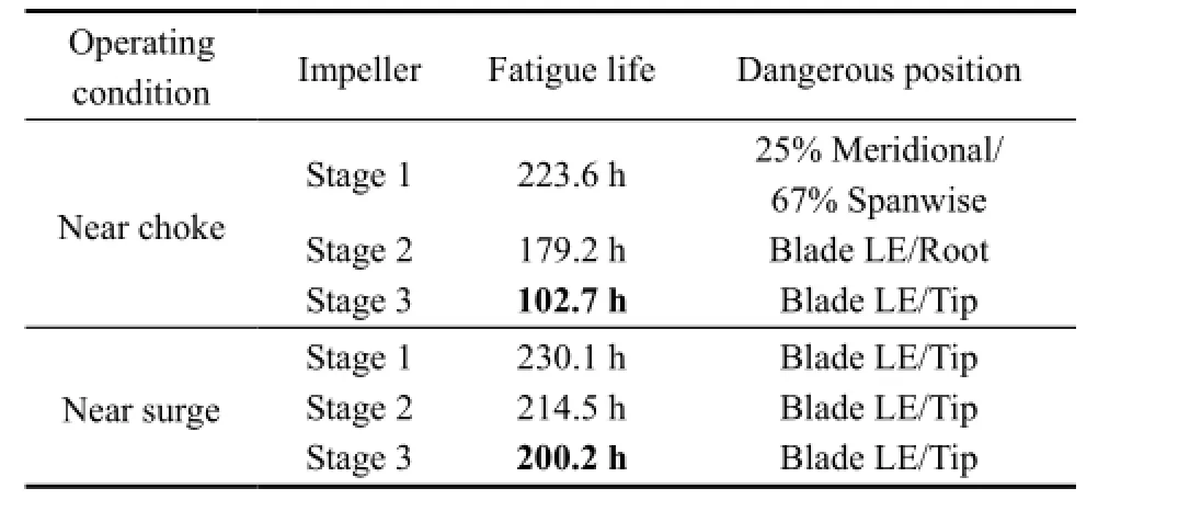
Table 5. The predicted fatigue life of the impellers
5 Conclusions
(1) Unsteady flow simulations are performed on a three-stage natural gas pipeline centrifugal compressor.Under near-choke and near-surge conditions, the fluctuation pressure at the impeller exit gradually increases from the first- to third-stage impellers and the fluctuation pressure at the compressor outlet is significantly reduced,compared to those observed at the impeller exits. The predominant frequency of pressure fluctuations is equal to the blade passing frequency, i.e., 2580 Hz.
(2) The alternating stresses induced by the unsteady aerodynamic force and centrifugal force in impeller blades are obtained based on the one-way coupling FSI model. The impellers at latter stages are found to have larger fluctuation stresses but smaller mean stresses than those at preceding stages under near-choke and near-surge working conditions. The magnitudes of the maximum mean stress and maximum fluctuation stress under the near-choke condition are larger than those under the near-surge condition.
(3) Based on the results of FSI analysis, lifetime estimation is performed on each rotating impeller to determine the survivability of the compressor subjected to both centrifugal force and unsteady aerodynamic force. Under near-choke and near-surge conditions, the most dangerous position is generally located near the blade leading edge of the third-stage impeller. Presumably, the compressor can run up to 102.7 h under the near-choke condition and 200.2 h under the near-surge condition.
[1] BURKLIN C E, HEANEY M. Natural gas compressor engine survey for gas production and processing facilities[R]. H68 Final Report. Eastern Research Group, Inc., Morrisville, North Carolina,2006.
[2] BOUSQUET Y, CARBONNEAU X, DUFOUR G, et al. Analysis of the unsteady flow field in a centrifugal compressor from peak efficiency to near stall with full-annulus simulations[J]. International Journal of rotating machinery, 2014 (2014): Article ID 729629.
[3] DICKMANN H P, WIMMEL T S, SZWEDOWICZ J, et al. Unsteady flow in a turbocharger centrifugal compressor: three-dimensional computational fluid dynamics simulation and numerical and experimental analysis of impeller blade vibration[J]. Journal of Turbomachinery, 2006, 128: 455-465.
[4] XIE Rong, GUAN Liang, HAO Muting. Numerical analysis for blade loading of centrifugal compressor under multi-operating conditions[J]. Information Technology Journal, 2014, 13(2): 286-293.
[5] Zhou Li, Xi Guang. Numerical study on the unsteady interaction flow in a centrifugal compressor stage[J]. Chinese Journal of Mechanical Engineering, 2004, 17(4): 609-613.
[6] DOWELLl E H, HALL K C. Modeling of fluid-structure interaction[J]. Annual review of Fluid Mechanics, 2001, 33: 445-490.
[7] HOU G, WANG JIN, LAYTON A. Numerical methods for fluid-structure interaction-a review[J]. Communications in Computational Physics, 2012, 12(2): 337-377.
[8] LI Xuefeng, HUANG Xiuquan, LIU Chao. Numerical simulation method for fluid-structure interaction in compressor blades[J]. Applied Mechanics and Materials, 2014, 488-489: 914-917.
[9] YUAN Shouqi, PEI Ji, YUAN Jianping. Numerical investigation on fluid structure interaction considering rotor deformation for a centrifugal pump[J]. Chinese Journal of Mechanical Engineering,2011, 24(4): 539-545.
[10] MARSHALL J G, IMREGUN M. A review of aeroelasticity methods with emphasis on turbomachinery applications[J]. Journal of Fluids and Structures, 1996, 10: 237-267.
[11] IM H S, ZHA GC. Prediction of a transonic rotor fluid/structure interaction with a traveling wave using a phase-lag boundary condition[G]. AIAA Paper No. 2013-0422, 2013.
[12] JOHNSTON DA, CROSS C J, WOLFF J M. An architecture for fluid/structure interaction analysis of turbomachinery blading[G]. AIAA Paper No. 2005-4013, 2005.
[13] IM H S, ZHA G C. Simulation of non-synchronous blade vibration of anaxial compressor using a fully coupled fluid/structure interaction[G]. ASME Paper No. GT2012-68150, 2012.
[14] LERCHE A H, MOORE J J, FENG Y S. Computational modeling and validation testing of dynamic blade stresses in a rotating centrifugal compressor using a time domain coupled fluid-structure computational model[G]. ASME Paper No. GT 2010-22216, 2010.
[15] LERCHE A H, MOORE J J, WHITE N M, et al. Dynamic stresses prediction in centrifugal compressor blades using fluid structure interaction[G]. ASME Paper No. GT 2012-69933, 2012.
[16] MAO Yijun, QI Datong, XU Qingyu. Fatigue analysis and lifetime estimation of centrifugal compressor impeller blades[G]. ASME Paper No. GT 2009-59026.
[17] ZEMP A, KAMMERER A, ABHARI R S. Unsteady computational fluid dynamics investigation on inlet distortion in a centrifugal compressor[J]. Journal of Turbomachinery, 2010, 132: 031015.
[18] JAMES M G, Barry J G. Strength of materials[M]. Beijing: Mechanical Industry Press, 2011.
[19] EJAZ N, SALAM I, TAUQIR A. Fatigue failure of a centrifugal compressor[J]. Engineering Failure Analysis, 2007, 14(7): 1313-1321.
[20] NAKHODCHI S, MAMAN E S. Fatigue life prediction in the damaged and un-damaged compressor blades[J]. Engineering Solid Mechanics, 2014, 2(1): 43-50.
Biographical notes
JU Yaping, born in 1987, is currently a lecturer at School of Energy and Power Engineering, Xi'an Jiaotong University, China. She received her PhD degree from Xi'an Jiaotong University,China, in 2013. Her research interests include fluid machinery internal flow theory and optimization design method.
Tel: +86-29-82668723; E-mail: yapingju@mail.xjtu.edu.cn
LIU Hui, born in 1987, is currently an engineer at Shanghai Marine Equipment Research Institute, China. He received his master degree from Xi'an Jiaotong University, China, in 2013.
Email: huiliu119@foxmail.com
YAO Ziyun, born in 1978, is a senior engineer at Petro China Beijing Gas Pipeline Ltd., China.
Email: zyyao@petrochina.com.cn
XING Peng, born in 1989, is currently a postgraduate student at School of Energy and Power Engineering, Xi'an Jiaotong University, China.
Email: xingpengxp@stu.xjtu.edu.cn
ZHANG Chuhua, born in 1967, is currently a professor at School of Energy and Power Engineering, Xi'an Jiaotong University,China. His main research interests include fluid machinery internal flow theory, optimization design method, and parallel CFD algorithm.
Tel: +86-29-82663539; E-mail: chzhang@mail.xjtu.edu.cn
10.3901/CJME.2015.0924.115, available online at www.springerlink.com; www.cjmenet.com; www.cjme.com.cn
* Corresponding author. E-mail: yapingju@mail.xjtu.edu.cn
Supported by National Natural Science Foundation of China(Grant No. 51406148), National Science Technology Support Program of China(Grant No. 2012BAA08B06), and Postdoctoral Science Foundation of China(Grant No. 2014M552444)
© Chinese Mechanical Engineering Society and Springer-Verlag Berlin Heidelberg 2015
September 15, 2014; revised May 11, 2015; accepted September 24, 2015
杂志排行

Chinese Journal of Mechanical Engineering的其它文章
- Influence of Alignment Errors on Contact Pressure during Straight Bevel Gear Meshing Process
- Shared and Service-oriented CNC Machining System for Intelligent Manufacturing Process
- Material Removal Model Considering Influence of Curvature Radius in Bonnet Polishing Convex Surface
- Additive Manufacturing of Ceramic Structures by Laser Engineered Net Shaping
- Kinematics Analysis and Optimization of the Fast Shearing-extrusion Joining Mechanism for Solid-state Metal
- Springback Prediction and Optimization of Variable Stretch Force Trajectory in Three-dimensional Stretch Bending Process