Propagation of Electromagnetic Wave in Coaxial Conical Transverse Electromagnetic Wave Cell
2015-11-01LIUXingxunZHANGTaoandQIWangquan
LIU Xingxun*, ZHANG Tao and QI Wangquan
1 School of Electrical Engineering and Automation, Tianjin University, Tianjin 300072, China2 Beijing Institute of Radio Metrology and Measurement, Beijing 100854, China
Propagation of Electromagnetic Wave in Coaxial Conical Transverse Electromagnetic Wave Cell
LIU Xingxun1,2,*, ZHANG Tao1, and QI Wangquan2
1 School of Electrical Engineering and Automation, Tianjin University, Tianjin 300072, China
2 Beijing Institute of Radio Metrology and Measurement, Beijing 100854, China
In order to solve the problem of broadband field probes calibration with only selected discrete frequencies above 1 GHz, a sweep-frequency calibration technology based on a coaxial conical(co-conical) cell is researched. Existing research is only qualitative because of the complexity of theoretical calculations. For designing a high performance cell, a mathematic model of high-order modes transmission is built according to the geometrical construction of co-conical. The associated Legendre control functions of high-order modes are calculated by using recursion methodology and the numerical calculation roots are presented with different half angles of inner and outer conductor. Relationship between roots and high-order modes transmission is analyzed, when the half angles of inner conductor and outer conductor are θ1=1.5136° and θ2=8° respectively, the co-conical cell has better performance for fewer transmitting high-order modes. The propagation process of the first three transmitting modes wave is simulated in CST-MWS software from the same structured co-conical. The simulation plots show that transmission of high-order modes appears with electromagnetic wave reflection, then different high-order mode transmission has different cut-off region and each cut-off region is determined by its cut-off wavelength. This paper presents numerical calculation data and theoretical analysis to design key structural parameters for the co-conical transverse electromagnetic wave cell(co-conical TEM cell).
coaxial conical TEM cell, high-order mode, cutoff wavelength
1 Introduction*
As field probes are being developed in the direction of broadband, the problem of broadband calibration in field probes becomes a serious issue. Currently, calibration of field probes is dependent on building a standard field according to the IEEE standard 1309-2005 “ IEEE standard for calibration of electromagnetic field sensors and probes,excluding antennas, from 9 kHz to 40 GHz ”[1]. A standard field is respectively established in TEM cell[2-3]and GTEM cell[4]with frequency 10 kHz-1 GHz, and in microwave anechoic chamber with frequency 1 GHz-40 GHz. Probes calibration in the microwave anechoic chamber, ten standard gain horn antennas covered together the whole frequency band which is measured for obtaining accurate gain firstly, and then used to produce a standard field. In the process of calibration, the antennas must be replaced one by one because of the narrow frequency band. Because of the cumbersome calibration methods, the period for probes calibration is very long and that only selected discrete frequencies can be operated.
In order to solve the problem above, a co-conical TEM cell of an electromagnetic guiding system for electric signals and power was first developed at NIST(National Institute of Standards and Technology), America in 1999,which was used for RF field standard system[5-6]. Compared with air-filled rectangular coaxial transmission line structures(TEM cells) or flared TEM(GTEM) cells, the new co-conical line field standard is capable of performing an accurate broadband probe calibration with frequency from 10 MHz to 40 GHz. The co-conical line field standard takes place of these techniques at a considerable savings in capital facilities and realizes sweep frequency calibration. Therefore it has wide range of potential applications in the future.
The structure design of co-conical is the key determining the accuracy of probes calibration, because half angles of internal conductor and external conductor determine the cell's characteristic impedance and the number of transmitting high-order modes. The transmission of high-order modes inside the conical chamber can cause resonance and then a loss of energy, which further will seriously hurt the stability and uniformity of standard field. Hence, research of the relationship between half angles of conductors and propagation of high-order modes in chamber is very significant. Co-conical TEM cell for the probes calibration is a relatively new technology in United States, and few numerical data on the cutoff frequency of the present high-order modes is published by WEIL C M, et al[7], from NIST, America in 2001, however the results are quite limited. For research purpose, some ideas from other conical waveguide equipment[8-9]and bi-conical antenna[10-12]design are used for reference. The theoretical foundation for designing waves guided within conical structures is from SCHELKUNOFF S A's theory[13-15]. Based on the theory, STANIER J, et al[16], conducted a theoretical analysis on hybrid modes in a dielectric lined conical waveguide. JAMES G L, et al[17], analyzed the relationship between waveguide discontinuities and transmission of modes. DIRK I L[18]from Stellenbosch University in South Africa described some theoretical calculation data of cutoff modes about conical transmission line power combiners with half angle of outer conductor being 90° in 2007. In China CUI Furong, et al[19-21]from South China University of Technology utilized finite difference time domain(FDTD) methodology to analyze the uniformity of field in co-conical TEM cell which was designed with half angles of inner conductor and outer conductor being 15° and 30° respectively, and established its working frequency upper limit being 3 GHz.
Even though some researches have been done on conical structured waveguide equipment by some domestic and international experts, very limited numerical data is provided because of the complicacy of the calculations required. In the paper, a thorough theoretical analysis of co-conical geometry is presented for designing highperformance co-conical TEM cell. A complete mathematical description, including Legendre function computation and numerical data, of the cutoff frequency of high-order modes is given. Consequently, a new structure of co-conical transmission lines is designed with better performance and the simulated results about field distributions of the high-order modes are obtained by CST-MWS.
2 Geometrical Construction of Co-conical
The geometrical construction of co-conical transmission line is shown in Fig. 1. It is mainly composed of inner conductor, outer conductor, impedance match, connector,termination and absorber. Generator injects signal into co-conical through connector. There is an electromagnetic field existing between inner conductor and outer conductor. The impedance match section is designed for matching the nominal 50 Ω used by the excitation source, coaxial feed cable and connector to the line impedance value. Termination and absorber is used to absorb the traveling electromagnetic wave and then to reduce the wave reflection, which is help to make a homogeneous field at the text volume section for accurate probe calibration. In addition, maintaining the dominant TEM mode structure,reducing losses, and preventing generation of high-order modes is also an important factor for obtaining uniform field. Therefore, numerical model of high-order mode in the line is presented and the process of propagation is analyzed.
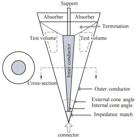
Fig. 1. Geometrical construction of co-conical TEM cell
3 Numerical Model of High-order Modes
The co-conical transmission line is analyzed using the spherical coordinate system. The geometry of a conical transmission line as well as the definition of the spherical coordinate system is shown in Fig. 2. The feed point of the line is set to origin, which is the coincidence peak of the two cones. The half angles of inner conical conductor and outer conical conductor are described by θ1and θ2respectively. Based on the SCHELKUNOFF's theory[13-15],the transcendental equations of modal cutoff in co-conical are presented here.
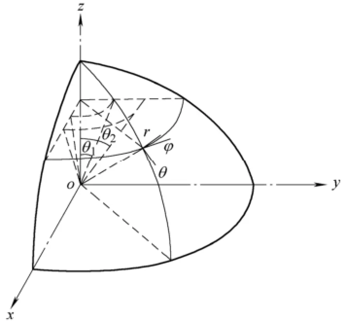
Fig. 2. Ceometry of co-conical in spherical coordinate
3.1 Transverse electric(TE) mode
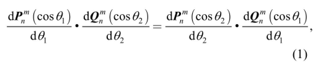
For a TE spherical wave propagating in the region between two coaxial conical conductors, the modal cut-off is defined by the following relationship[17-18]:
3.2 Transverse Magnetic(TM) mode
For a TM spherical wave propagating in the region between two coaxial conical conductors, the modal cut-off is controlled by the following equation[15,18]:
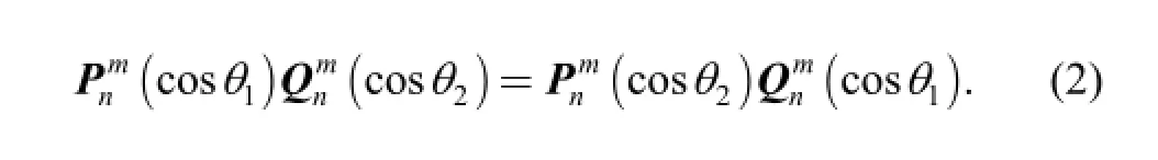
4 Numerical Evaluation of High-order Mode
4.1 Recursion method
In order to obtain numerical results for the field distributions of the high-order modes in co-conical TEM cell, the transcendental Eqs. (1) and (2) have to be solved for the function root. Because of the much complex analytic expression of Legendre functions, it's hard to obtain the solution directly. There are some recursions used for simplifying the calculation.
The recursions of associated Legendre functions are as follows[22]:
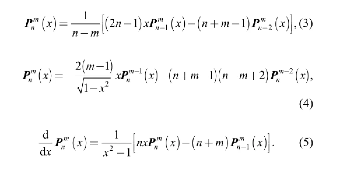
These recursions are also suitable for the second kind associated Legendre function. The starting values can be calculated from the known polynomials[22-24]just as follows:
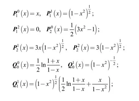
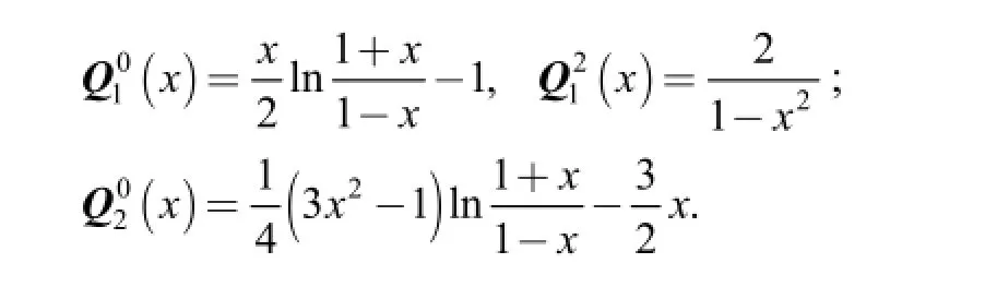
Therefore the expression of high-order Legendre functions can be deduced.
4.2 Calulation results
In order to obtain a suitable size of calibration space and little high-order modes, a co-conical transmitting line is designed with the half angles being θ1=1.513 6°, θ2=8°,respectively. A calculation program is made using the numerical software Matlab 6.5 in iteration method. n is the integral with range 0-80, and m=0, 1, 2 respectively. The results of the co-conical transmitting line for high-order modes as compared with its values designed by NIST with the half angles being θ1=1.893°, θ2=10° are as follows.
4.2.1 Results of co-conical with θ1=1.513 6°, θ2=8°
Result values of Eqs. (1) and (2) are expressed in y. The first three order result curves(m=0, 1, 2) of transcendental Eqs. (1) and (2) are shown in Fig. 3 and Fig. 4.
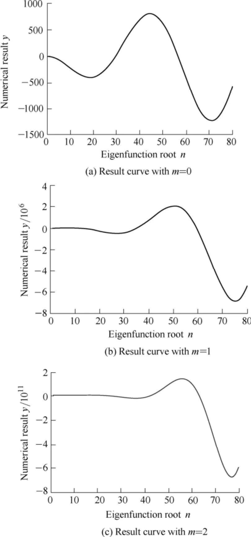
Fig. 3. Result curves of Eq. (1) with θ1=1.513 6°, θ2=8°
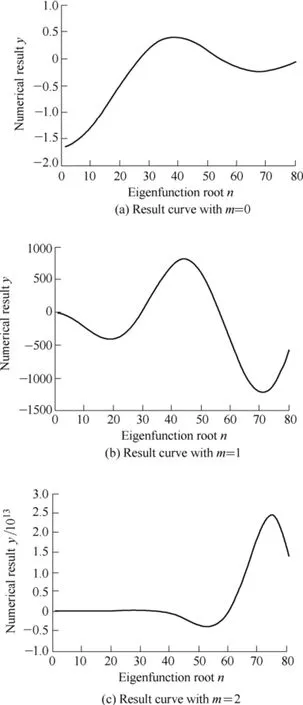
Fig. 4. Result curves of Eq. (2) with θ1=1.513 6°, θ2=8°
The number of cross points that the curve crosses with y=0 coordinate axis represent the number of roots of function. For example, in Fig. 3 there have two roots ν01and ν02with m=0, 3 roots ν11, ν12and ν13with m=1 and 4 roots ν21, ν22, ν23and ν24with m=2. Roots of Eqs. (1) and (2)are listed in Tables 1 and 2 separately.
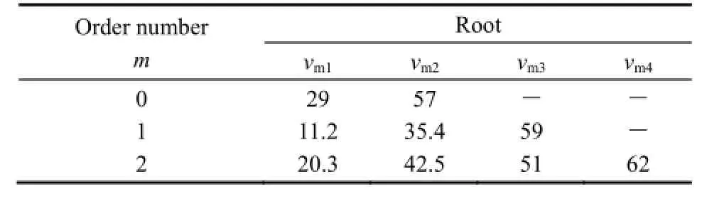
Table 1. Roots of Eq. (1)
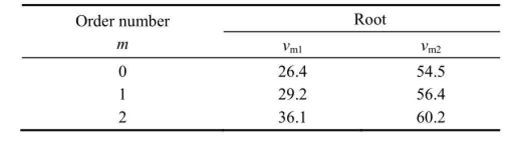
Table 2. Roots of Eq. (2)
4.2.2 Results of co-conical with θ1=1.893°, θ2=10°
The first three order result curves(m=0, 1, 2) of transcendental Eqs.(1) and (2) are shown in Fig. 5 and Fig. 6.
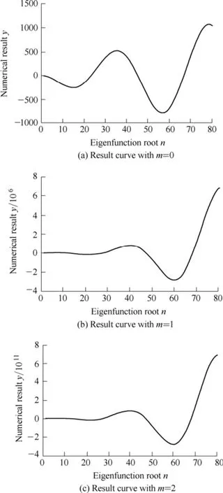
Fig. 5. Result curves of Eq. (1) with θ1=1.893°, θ2=10°
The roots of Eqs. (1) and (2) are listed in Tables 3 and 4 separately.
The number of roots represents the number of high-order modes. The more of the roots, the more high-order modes can propagate in the co-conical TEM cell. To improve the quality of standard field in conical chamber, amount of modes must be reduced. From the result above, the characteristic of co-conical TEM cell with θ1=1.513 6°,θ2=8° is better than that with θ1=1.893°, θ2=10°, because of few modes.
4.3 Cutoff frequency of high-order mode
The cutoff frequency for high-order modes in the co-conical line is given by
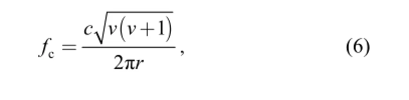
wherec
f—Cutoff frequency of high-order modes,
r—Distance between cone feed and measure point,
ν—Roots of transcendental Eqs. (1) and (2)for the TE and TM mode respectively,
c—Speed velocity of wave in free space.
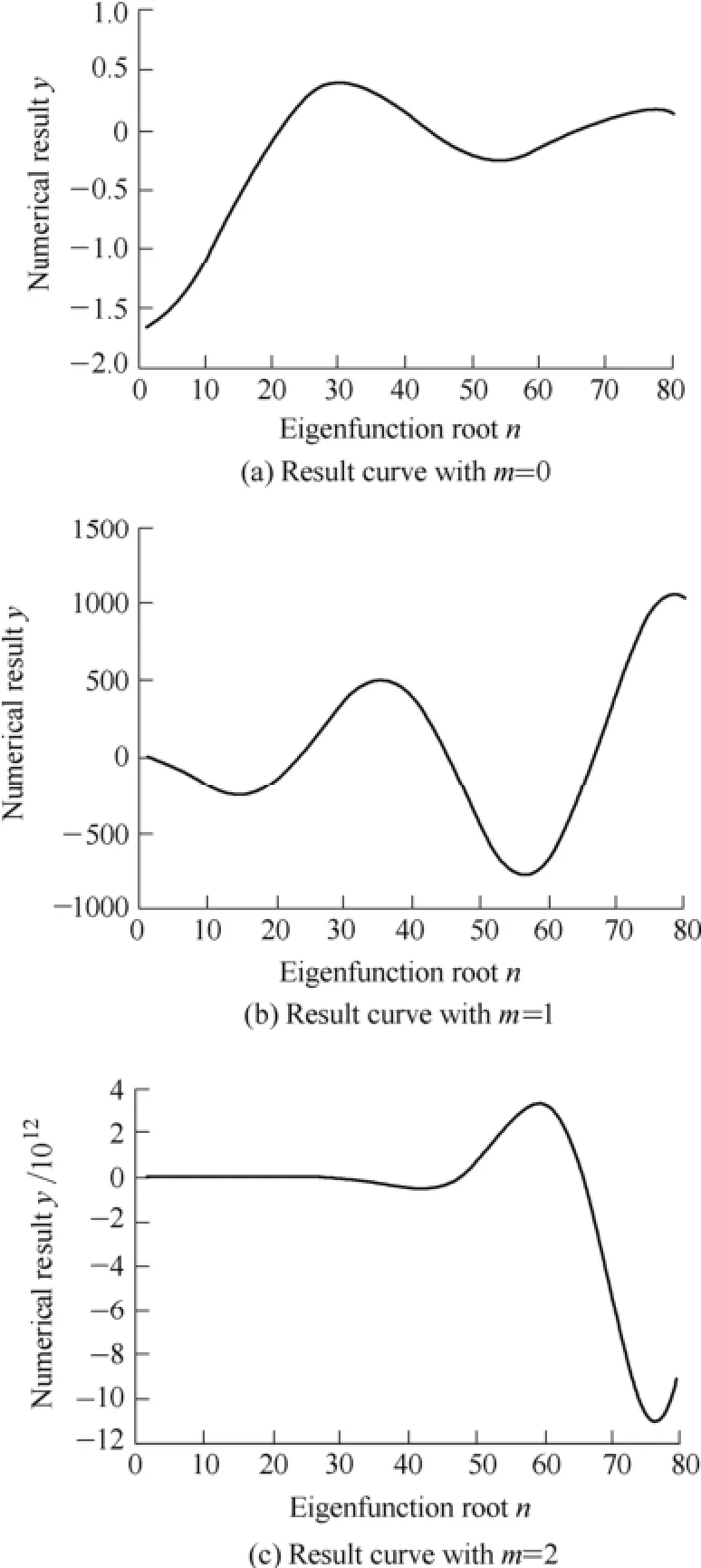
Fig. 6. Result curves of Eq. (2) with θ1=1.893°, θ2=10°
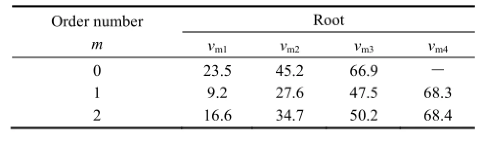
Table 3. Roots of Eq. (1)
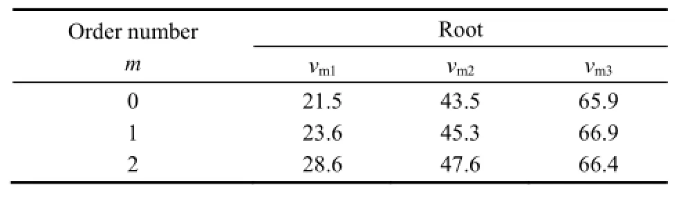
Table 4. Roots of Eq. (2)
Depending on the roots and Eq. (6) above, when the half angles of inner conductor and outer conductor of the co-conical TEM cell are θ1=1.513 6° and θ2=8°, the cutoff wave length of the high-order modes is obtained as shown in Fig. 7. The first high-order mode is TE11with the longest cutoff wavelength 0.53r. The cutoff zone is the district that wavelength is longer than the cutoff wavelength of TE11. In the region, the high-order modes can be non-propagating and only TEM wave propagating λc of the mode is relative to r, therefore there is a gradual transition for mode from the non-propagating to the propagating region. The point of gradual cutoff of a mode is not only dependent on frequency, but also on the spatial coordinates.
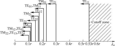
Fig. 7. Cutoff wavelength of high-order modes in co-conical TEM cell
For the co-conical TEM cell with θ1=1.513 6°, θ2=8°,the position for calibration is decided by space at the place r=1.8 m. When r=1.8 m the cutoff frequency of several main high-order modes for TE wave and TM wave are shown in Table 5 in order.
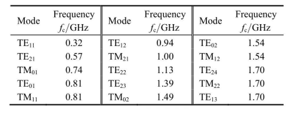
Table 5. Cutoff frequency of high-order modes
5 Modal Plots
From Table 6, some high-order modes have lower cutoff frequencies. If the work frequency is from 200 MHz-40 GHz, high-order modes can transmit in the co-conical TEM cell. The transmission characteristics of high-order modes are discussed in the next.
In order to analyze the transmission characteristic, the CST-MWS software is used for simulating the process of electromagnetic wave propagation. Geometry consistent with the proposed co-conical structure will be chosen. The impedance of Z0is equal to 75 Ω with θ1=1.5136°, θ2=8°. The outer radius of the line is chosen as r which is equal to 180 mm. There are two ports which are designed as waveguide. The small one is port 1 from which the signal is injected. The big one is port 2 that is terminated by load.
5.1 Traveling wave
Field plots of the first three modes at frequency 1 GHzare as follows.
The simulation result plot for TEM wave is presented in Fig. 8. TEM wave can transmit in the co-conical TEM cell without cutoff frequency. When the signal is injected from port 1, TEM wave transmit along with r direction. The wave is reflected at opposition direction from port 2 if there are poor absorbers in port 2. It very clearly illustrates TEM wave can propagate at all region of cavity.
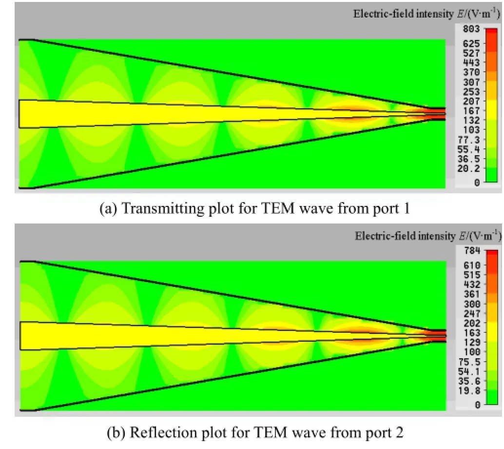
Fig. 8. Simulation result plot for TEM wave transmission
In Figs. 9 and 10 the traveling wave properties of the higher order modes are clearly visible. The modes do not propagate when signal being injected from port 1, they however shall produce a strong field of reflection wave from port 2. Large fields exist in the propagating regions. The point of gradual cutoff of a mode is dependent on frequency and the spatial coordinates. The cutoff radius(a mode is the minimum radius where the mode is propagating at a certain frequency) of TE21is longer than that of TE11, therefore the position of TE21reflection field is closer to port 2 compared with TE11.
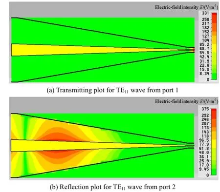
Fig. 9. Simulation result plot for TE11wave transmission
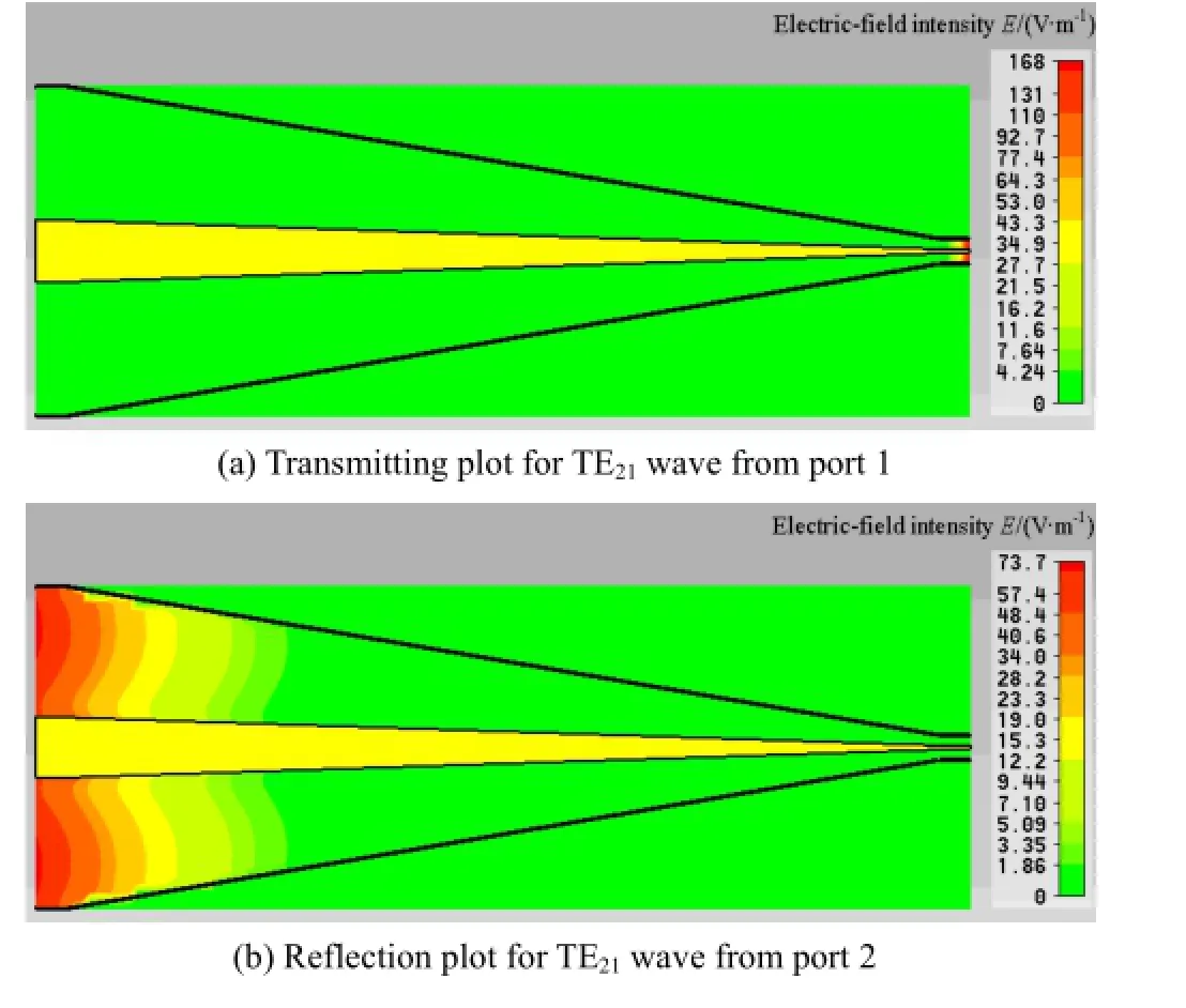
Fig. 10. Simulation result plot for TE21wave transmission
5.2 Standing wave
The field patterns of electromagnetic wave are shown in Figs. 11 to 13. The wave fronts of these modes are visible along the r-axis.
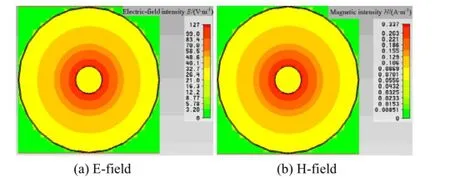
Fig. 11. TEM modal fields at 1GHz
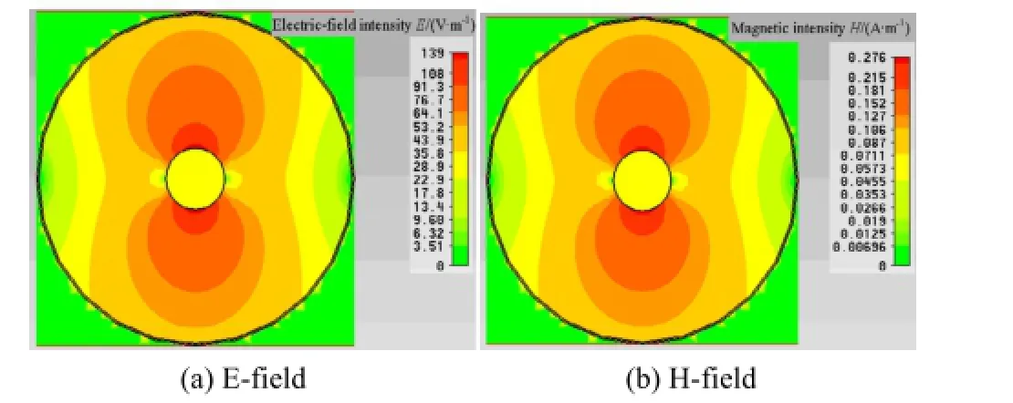
Fig. 12. TE11modal fields at 1GHz
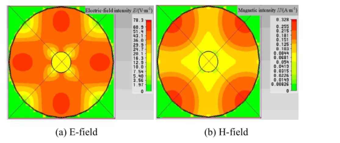
Fig. 13. TE21modal fields at 1 GHz
For TEM wave, the amplitude of field is centrosymmetry by inner conductor and decreases gradually from inner to outer. The amplitude of TE11field is axiallysymmetry and it is more complex for TE21field. Therefore the standing waves of high-order modes affect the field uniformity of TEM wave. In order to control the transmission of high-order modes, a good match is important for reducing reflection.
6 Conclusions
(1) According to the numerical analysis of high-order mode, the number of high-order modes with θ1=1.5136°,θ2=8° is obviously fewer than that with θ1=1.893°, θ2=10°,which means the performance of the standard field produced in the previous structured co-conical TEM cell is better.
(2) From the simulation, when signal is injected in port 1,there is none of high-order modes transmission because of good match and absorbers in port 2. The E-field of TEM is only θ-directed, and the H-field have no component in the θ-direction.
(3) If the reflection wave from port 2 exists, high-order modes propagate at propagating regions that the radius is bigger than the cutoff radius of modes. Strong fields of standing wave are produced.
(4) The higher order of mode, the more complex field of mode is in existence and then uniformity of TEM field may be destroyed. Reflection is one important reason for high-order modes appearance.
[1] Standards Development Committee of the IEEE Electromagnetic Compatibility Society, American National Standards Institute. IEEE Std 1309TM-2005 IEEE Standard for Calibration of Electromagnetic Field Sensors and Probes, Excluding Antennas,from 9 kHz to 40 GHz[S]. New York: The Institute of Electrical and Electronics Engineers Inc., 2005.
[2] LUCA Ziberit, ORIANO B, MARIO C, et al. On the use of TEM cells for the calibration of power frequency electric field meters[J]. Measurement, 2010, 43(3): 1282-1290.
[3] MORIOKA T. Probe response to a non-uniform e-field in a TEM cell[C]//Conference on Precision Electromagnetic Measurements,Daejeon, Korea, June 13-18, 2010: 327-328.
[4] KANG Noweon, KANG Jinseob. Characterization method of electric field probe by using transfer standard in GTEM cell[J]. IEEE Transaction on Intrumentation and Measurement, 2009, 58(4): 1109-1113.
[5] WEIL C M, NOVOTNY D R, JOHNK R T, et al. A new broadband RF field standard using a coaxial transmission line of conical geometry: progress report[C]//Proceedings of 23rd AMTA Meeting,Denver, USA, October, 2001: 14-19.
[6] WEIL C M, NOVOTNY D R, JOHNK R T, et al. Calibration of broadband RF field probes using a coaxial conical transmission line[C]//Proceedings of 14th International Conference on Microwaves Radar and Wireless Communicationse, Boulder, USA,May 20-22, 2002: 404-407.
[7] WEIL C M, RIDDLE B F, NOVOTNY D R, et al. Modal cutoff in coaxial transmission lines of conical and cylindrical geometries[C]//IEEE MTT-S International Microwave Symposium Digest, Boulder, USA, May 20-25, 2001: 1229-1232.
[8] MARCUVITZ N. Waveguide handbook[M]. London: Peter
Peregrinus Press, 1986.
[9] BLADEL J V. The Φ0constant mode in free-space and conical waveguides[J]. IEEE Transactions on Microwave Theory and Techniques, 2002, 50(10): 1233-1237.
[10] SCHELKUNOFF S A. Theory of antennas of arbirary size and shape[J]. Proceedings of the I.R.E, 1941, 29(10): 493-521.
[11] CONSTANTINE A B. Antenna theory: analysis and design[M]. New York: John Wiley and Sons, 1982.
[12] CONSTANTINE A B. Advanced engineering electromagnetics[M]. New York: John Wiley and Sons, 2012.
[13] SCHELKUNOFF S A. Transmission theory of sperical waves[J]. AIEE Transactions, 1938: 744-750.
[14] SCHELKUNOFF S A. Transmission theory of plane electromagneitc waves[C]//Proceedings of the Institute of Radio Engineers, Vikis, September, 1937: 1457-1492.
[15] SCHELKUNOFF S A. Electromagnetic waves[M]. New York: D.Van Nostrand Company, Inc., 1943:285-289.
[16] STANIER J, HAMID M. Hybrid modes in a dielectric lined conical waveguide[J]. Electronics Letters, 1986, 22(12): 626-627.
[17] JAMES G L. On the problem of applying mode-matching techniques in analyzing conical waveguide discontinuities[J]. IEEE Transactions on Microwave Theory and Techniques, 1983, 31(9): 718-723.
[18] DIRK I L. Analysis and design of conical transmission line power combiners[D]. Cape Town: University of Stellenbosch, 2007.
[19] CUI Furong. Research and analysis of new series of transverse electromagnetic cell[D]. Guangzhou: South China University of Technology, 2000.
[20] CUI Furong, LAI Shengli, JI Fei, et al. Transmission characteristics of taper TEM cell[J]. Journal of Applied Sciences, 2001, 19(1): 10-13.
[21] CUI Furong, JI Fei, LAI Shengli, et al. Conical transverse electromagnetic cell[J]. Journal of Microwaves, 2000, 16(5): 619-623.
[22] BELL W W. Special functions for scientists and engineers[M]. New York: Dover Publications, 2013.
[23] ZHANG Shanjie. Computation of special functions[M]. New York : John Wiley and Sons Inc., 1996.
[24] ABRAMOWITZ M, STEGUN I A. Handbook of mathematical functions with formulas[M]. Washington DC: Graphs and Mathematical Tables,US Gov. Printing Office, 1966
Biographical notes
LIU Xingxun, born in 1982, is currently a PhD candidate at School of Electrical Engineering and Automation, Tianjin University, China. She received her master degree from Tianjin University, China, in 2006. She joined Tianjin Institute of Metrology, China in 2006, and joined Beijing Institute of Radio Metrology and Measurement, China, in 2010. Her research interests include electromagnetic reference field, antennas and probes calibration, EMC measurement.
Tel: +86-10-88527084; E-mail: xun_zi_jing@163.com
ZHANG Tao, born in 1964, is a professor and a doctoral tutor at Tianjin University, China. His research interests are automatic control system, fluid dynamics, and electromagnetic reference field.
Tel: +86-13902184051; E-mail: zt50@tju.edu.cn
QI Wanquan, born in 1975, received his PhD degree from Beihang University, China, in 2006. He is currently a senior engineer at Department of Electromagnetic Environment Effect, Beijing Institute of Radio Metrology and Measurement, China. His research interests include EMC test and calibration.
E-mail: qiwq@sina.com
10.3901/CJME.2015.0410.040, available online at www.springerlink.com; www.cjmenet.com; www.cjme.com.cn
* Corresponding author. E-mail: xun_zi_jing@163.com
Supported by State Administration of Science Technology and Industry for National Defense, China(Grant No. JSJC2013204B301)
© Chinese Mechanical Engineering Society and Springer-Verlag Berlin Heidelberg 2015
November 5, 2014; revised March 26, 2015; accepted April 10, 2015
杂志排行

Chinese Journal of Mechanical Engineering的其它文章
- Influence of Alignment Errors on Contact Pressure during Straight Bevel Gear Meshing Process
- Shared and Service-oriented CNC Machining System for Intelligent Manufacturing Process
- Material Removal Model Considering Influence of Curvature Radius in Bonnet Polishing Convex Surface
- Additive Manufacturing of Ceramic Structures by Laser Engineered Net Shaping
- Kinematics Analysis and Optimization of the Fast Shearing-extrusion Joining Mechanism for Solid-state Metal
- Springback Prediction and Optimization of Variable Stretch Force Trajectory in Three-dimensional Stretch Bending Process