Fuzzy Theory Based Control Method for an In-pipe Robot to Move in Variable Resistance Environment
2015-11-01LITeMAShugenLIBinWANGMinghuiandWANGYuechao
LI Te, MA Shugen, LI Bin WANG Minghui*, and WANG Yuechao
1 State Key Laboratory of Robotics, Shenyang Institute of Automation, Chinese Academy of Sciences,Shenyang 110016, China2 University of Chinese Academy of Sciences, Beijing 100049, China3 Department of Robotics, Ritsumeikan University, Shiga-ken 525-8577, Japan
Fuzzy Theory Based Control Method for an In-pipe Robot to Move in Variable Resistance Environment
LI Te1,2, MA Shugen1,3, LI Bin1, WANG Minghui1,*, and WANG Yuechao1
1 State Key Laboratory of Robotics, Shenyang Institute of Automation, Chinese Academy of Sciences,Shenyang 110016, China
2 University of Chinese Academy of Sciences, Beijing 100049, China
3 Department of Robotics, Ritsumeikan University, Shiga-ken 525-8577, Japan
Most of the existing screw drive in-pipe robots cannot actively adjust the maximum traction capacity, which limits the adaptability to the wide range of variable environment resistance, especially in curved pipes. In order to solve this problem, a screw drive in-pipe robot based on adaptive linkage mechanism is proposed. The differential property of the adaptive linkage mechanism allows the robot to move without motion interference in the straight and varied curved pipes by adjusting inclining angles of rollers self-adaptively. The maximum traction capacity of the robot can be changed by actively adjusting the inclining angles of rollers. In order to improve the adaptability to the variable resistance, a torque control method based on the fuzzy controller is proposed. For the variable environment resistance, the proposed control method can not only ensure enough traction force, but also limit the output torque in a feasible region. In the simulations, the robot with the proposed control method is compared to the robot with fixed inclining angles of rollers. The results show that the combination of the torque control method and the proposed robot achieves the better adaptability to the variable resistance in the straight and curved pipes.
screw drive, in-pipe robot, fuzzy control, torque control
1 Introduction*
Pipelines are the most economical and efficient transportation facilities in the industrial and urban systems. However, potential safety hazards exist due to the failure pipelines with age. Traditionally, the defect detection and regular maintenance in pipes are operated manually. This way is usually time-consuming and dangerous due to the hazardous substances inside pipes. Therefore, kinds of in-pipe robots have been developed to inspect pipes instead of the manual operation[1]. The robots can carry cameras to feedback fault messages and locations. The PIG type is the first in-pipe robot that is passively driven by the pressure of the fluid without driving mechanism[2]. The PIG robots are generally applied in the pipes with big diameters for enough differential pressure. Another kind of in-pipe robot with active rollers is efficient[3-5]. The screw drive type with passive rollers has a simple transmission mechanism[6-8]. The crawler type with the caterpillar mechanism has good traction performances[9]. In addition,there are three kinds of biomimetic in-pipe robots. The worm type moves by the expansion and contraction of its body[10-11]. The snake-like type moves by the anisotropic frictions of the multi-modules[12]. The walking type like a polypod needs complex control methods in the different in-pipe structure[13]. The subminiature in-pipe robots even are applied in the intestine of human bodies[14].
Compared to other kinds of robots, the screw drive in-pipe robot can achieve efficient movements with only one motor and has an advantage of miniaturization. However, few researches have been focused on the adaptability to the environment resistance, especially in curved pipes. Generally, the environment resistance includes the force produced by the friction, towing cable,gravity and spring compression. It changes a lot when the pipes are made in different materials or positioned in different postures. Therefore, the in-pipe robot can move smoothly in the pipes only if it has the ability to overcome the wide range of resistance. Apparently, the robot with good adaptability should have an enough traction force. Furthermore, we intend that the robot can also control the working points of the driving motor in a feasible region,instead of inefficient or overload regions.
So far, many screw drive in-pipe robots have been developed for the inspection in the straight or curved pipes. IWASHINA, et al[15], developed a micro screw drive in-pipe robot to move in a straight pipe of 20 mm in diameter. The inclining angle of rollers on the robot is invariable. Therefore, the maximum traction capacity is changeless and determined by the rated torque of driving motor and parameters of the robot. The robot can only adjust the output torque of motor to adapt to the variable resistance force whose adaptability is finite. LIU, et al[16],designed a modular screw drive in-pipe robot that can pass through curved pipes with the conic coil springs. This robot can obtain a good traction ability by the multiple modules. In order to improve the steering ability, KAKOGAWA, et al[17], developed a screw drive in-pipe robot with a pathway selection mechanism. Although the above robots adopt active or passive mechanisms to steer in curved pipes, they have motion interference with the inner wall of the curved pipes due to the steering velocity constraints. The maximum traction capacity is weakened by the motion interference, especially in the curved pipes. HIROSE, et al[7], developed a screw drive in-pipe robot Theseus-І based on load-sensitive continuously variable transmission(CVT)that can adjust the maximum traction capacity. However,the adjustment is unidirectional. LI, et al[18], proposed an in-pipe robot with bidirectional active control for inclining angles of rollers and the energy optimization control strategy in our previous study. However, the adjustment ability of maximum traction capacity is considered only in straight pipes. LI, et al[19], also proposed an in-pipe robot that can adaptively pass through the straight and curved pipes without motion interference. However, this robot could not actively change the maximum traction force. Therefore, it is necessary to focus on the mechanism improvement and control method in both straight and curved pipes that are the main types of the pipes.
In this paper, we will propose an in-pipe robot with the bidirectional active control ability and differential ability of the inclining angles. In order to improve the adaptability to the wide range of environment resistance, the control method is discussed. And a fuzzy control method[20-21]is adopted in consideration of the asymmetry of control law of the robot and the flexibility of fuzzy control rule selection.
This paper is organized as follows. Section 2 presents a new screw drive in-pipe robot with adaptive linkage mechanism. In section 3, the traction capacity of the robot is analyzed in consideration of the straight and curved pipes,respectively. Section 4 proposes a control method for the robot to move in variable resistance environment based on fuzzy theory. Section 5 presents and discusses the dynamic simulation results. The conclusions are listed in section 6.
2 Overview of the In-Pipe Robot with Adaptive Linkage Mechanism
2.1 Structure design
In order to improve the adaptability to environment resistance in straight and curved pipes, it is necessary for the robot to have three abilities that are the wall-pressing ability, adjustable traction ability and steering ability. The wall-pressing ability makes the robot in contact with the wall of pipes, which is important for the robot to obtain traction. Generally, the elastic arm mechanism is adopted as the wall-pressing mechanism in the screw drive in-pipe robots. Our previous study has proposed a method of changing the traction force by adjusting the inclining angle of rollers in the straight pipes. Therefore, our attention is focused on adjustable traction ability and steering ability without motion interference in the curved pipes.
The velocity component of each roller with fixed inclining angle cannot be adjusted independently. Motion interference is resulted from the unmatched velocities of rollers in the steering motion. The traction capacity weakens due to the internal motion interference as that often happens in vehicles.
Therefore, a new screw drive in-pipe robot with adaptive linkage mechanism is proposed as shown in Fig. 1. The robot is composed of the rotator unit and the stator unit. The stator unit with a driving motor provides power for the rotator unit. Three elastic arms are mounted on the shell by 120 degree apart of each other.
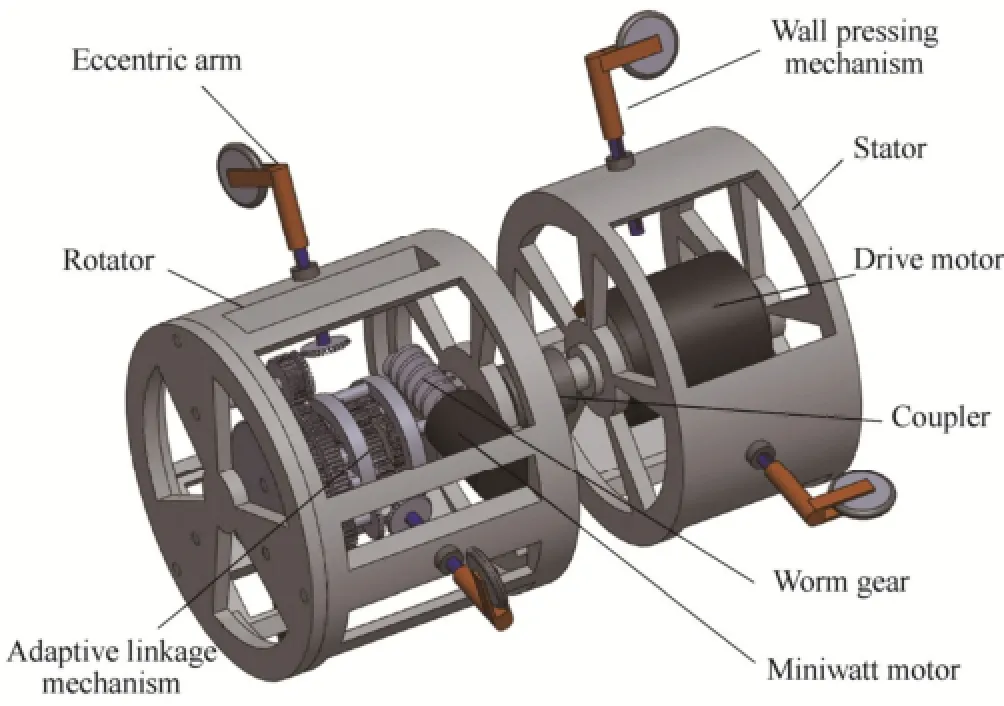
Fig. 1. Structure of the robot
The rotator unit rotates to generate the traction force. There are also three elastic arms mounted on the shell symmetrically. Differently, each passive roller on the end of the elastic arm has an inclining angle. The adaptive linkage mechanism based on the tri-axial differential mechanism is driven by a miniwatt motor and mounted inside the shell. The outputs of the adaptive linkage mechanism can change the inclining angles of the rollers in order to adapt to different pipe environments.
The mechanism schematic diagram of the robot is shown in Fig. 2. The robot has three working modes based on the adaptive linkage mechanism.
Mode 1: Straight motion mode. In the straight pipe, the forces acted on the rollers are the same and the adaptive linkage mechanism does not work. The robot moves by the screw drive mechanism.
Mode 2: Steering motion mode. In the curved pipe, the forces acted on the rollers are changing in real time.Therefore, the inclining angles of rollers are adjusted by the adaptive linkage mechanism to change the speed of each roller.
Mode 3: Traction adjustment mode. The miniwatt motor works to change all inclining angles in order to adapt to the variable environment resistance.
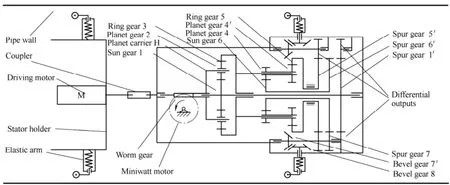
Fig. 2. Mechanism schematic diagram
2.2 Elastic arm mechanism
The elastic arm mechanism can make the robot in contact with the inner wall no matter how the structure of the pipe changes. The elastic arm mechanism on the stator unit is shown in Fig. 3(a). It consists of the slider, sliding block, casing, compression spring and passive rollers. The slider design allows the robot to move in the pipes with different diameters. And the robot can adapt to the structure changes in the curved pipes.
Fig. 3(b) shows the elastic arm mechanism with an additional bevel gear and bearing on the rotator unit. The bearing allows a rotational freedom of the inclining angle. The bevel gear is mounted on the tip and connected with the adaptive linkage mechanism. The axis center of the passive roller on the eccentric arm is not in the line of the elastic arm. The eccentric arm is used to feedback the force acted on the rollers.
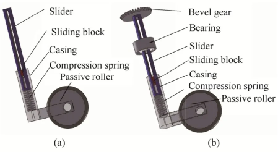
Fig. 3. Elastic arm mechanism
2.3 Design of adaptive linkage mechanism
The adaptive linkage mechanism is an under-actuated system and designed based on a tri-differential mechanism. The inclining angles of the rollers on the tips of elastic arms are controlled by the adaptive linkage mechanism.
The detailed mechanism transmission relationship can be seen in the exploded view as shown in Fig. 4. The shell of the miniwatt motor is fixed on the rotator and the output axis connects with the planet carrier H of the first planetary gear train by the worm gear. The worm gear makes the power transmit uniaxially. Sun gear 1 is the first differential output. Ring gear 3 connects with planet carrier H2 of the second planetary gear train. Planet gear 4 and 4′ are amounted on the planet carrier H2 with bearings. Sun gear 6 and ring gear 5 are the second and the third differential outputs. Then the three outputs transmit power to corresponding elastic arms through spur gears.
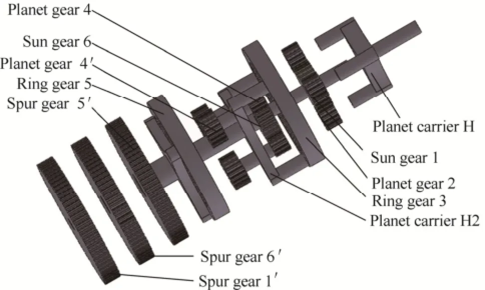
Fig. 4. Exploded views of adaptive linkage mechanism
In order to obtain symmetrical differential outputs, the proper numbers of the gear tooth should be selected as
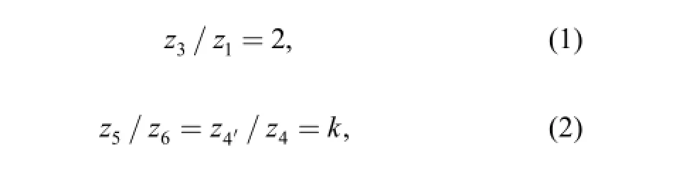
where i represents the index of a gear and ziis the number of the tooth for the ith gear. k denotes a constant.
Considering the angular velocity relationship, we can obtain the relationship between the input and output angular velocities:
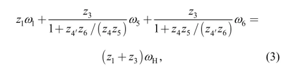
where ωidenotes the angular velocity of the ith gear.
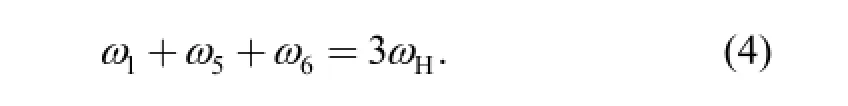
Substituting Eqs. (1) and (2) into Eq. (3), we can obtain a simplified and symmetrical angular velocity relation
i5/8denotes the transmission ratio between the differential mechanism outputs and the bevel gear related with the angles of the rollers. It can be calculated by
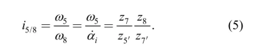
Substituting Eq. (5) into Eq. (4), the angular speed relation between the input motor and inclining angles of rollers can be written down as
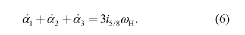
The integral of Eq. (6) can be expressed by
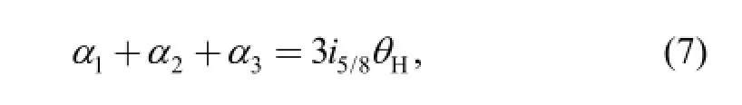
where θHis the rotation angle of planet carrier H.
3 Traction Capacity Analysis
The traction capacity of the robot determines the adaptability to the environment resistance. It is necessary to obtain the relations between the traction and the inclining angles in preparation for the control. The situations in the straight pipes and curved pipes are discussed here,respectively.
3.1 Traction computation in straight pipes
In order to simplify the force model in the straight pipe,ignore the radial component of the gravity. Then the structure of the robot is symmetrical. As shown in Fig. 5,the equivalent axis resistance is denoted as Fa. The inclining angle of each roller αiis equal to the input angle 0αof the adaptive linkage mechanism. The force relationship can be expressed as
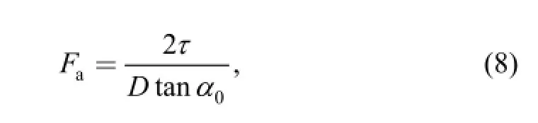
s.t.
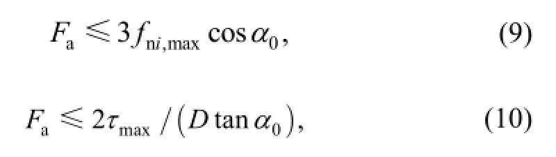
where τ, D and fni,maxrespectively denote the output torque of the motor, the pipe diameter and the maximum static friction force.
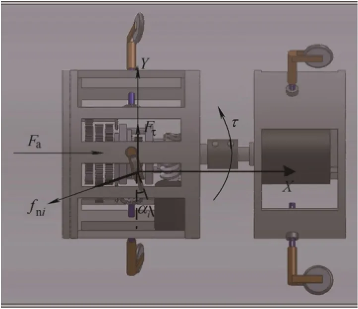
Fig. 5. Force relationship in the straight pipe
The counter-acting force of Fais the traction force of the robot. Therefore, the maximum traction force Fts,maxin the straight pipes can be calculated by
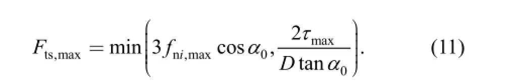
From Eq. (11), we can see that Ft,maxis invariable when fni,maxand τmaxare selected. However, for the proposed robot,we can adjust Ft,maxby changing0αof the adaptive linkage mechanism.
3.2 Traction computation in curved pipes
Fig. 6 shows the motion model in the curved pipes. The force relationship is expressed as
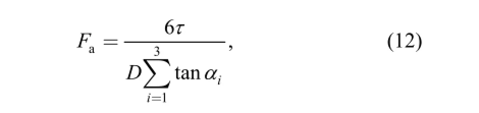
s.t.
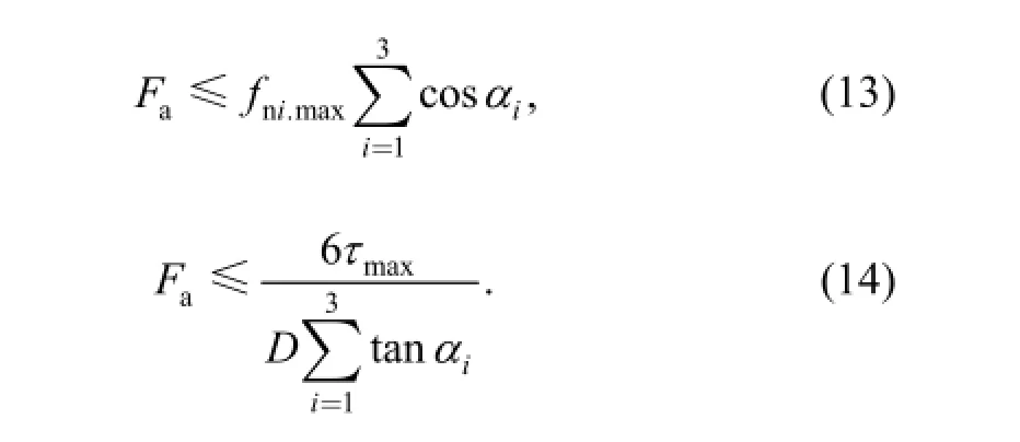
In the curved pipes, the maximum traction force Ftc,maxcan be calculated by
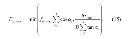
αichanges all along with the rotation of the robot. αican be obtained by the velocity relationship of the rollers.When the velocity of each roller fulfills the relations as Eq.(16), the robot will steer without motion interference:
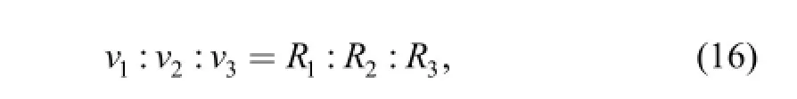
where viand Ridenote the velocity component and the steering radius of the ith roller, respectively. viand Rican be calculated by
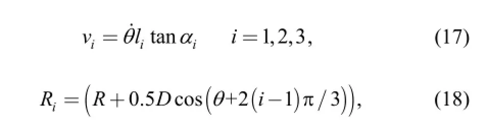
where li, αiandθ˙denote the length of each arm, the inclining angle of rollers and the rotation velocity of driving motor, respectively.
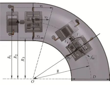
Fig. 6. Velocity and force relationship in curved pipes
Rewrite Eq. (7) as
From the equation set composed of Eqs. (15)-(19),Ftc,maxcan be calculated by a numerical method and the results are shown in Fig. 7.
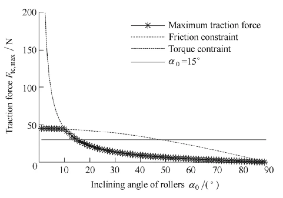
Fig. 7. Traction force comparison in the curved pipe
The results reveal that the maximum traction force can be adjusted by changing0αunder the friction constraint and torque constraint. The varied0αmakes the robot more flexible to the variable environment resistance than the fixed0α. It is easy to prove the same law in the straight pipe. And the maximum traction force in the curved pipes is almost the same as that in the straight pipe. This result presents that the proposed robot with the adaptive linkage mechanism avoids the motion interference in the steering motion. It is possible to control the output torque of motor by adjusting0αin variable resistance environment.
4 Control Method Based on Fuzzy Theory in Variable Resistance Environment
For the wide range of the variable resistance, the robot should provide enough traction capacity. Simultaneously,the output torque of the driving motor is required in a feasible region in consideration of safety and efficiency. Torque control method based on fuzzy theory is thus proposed here.
4.1 Control law and controller structure
The active adjustment of inclining angles of rollers for our proposed robot brings two advantages: improvement of traction capacity and withstanding larger environment resistance; more flexibility by both adjusting inclining angles and output torque of the driving motor while confronting a same resistance.
The output torque τ increases with the environment resistance and vice versa when0αis fixed. This way easily makes the drive motor work in a low efficiency region or beyond the allowed region. We can conclude from Eqs. (8)and (12) that output torque τ increases in proportion to0α when Fais invariable both in the straight and curved pipes. And the situation in the curved pipe is shown in Fig. 8. This control law allows the output torque to work in an expected region when the resistance is changed.
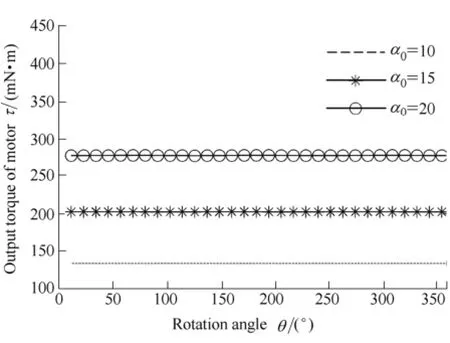
Fig. 8. Relation between τ and αiin curved pipes when Fais selected as 10 N.
When τ is very high,0αshould be decreased quickly in case that the motor is overloaded. However, when τ is low,0αshould be increased slowly in case that a suddenresistance results in motor overload. The expected control law is asymmetric. So far, the dynamics model of the screw drive in-pipe robot in the curved pipe has not been established. And the feedback information of sensors are just the rotational velocity and torque of motor. It is difficult to obtain a precise control method. The fuzzification and flexibility of the fuzzy theory in designing control rules are suitable for the control. Therefore, we adopt the fuzzy theory to establish the torque control method. The fuzzy controller can realize the real time control with low computational complexity.
The control structure is presented in Fig. 9. τminand τmaxdenote the lower limit and upper limit of the given feasible region. The given constant is a region instead of an accurate value because the real time adjusting of the inclining angles may result in the instability of the movement. The feasible region is selected based on the optimal working point. The motor efficiency arrives at the peak value when the output torque of the motor is one third of the rated torque[18]. Therefore, we choose the interval [0.3τe, 0.4τe] as the feasible region. This feasible region can also make the output torque less than the maximum torque τm.
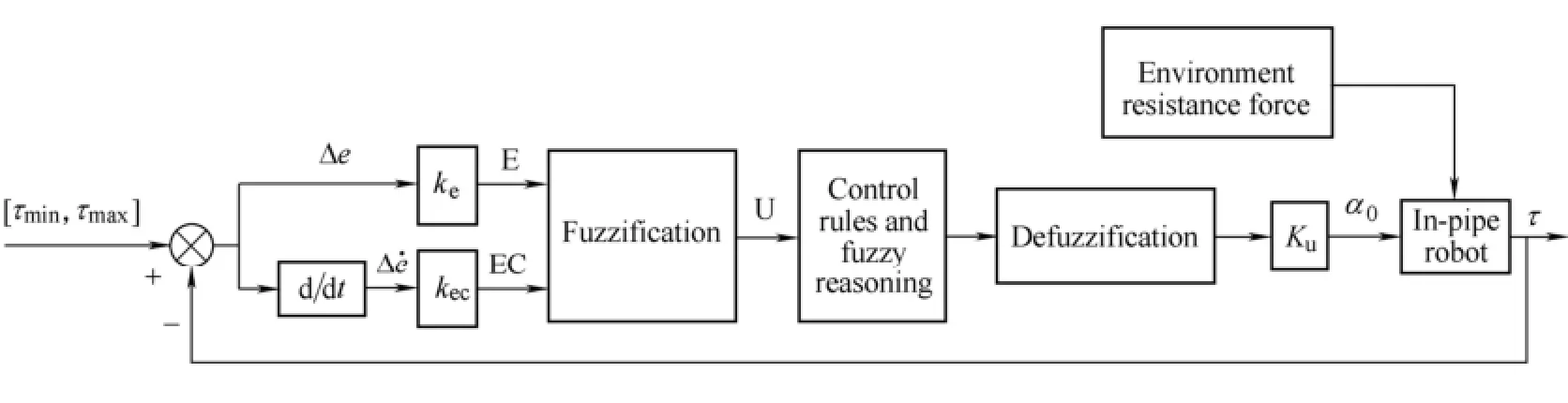
Fig. 9. Diagram of the fuzzy controller structure
The torque error is defined by
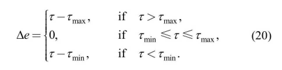
The error eΔ and the error rate eΔ˙ are introduced as the input variables of the fuzzy controller. The inclining angular velocity0α˙ that is the output variable of the fuzzy control is used to control the motor input of the adaptive linkage mechanism.
4.2 Fuzzification
The input variables eΔ and eΔ˙ are transformed into the universe by the quantization factors keand kec,respectively. The universe is set as {-6, -5, -4, -3, -2, -1,0, 1, 2, 3, 4, 5, 6}. Divide the universe into seven fuzzy subsets that are described as {NB, NM, NS, Z, PS, PM,PB}. Triangle membership function is adopted for the fuzzy subsets. The function curves are shown in Fig. 10.
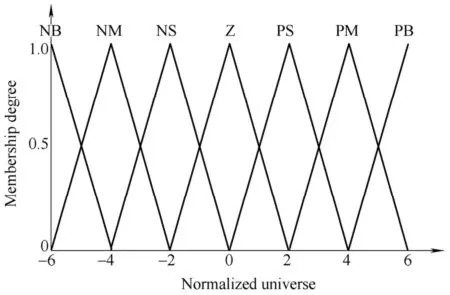
Fig. 10 Membership function curve
4.3 Fuzzy control rules
When erroreΔand the error rateeΔ˙are positive,0α should be decreased. Otherwise,0αshould be increased to compensate the negative error of the torque τ. The fuzzy control follow the below rules:
(1) When the error is big or positive, the control variable is chosen mainly considering the error elimination;
(2) When the error is small or negative, the control variable is chosen mainly considering the stability.
The fuzzy subsets of the output variable0α˙is chosen as the same as the input variables. Similarly, the triangle membership function is selected for the fuzzy subsets. BecauseeΔandeΔ˙are respectively defined as seven fuzzy subsets, there are forty nine fuzzy control rules. Table 1 presents the fuzzy control rules based on the control experience.
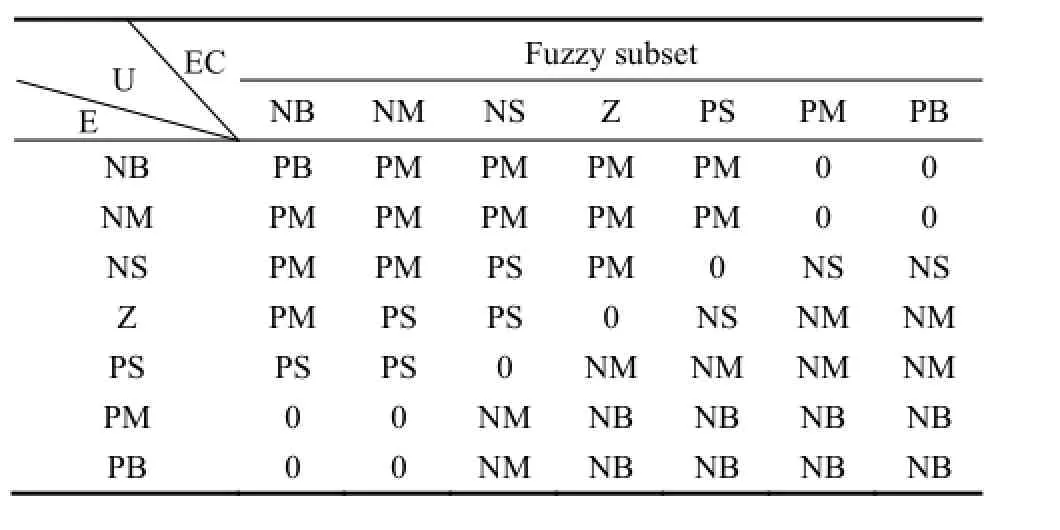
Table 1. Fuzzy control rules
The fuzzy controller adopts Mamdani reasoning algorithm[22]and barycenter method[23]defuzzification in consideration of its high precision. A fuzzy controller query table can be obtained through the fuzzy control rules, fuzzy reasoning and defuzzification method. In every controlperiod, the feedback error eΔandeΔ˙are transferred from sensors into the discrete universe. We can find out the output control variable in the fuzzy controller query table. By multiplying a scale factor k0,0α˙can be used to control the driving motor of the adaptive linkage mechanism.
5 Simulation Verification
5.1 Simulation platform
The verification tests are implemented in a simulation platform that is built in the Simulink and Adams softwares. As shown in Fig. 11, the robot model and the pipe model are established by the secondary development function in the Adams software. And the output torque τ is measured and input to the fuzzy controller system built in the Simulink software. The controller system provides controlled variable0α˙for the robot. The parameters of the robot are listed in Table 2.
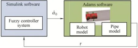
Fig. 11. Simulation platform
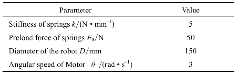
Table 2. Parameters of the robot
The quantization factor keand kecof the indirect fuzzy controller are selected as 0.3 and 0.06, respectively. And the scale factor k0is selected as 5. τeis equal to 600 mNm.
5.2 Control method verification
In the pipes, the variable environment resistance can be divided into two kinds of input signals. One can be regarded as the step signal that results from the barriers,while the other changes continuously, such as in a curved pipe positioned vertically.
5.2.1 Step response test
In order to test the step response performance, the robot is placed in a horizontal straight pipe and a preload resistance force f is acted on the robot at the time of 0 s as shown in Fig. 12. The preload resistance force f can be regarded as a step signal.
As shown in Fig. 13, the two green lines represent the upper limit and lower limit of the feasible region. The red dashed curve denotes the output torque with the proposed control method and the blue line denotes the output torque with fixed inclining angles. We can see that the output torque can be adjusted into the feasible region in the time of about 0.2 s.
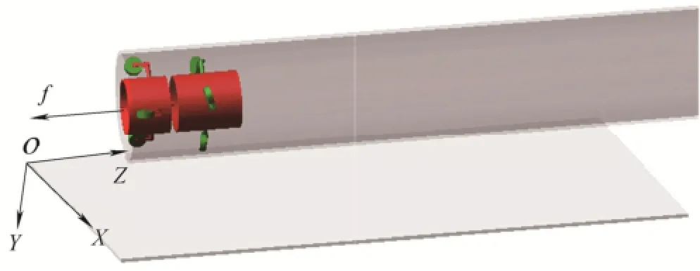
Fig. 12. Straight pipe structure diagram
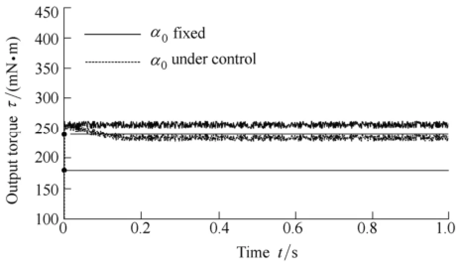
Fig. 13. Output torque comparison in step response test
Fig. 14 shows the curve of inclining angle0α that is adjusted by the fuzzy controller. Because the output torque is higher than the upper limit of feasible region, the inclining angle is decreased until the torque is in the feasible region.
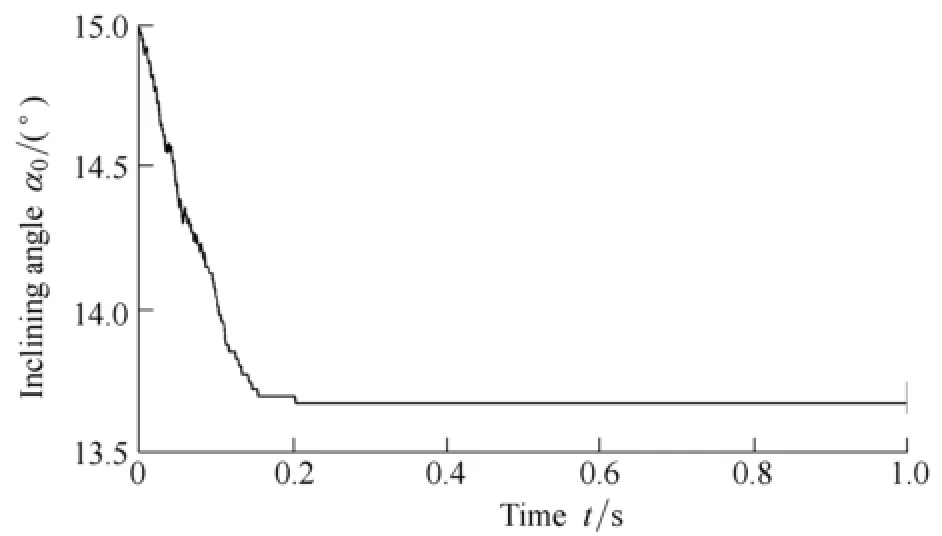
Fig. 14. Inclining angle0αin the step response test
From the result of the step response, we can conclude that the proposed control method is valid for the step disturbance.
5.2.2 Pipe environment test
Generally, the pipe environments in the engineering applications are complex and the resistance is variable. In order to fully verify the proposed method, we choose a pipe composed of the straight and curved pipes as shown in Fig. 15. The gravity is in the direction of Y-axis. In consideration of the gravity and spring elastic force, the resistance acted on the robot is varied.
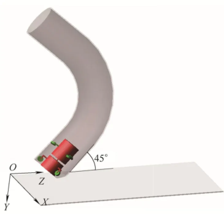
Fig. 15. Complex pipe structure diagram
In Fig. 16, the results show that the output torque in the blue solid curve is out of the feasible region in the most time, which means low working efficiency of the motor. If the proposed fuzzy controller is adopted, the output torque in the red dashed curve is limited in the feasible region. Fig. 17 shows the curve of the inclining angle. In the time of 3 s and 11 s, the inclining angle is changed sharply to adapt to the resistance resulted from the inner wall of the curved pipe. The curve of the inclining angular velocityiα˙is shown in Fig. 18. The results show that the output torque can be limited in the feasible region by the proposed method. And the robot can provide enough traction force for the resistance of the environment. The adaptive linkage mechanism and the torque control method improve the flexibility and adaptability of the in-pipe robot in both the straight pipe and the curved pipes.
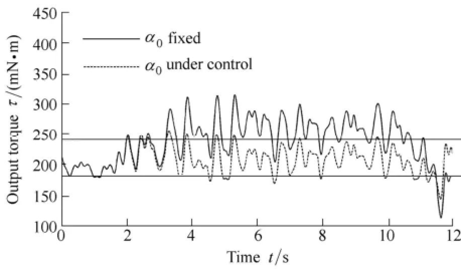
Fig. 16. Output torque comparison in the changeable pipe environment
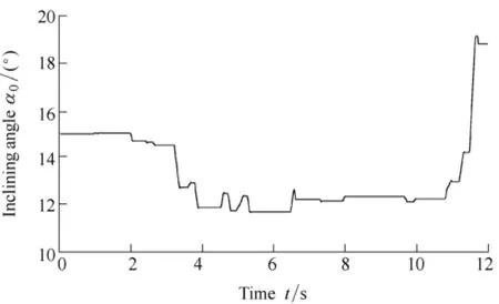
Fig. 17. Inclining angle0αin the changeable pipe environment
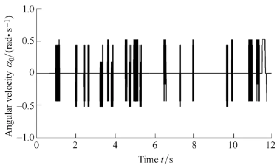
Fig. 18. Angular velocity0α˙in the changeable pipe environment
6 Conclusions
(1) A new screw drive in-pipe robot with the adaptive linkage mechanism is proposed, which can pass through the straight and varied curved pipes adaptively. The active adjustment of the inclining angles enhances the traction capacity and the adaptability to the wide range of environment resistance.
(2) A torque control method based on the fuzzy theory in the variable resistance environment is proposed. This method indirectly controls the output torque of the drive motor in a feasible region by changing the inclining angles.
(3) The dynamics simulation results show that the proposed method can make the motor of the robot work in the efficient and safe region in the variable resistance environments.
[1] LIU Yu, ZHAO Jing, LU Zhengyang, et al. Pose planning for the end-effector of robot in the welding of intersecting pipes[J]. Chinese Journal of Mechanical Engineering, 2011, 24(2): 264-270.
[2] HU Z, APPLETON E. Dynamic characteristics of a novel self-drive pipeline pig[J]. IEEE Transactions on Robotics, 2005, 21(5): 781-789.
[3] KIM H M, SUH Y S, CHOI T D, et al. An in-pipe robot with multi-axial differential gear mechanism[C]//IEEE/RSJ International Conference on Intelligent Robots and Systems(IROS), Tokyo, Japan,November 3-7, 2013: 252-257.
[4] PARK J J, MOON J W, KIM H, et al. Development of the untethered in-pipe inspection robot for natural gas pipelines[C]//IEEE International Conference on Ubiquitous Robots and Ambient Intelligence(URAI), Jeju, Korea, October 30-November 1, 2013: 55-58.
[5] LEE D, PARK J, HYUN G, et al. Novel mechanisms and simple locomotion strategies for an in-pipe robot that can inspect various pipe types[J]. Mechanism and Machine Theory, 2012, 56: 52-68.
[6] KAKOGAWA A, NISHIMURA T, MA S. Designing arm length of a screw drive in-pipe robot for climbing vertically positioned bent pipes[J]. Robotica, 2014, FirstView: 1-22.
[7] HIROSE S, OHNO H, MITSUI T, et al. Design of in-pipe inspection vehicles for Ф25, Ф50, Ф150 pipes[C]//IEEE International Conference on Robotics and Automation(ICRA),Detroit, USA, May 10-15, 1999: 2309-2314.
[8] LIU Qingyou, LI Yujia, REN Tao, et al. An active helical drive in-pipe robot[J]. Robot, 2014, 36(6): 711-718.
[9] KWON Y S, YI B J. Design and motion planning of a two-module collaborative indoor pipeline inspection robot[J]. IEEE Transactions on Robotics, 2012, 28(3): 681-696.
[10] QIAO Jinwei, SHANG Jianzhong, GOLDENBERG A. Development of inchworm in-pipe robot based on self-locking mechanism[J]. IEEE/ASME Transactions on Mechatronics, 2013, 18(2): 799-806.
[11] KISHI T, IKEUCHI M, NAKAMURA T. Development of a peristaltic crawling inspection robot for 1-inch gas pipes with continuous elbows[C]//IEEE/RSJ International Conference on Intelligent Robots and Systems(IROS), Tokyo, Japan, November 3-7,2013: 3297-3302.
[12] KUWADA A, ADOMI Y, SUZUMORI K, et al. Snake-like robot negotiating three-dimensional pipelines[C]//IEEE International Conference on Robotics and Biomimetics(ROBIO), Sanya, China,December 15-18, 2007: 989-994.
[13] ZAGLER A, PFEIFFER F. “MORITZ” a pipe crawler for tube junctions[C]//IEEE International Conference on Robotics and Automation(ICRA), Taipei, China, September 14-19, 2003: 2954-2959.
[14] ZHANG Yongshun, BAI Jian wei, CHI Minglu, et al. Optimal control of a universal rotating magnetic vector for petal-shaped capsule robot in curve environment[J]. Chinese Journal of Mechanical Engineering, 2014, 27(5): 880-889.
[15] IWASHINA S, HAYASHI I, IWATSUKI N, et al. Development of in-pipe operation micro robots[C]//International Symposium on Micro Machine and Human Science, Nagoya, Japan, October 2-4,1994: 41-45.
[16] LIU Qingyou, REN Tao, CHEN Yonghua. Characteristic analysis of a novel in-pipe driving robot[J]. Mechatronics, 2013, 23(4): 419-428.
[17] KAKOGAWA A, NISHIMURA T, MA Shugen. Development of a screw drive in-pipe robot for passing through bent and branch pipes[C]//International Symposium on Robotics(ISR), Seoul, Korea,October 24-26, 2013: 1-6.
[18] LI Te, MA Shugen, LI Bin, et al. Control strategies of energy optimization for an in-pipe robot with inclining-angle-adjustable screw rollers[J]. Journal of Mechanical Engineering, 2014, 50(17): 8-16.
[19] LI Te, MA Shugen, LI Bin, et al. Axiomatic design method to design a screw drive in-pipe robot passing through varied curved pipes[J]. Science China Technological Sciences, 2015, 58(1): 1-12.
[20] FATEH M M, AZARGOSHASB S. Discrete adaptive fuzzy control for asymptotic tracking of robotic manipulators[J]. Nonlinear Dynamics, 2014, 78: 2195-2204.
[21] AI-DABBAGH R D, KINSHEEL A, MEKHILEF M S, et al. System identification and control of robot manipulator based on fuzzy adaptive differential evolution algorithm[J]. Advances in Engineering Software, 2014, 78: 60-66.
[22] AYMERICH F X, SOBREVILLA P, MONTSENY E, et al. Detection of hyperintense regions on MR brain images using a mamdani type fuzzy rule-based system: Application to the detection of small multiple sclerosis lesions[C]//IEEE International Conference on Fuzzy Systems(FUZZ), Taipei, China, June 27-31,2011: 751-758.
[23] BROEKHOVEN E V, BAETS B D. A comparison of three methods for computing the center of gravity defuzzification[C]//IEEE International Conference on Fuzzy Systems(FUZZ), Budapest,Hungary, July 25-27, 2004: 1537-1542.
Biographical notes
LI Te, born in 1987, is currently a PhD candidate at State Key Laboratory of Robotics, Shenyang Institute of Automation,Chinese Academy of Sciences, China. He is also at University of Chinese Academy of Sciences, China. His research interests include intelligent robotics and robot control system.
E-mail: lite@sia.cn
MA Shugen, born in 1963, is currently a professor at Department of Robotics, Ritsumeikan University, Shiga-ken, Japan. He is also at State Key Laboratory of Robotics, Shenyang Institute of Automation, Chinese Academy of Sciences, China. His research interests include the design and control theory of new types of robots and biorobotics.
E-mail: shugen@se.ritsumei.ac.jp
LI Bin, born in 1963, is currently a professor at State Key Laboratory of Robotics, Shenyang Institute of Automation,Chinese Academy of Sciences, China. He received his master degree from China Medical University, Shenyang, China, in 1988. His current research interests include rescue robotics and biorobotics.
E-mail: libin@sia.cn
WANG Minghui, born in 1980, is currently an assistant professor at State Key Laboratory of Robotics, Shenyang Institute of Automation, Chinese Academy of Sciences, China. His current research interests include reconfigurable robots and modular robots.
Tel: +86-24-23970102; E-mail: mhwang@sia.cn
WANG Yuechao, born in 1960, is currently a professor at State Key Laboratory of Robotics, Shenyang Institute of Automation,Chinese Academy of Sciences, China. His current research interests include control theory of intelligent robotics.
E-mail: ycwang@sia.cn
10.3901/CJME.2015.0717.096, available online at www.springerlink.com; www.cjmenet.com; www.cjme.com.cn
* Corresponding author. E-mail: mhwang@sia.cn
Supported by National Natural Science Foundation of China(Grant No. 61273345)
© Chinese Mechanical Engineering Society and Springer-Verlag Berlin Heidelberg 2015
January 15, 2015; revised July 15, 2015; accepted July 17, 2015
杂志排行

Chinese Journal of Mechanical Engineering的其它文章
- Influence of Alignment Errors on Contact Pressure during Straight Bevel Gear Meshing Process
- Shared and Service-oriented CNC Machining System for Intelligent Manufacturing Process
- Material Removal Model Considering Influence of Curvature Radius in Bonnet Polishing Convex Surface
- Additive Manufacturing of Ceramic Structures by Laser Engineered Net Shaping
- Kinematics Analysis and Optimization of the Fast Shearing-extrusion Joining Mechanism for Solid-state Metal
- Springback Prediction and Optimization of Variable Stretch Force Trajectory in Three-dimensional Stretch Bending Process