Parametric Analysis of the End Face Engagement Worm Gear
2015-11-01DENGXingqiaoWANGJuelingWANGJingeCHENShouanandYANGJie
DENG Xingqiao, WANG Jueling*, WANG Jinge, CHEN Shouan, and YANG Jie
1 School of Mechanical Engineering and Automation, Xihua University, Chengdu 610039, China2 Department of Mechanical Engineering, Chengdu Industrial Vocational Technical College, Chengdu 610218,China3 School of Manufacturing Science and Engineering, Sichuan University, Chengdu 610065, China
Parametric Analysis of the End Face Engagement Worm Gear
DENG Xingqiao1, WANG Jueling2,*, WANG Jinge1, CHEN Shouan1, and YANG Jie3
1 School of Mechanical Engineering and Automation, Xihua University, Chengdu 610039, China
2 Department of Mechanical Engineering, Chengdu Industrial Vocational Technical College, Chengdu 610218,China
3 School of Manufacturing Science and Engineering, Sichuan University, Chengdu 610065, China
A novel specific type of worm drive, so-called end face engagement worm gear(EFEWD), is originally presented to minimize or overcome the gear backlash. Different factors, including the three different types, contact curves, tooth profile, lubrication angle and the induced normal curvature are taken into account to investigate the meshing characteristics and create the profile of a novel specific type of worm drive through mathematical models and theoretical analysis. The tooth of the worm wheel is very specific with the sine-shaped tooth which is located at the alveolus of the worm and the tooth profile of a worm is generated by the meshing movement of the worm wheel with the sine-shaped tooth, but just the end face of the worm(with three different typical meshing types) is adapted to meshing, and therefore an extraordinary manufacturing methods is used to generate the profile of the end face engagement worm. The research results indicates that the bearing contacts of the generated conjugate hourglass worm gear set are in line contacts, with certain advantages of no-backlash, high precision and high operating efficiency over other gears and gear systems besides the end face engagement worm gear drive may improve bearing contact, reduce the level of transmission errors and lessen the sensitivity to errors of alignment. Also, the end face engagement worm can be easily made with superior meshing and lubrication performance compared with the conventional techniques. In particular, the meshing and lubrication performance of the end face engagement worm gear by using the end face to meshing can be increased over 10% and 7%, respectively. This investigate is expect to provide a new insight on the design of the future no-backlash worm drive for industry.
worm drive, end face engagement worm gear, meshing characteristics, anti-backlash.
1 Introduction*
The development of advanced mechanism transmission is important in order to eliminate backlash and improve the precision under large loading conditions. Backlash phenomenon is characterized by the existence of dead zone area, which is caused by the gap between input and output system positions. Backlash is necessary in the traditional gearing sets[1]. For example, backlash provides the space for the lubricants and can reduce the risk to be blocked off between a pair of adjacent gear teeth when distorted and inflated due to the force and friction during operation[2]. However, the dead zone area may adversely affect the system performance during the operation in a closed loop process, such as the track precision of a radar system, and the stability of industrial robots. In addition, the anti-backlash with high precision is needed in some mechanism transmission, e.g. numerical control machines system[3].
Backlash is one of the most significant nonlinearities that limit the performance of the mechanical manipulators. Considerable works have been conducted to study the backlash phenomenon or eliminate the backlash with novel structure or mechanisms. CHEN, et, al[4], created a valid method to calculate the backlash based on the fractal theory,the investigations can be utilized to improve gear dynamics characters through guiding gear surface and design and manufacture in the future. MENJAK, et al[5], presented an adjustable gear mechanism including a convoluted spring positioned between an external spline of a gear or shaft and an internal spline for minimizing or overcoming the gear backlash. LUMPKIN, et al[6], developed a planetary gear device to minimize or eliminate the backlash within the planetary gear system, the planetary gear system includes a planetary gear assembly having a first planetary gear and second planetary gear rotatable relative to the first planetary gear, and a torqueing mechanism. ASK, et al[7],proposed an apparatus to decrease gear train backlash. This apparatus includes at least two interacting gear rims that rotate in relation to one another. In addition, MERZOUKI,et al[8], developed a method using fault detection and isolation model for the backlash phenomenon, etc. Also,CHEN, et al[9], established a novel worm drive consisting of a planar internal gear and a crown to meet the increasing requirements of minimum backlash in the modern industrial and aerospace technology.
Although the abovementioned apparatus has many advantages, they are either structurally complex or too many transmission components so that it is difficult to adapt to the gearing of the servo system under high precision or big loading conditions. Therefore, it is necessary to develop a new anti-backlash worm with extreme precision.
In this paper, a new kind of anti-backlash end face engagement worm gear(EFEWG) is proposed firstly on the basis of the considerable study works for WANG and DENG[10-12]. As aforementioned, the tooth of the worm is generated by the meshing movement of the worm wheel,and the tooth of worm wheel is specifically with the sine-shaped tooth with high horsepower-to-weight ratio. First of all, the mathematical model of the end face engagement worm gear set is developed according to the theory of worm gearing. Then, the bearing contacts of the generated conjugate hourglass worm gear set are discussed. Three-dimensional solid model of the end face engagement worm and worm wheel is generated according to the mathematical model of worm gear sets. In addition, the effects of different factors on the transmission performance are also investigated, such as three types, contact curves,tooth profile, lubrication angle and the induced normal curvature, tooth profile of anti-backlash end face engagement worm. It is found that the end face engagement worm gear set can guarantee the worm gear set to automatically eliminate the backlash in the worm drive. This design also has numerous other benefits, including a high horsepower-to-weight ratio, a higher contact ratio,compactness, and high lubrication property. The developed computer-aided simulation tool can contribute to the design and contact analysis of the different kind of anti-backlash sine-edged enveloping hourglass worm sets.
The anti-backlash end face engagement worm gear(EFEWG) is a new type of a worm gear train which consists of three parts, as shown in Fig. 1, the hollow left worm as part #6, the right hollow worm as part #8 and the worm wheel part #7. Also, Part#1 is nut, Part#2 is gasket,Part#3 is the Axial positioning device, Part#4 is the snap spring, Part #5 is wedge adjusting mechanism, Part#7 is worm wheel, Part#9 is the connect axis.
The left hollow worm and right hollow worm are separated along the operation line. The worm moves along the direction of rotation of the worm gear, and the hollow worm moves in the opposite direction. During the forward and backward operation, either left worm or right worm contacts with the worm wheel to give the force for transmission, which eliminates the backlash phenomena. The left worm and right worm are connected with a spring,which can adjust the positions for each worm over a wide range in order to keep close contacts between the tooth profiles for both worms and the sine-shaped teeth. The sine-shaped teeth serve as the media to link the shank worm and the hollow worm. Each of the sine-shaped teeth is located in the alveolus of the worm, as shown in Fig. 2. The left profile of the sine-shaped tooth transmits in the positive movement and the right profile in the negative movement. By doing so, three types of EFEWG are derived from Fig. 2 as shown in Fig. 3. The worm consists of Part #6 and Part #8.
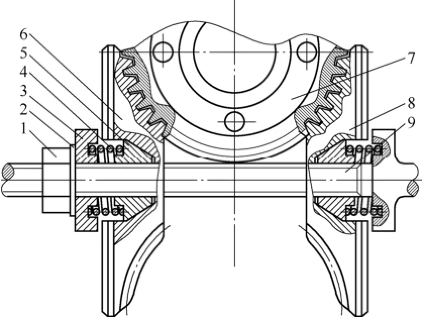
Fig. 1. Sketch of the worm wheel for the anti-backlash end face engagement worm gear(AEFEWG)1. Nut; 2. gasket; 3. Axial positioning device; 4. Snap spring;5. Wedge adjusting mechanism; 6. Left worm; 7. Worm wheel;8. Right worm; 9. Connect axis.
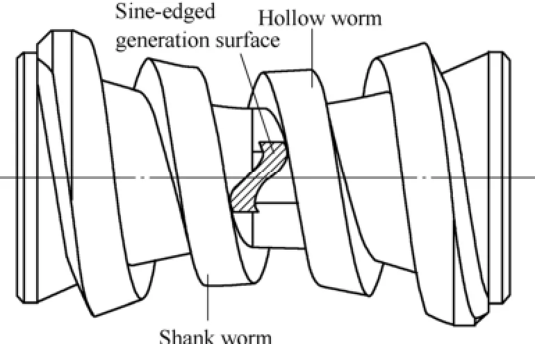
Fig. 2. Sketch of the worm wheel showing that the sineshaped tooth is located at the alveolus of the worm
2 Mathematical Model
2.1 Meshing model
As shown in Fig. 4, the fixed coordinate system S1(i1, j1,k1) is connected to the worm, whereas the moving coordinate system S1′(i1′, j1′, k1′) is attached to the worm and rotates about the axis k1′at the centre of the worm by angular speed ω1. The fixed coordinate system S1represents the original location of S1′. Angle φ1represents the rotational angle of the worm. The transformation from S1′to S1can be described as M11′.
Similarly, the fixed coordinate system S2(i2, j2, k2) is connected to the worm wheel. Correspondingly, a moving coordinate system S2′(i2′, j2′, k2′) is attached to the worm wheel and rotates about the axis k2′in the centre of the worm wheel by angular speed ω2.By doing so, the gearratio i21=1/i12=ω2/ω1, the fixed coordinate system S2represents the original location of S2′. Angle φ2represents the rotational angle of the worm wheel. The transformation from S2to S2′can be described as M2′2. The coordinate systems S0(i0, j0, k0) is rigidly connected to the gear in the center of the top surface of sine-shaped tooth, the revolving axis of the sine-shaped tooth is along the radial direction of the gear and the axis k0is perpendicular to the axis k2,assuming the coordinate of O0represented in coordinate system is (a2, b2, c2)[1-2].
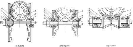
Fig. 3. Three different types for the EFEWG
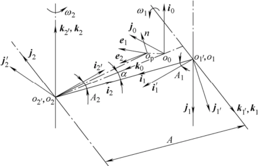
Fig. 4. Description of the coordinate systemsS0(i0, j0, k0)—Fixed coordinate system attached rigidly to the center of roller topS1(i1, j1, k1)—Fixed coordinate system on the wormS2(i2, j2, k2)—Fixed coordinate system on the worm wheelS1′(i1′, j1′, k1′)—Movable coordinate system attached to the wormS2′(i2′, j2′, k2′)—Movable coordinate system attached to the worm wheel
The transformation from S0to S2′can be described as M2′0. The moving coordinate system[13-18]Sp(e1, e2, n) is included attached to the contact point of Op. The transformation from Spto S0is presented as M0p.
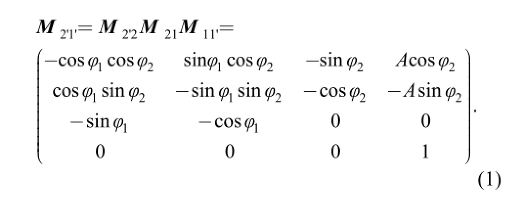
The transformation of coordinates from the fixed coordinated system S1to S2is given as M21. By combing these transformation matrixes, the transformation from the moving coordinate system S1′(rigidly connected to the worm) to the moving coordinate system S2′(rigidly connected to the worm wheel) is obtained as
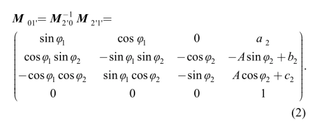
The transformation from the moving coordinate system S1′to the fixed coordinate system S0is obtained as
In order to develop the mathematical model of the sine-shaped meshing of the AEFEWG, the fixed coordinate system S0and the moving coordinate system Spare applied to the meshing surface for the worm wheel, as illustrated in Fig. 5, where u and θ is the parameters of the sine-shaped tooth for the worm wheel.
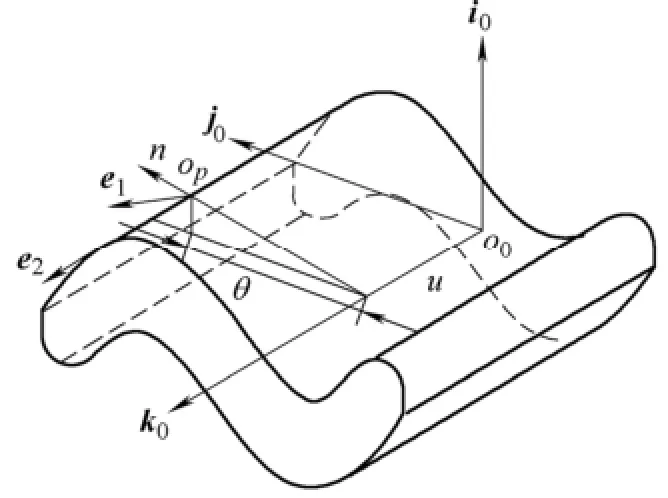
Fig. 5. Coordinate system of meshing a surface for the worm wheel
The generating surface of the sine-shaped tooth is obtained in the coordinate system S0asWhere x0=c2+sinθ, y0=Rθ, and z0=u, and R is the coefficient.

In Fig. 4, the moving coordinate system Sp(e1, e2, n) is attached to the contact point of Opand the fixed coordinate system S0(i0, j0, k0) is rigidly connected to the gear in the center of sine-edged top as shown in Fig. 3. The transformation from the fixed coordinate system S0to the rotatable coordinate system S2′can be obtained as
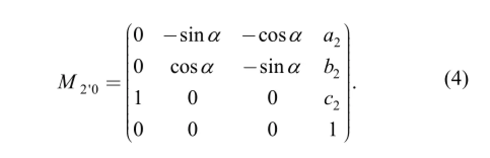
Where α is the geometry angle as shown in Fig. 3. Thus, the relationship between this sine-shaped coordinate system S1′and the worm wheel coordinate system S2′is given as
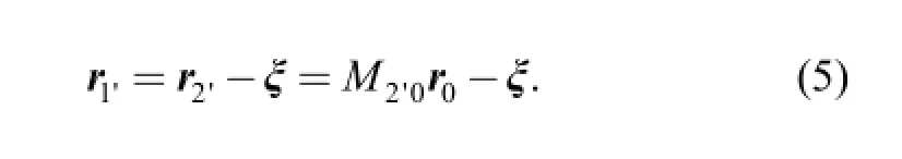
Where r1′represents the generating surface(enveloping)described in the moving coordinate system S1′, and r2′represents the position vectors of the contact point Opin the moving coordinate system S2′.
Based on the differential geometry theory[19-25], the radii vector relationship between the original point of coordinate system and the contact point is illustrated as Fig. 6.
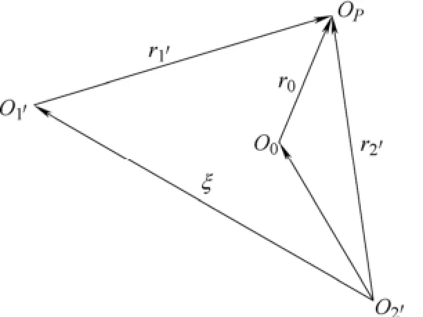
Fig. 6. Relationship between radii vectors
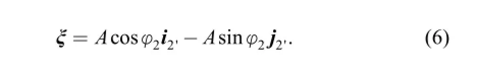
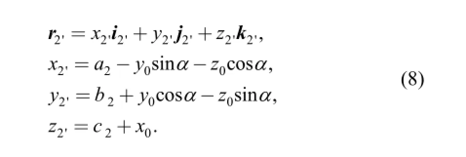
The centre distance vector between the new antibacklash end face engagement worm gear and the worm wheel in the rotatable coordinate system S2′can be described as
Further, r0indicates the generating(enveloping) surface described in the moveable coordinate system S0and can be described as
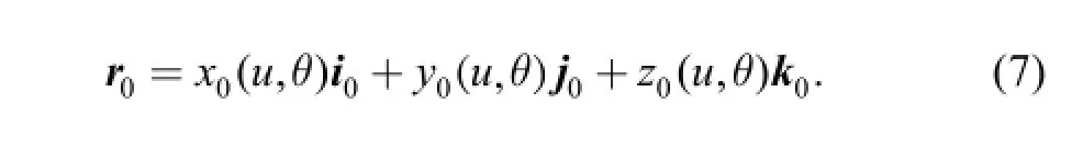
Where u and θ represent the meshing parameters on the generating surface. Through the coordinate transformation in Eq. (4), the generating surface of the sine-edged in the rotatable coordinate system S2′can be obtained as
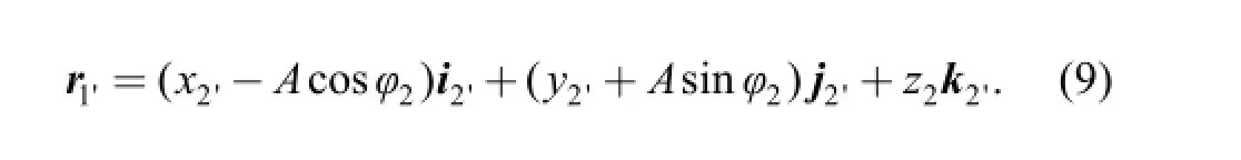
Applying Eqs. (1), (4), (5), (7), (8), the generating surface of the sine-shaped tooth in the coordinate system S1′can be described in the sine-edged coordinate system S2′as
Based on the theory of gear meshing, the meshing equation gives the necessary and sufficient condition of existences of the new anti-backlash end face engagement worm gear profile and can be obtained as
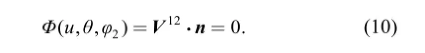
Where V12is the relative velocity vector of the worm with respect to the worm wheel on the contact point, and n is the unit normal vector of the worm tooth surface with respect to the conjugate contact point in axes n in the AEFEWG moveable coordinate system S0. The V12can be defined by the following equation:
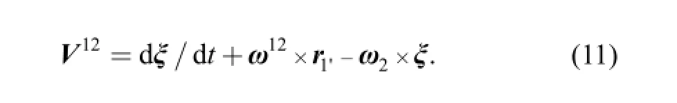
Where dξ/dt=0, ω12is the relative angular velocity vector of the worm with respect to the worm wheel and can be obtained as
The relative angular velocity vector of the worm with respect to the worm wheel in the coordinate Spcan be obtained as
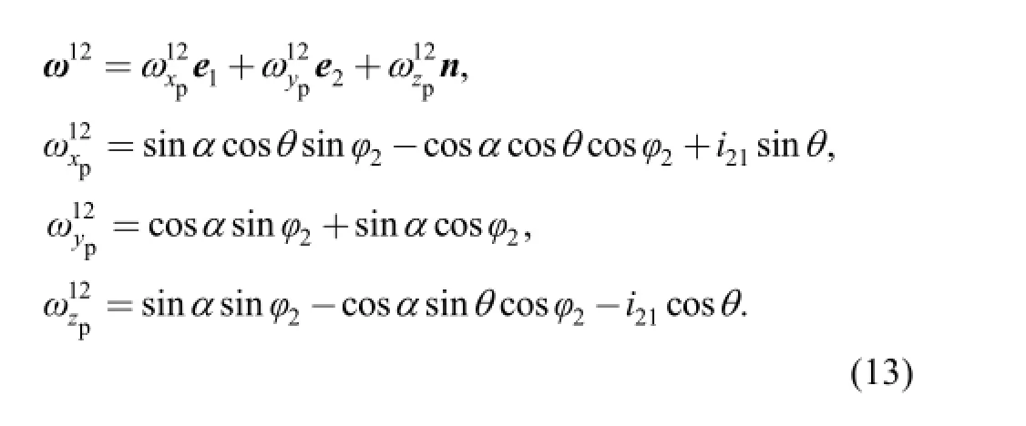
Applying Eqs. (7)-(9), (11)-(13), the relative velocity of the conjugate contact point Opin the moving coordinate system spcan be obtained as
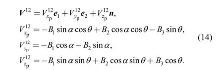
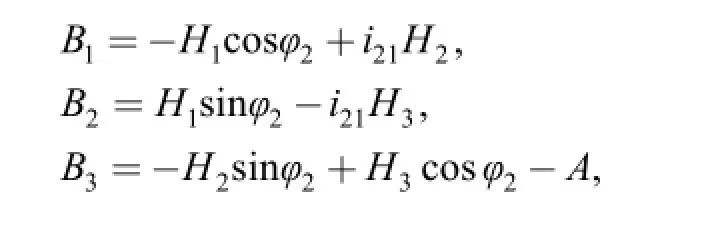
in which
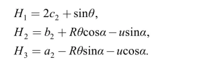
Thus, the meshing function for the sine-edged meshing can be described as
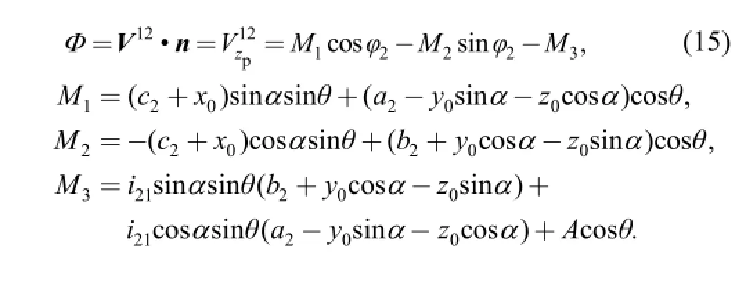
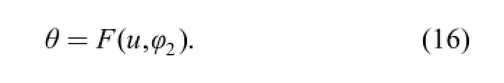
Applying Eq. (15), the relationship between the meshing parameter and θ is given as
Taking the derivation of the meshing functions in Eq. (15)with respect to mesh parameters u, θ and time t, it follows that
2.2 Meshing performance
2.2.1 Contact curve
The contact curve identifies the instant contact between a meshing sine curvature and the tooth profile of the end face engagement worm. According to Eqs. (7) and (16), the contact curve on the generating surface between the sine-edged and the worm can be given as
The contact curve on the generating surface can be transformed to the AEFEWG moveable coordinate frame. According to the theory of gear meshing, a large number of contact curves on this frame generate a tooth profile of the new worm as the following equation by integrating Eqs. (2),(4), (16) and (18):
2.2.2 Induced normal curvature and the lubrication angle
The induced normal curvature is the relative normal curvature between the two meshing surfaces, which can be used in various performance applications, such as stress analysis, tooth contact analysis, tooth profile machining and so on. The induced normal curvature of meshing between the new worm and the worm wheel is described as
The lubrication angle is the angular separation between the contact-line and the relative velocity, which can be utilized in the evaluation of the lubricant properties. The lubrication angle can be described as
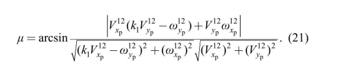
Based on the theory of gear meshing[26-33], the lubrication properties can be improved while the lubrication angle is closer to 90°; and the meshing has better performance as the induced normal curvature becomes smaller.
3 Meshing Performance Analysis
3.1 Contact curves
The contact curve on the generating surface is determined by Eq. (18). By substituting Eqs. (7), (16) into Eq. (18) with the parameters as shown in Table 1, the tooth surface of the end face engagement worm is constructed by the contact curve, as shown in Fig. 7. Fig. 7 shows the contact curve of the generating surface of sine-edged for the angle φ2which represents the rotational angle of the worm wheel is from 0° to 360°. In doing so, the rotational angle of the worm wheel φ2is from 20° to 35°,then the contact curve of the generating surface of worm shows as Fig. 8(a), also, the rotational angle of the worm wheel φ2is from 12° to 26°, then the contact curve of the generating surface of worm shows as Fig. 8(b). However, as the rotational angle of the worm wheel φ2is close to from 0° to 8°,then the contact curve of the generating surface of worm which is the normal structure for hourglass worm as shown Fig. 8(c).
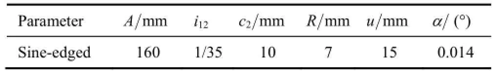
Table 1. Parameters for the worm
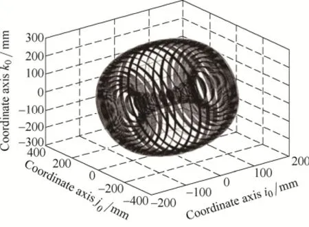
Fig. 7. Contact curve on the tooth-surface of whole worm
Fig. 8. Contact curve on the tooth-surface of worm
As shown in Fig. 7 or Fig. 8, the contact curve of worm is a straight line, which indicates that the EFEWG has the high contact ratio and the bearing contacts of the generated conjugate hourglass worm gear set are in line contacts.
Similarly, by substituting Eqs. (1), (7), (9), (14), (16) into Eq. (19) with the parameters as shown in Table 1, the tooth profile of the EFEWG generated by the meshing movement of the sine-edged can be obtained. Fig. 8 present the three dimensional solid models, respectively. Similarly, the rotational angle of the worm wheel φ2is from 20° to 35°,then three dimensional solid models shows as Fig. 8(a),also, the rotational angle of the worm wheel φ2is from 12° to 26°, then the three dimensional solid models shows as Fig. 8(b). However, as the rotational angle of the worm wheel φ2is close to from 0° to 8°,then the three dimensional solid models which are the normal structure for hourglass worm as shown Fig. 8(c).
It can be seen that the tooth sockets of end face engagement worm gear is very special. i.e. Shapes for the worm tooth are concave as shown Fig. 9(a), meanwhile, the shapes for the worm tooth are convex.
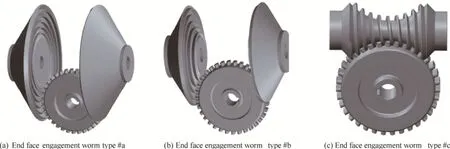
Fig. 9. Three dimensional model
3.2 Induced normal curvature and lubrication angle
Based on the meshing theory, the induced normal curvature and the lubrication angle are the key meshing parameters which are usually used in the stress, tooth contact analysis, tooth profile machining and can be used to estimate the meshing and lubricant properties.In doing so,the induced normal curvature and are determined by Eqs.(20) and (21), respectively. By substituting Eqs. (13), (14) ,(19) into Eqs. (20) and (21) with meshing parameters givenabove mentioned, the induced normal curvature and lubrication angle for the meshing sine-edged in the shape of sine shape can be obtained. The variation of the curvature and the lubrication angle with respect to the sine shapes are illustrated in Fig.10. It shows that the value of induced normal curvature for sine-edged meshing decrease with the tooth pitch angles α and radius of sine curvature R while increases with the setover c2, approximately 0.166 5 mm-1and slightly changes with different EFEWG tooth pitch angles α , radius of sine curvature R and the setover c2. Fig. 11 shows that he lubrication angle for the sine-edged decrease with tooth pitch angle α is over 84.5°, the lubrication angle for the sine-edged increase with the setover c2is over 85°., and the lubrication angle for the sine-edged increase with radius of sine curvature R is over 84.5°.
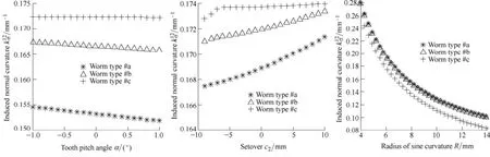
Fig. 10 Induced normal curvature values varying with α, β and R
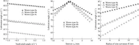
Fig. 11 Lubrication μ values varying with α, β and R
According to the meshing theory, the lubrication angle is close to the 90°,then the worm gear lubrication will be better, while the smaller the induced normal curvature ,then the meshing characteristic of the worm gear will be better. As shown in the Fig. 10 and Fig. 11, the descending order of induced normal curvature and the lubrication in the three designs is the inside engaged worm, followed by the end face engagement worm and then followed by the End face engagement worm divided from the throat of the worm.
4 Tooth Profile Machining
The complex tooth profile of the new anti-backlash sine-edged hourglass worm is generated by the meshing movement of the meshing sine-edged. Based on the relative movement between the worm and the worm wheel, the Mazak Integrex 200IV which is the leader in the manufacturer of advanced technology solutions including Multi-Tasking, 5-axis, milling, turning, CNC Controls and automation shown as Fig. 12 is used to manufacture the worm and worm wheel since it is very difficult to manufacture the tooth profile for both the worm and the worm wheel by using the normal hob machine. Fig. 13 illustrates the schematic of a manufacturing process. The Fig. 13(a) shows the worm manufacturing process followed by the Fig. 13(b) showing the worm wheel manufacturing process. During the manufacturing process, as shown in Fig. 13, the worm work piece is mounted on the shaft of the hob and rotates with the shaft. The fly-blade is fixed at a working-table and rotates with the working-table, and then the objected tooth profile for the worm and worm wheel are milled by the Mazak Integrex 200IV machine using CNC-program. Finally, the tooth profile of the new anti-backlash sine-edged hourglass worm is machined by the combination movement of the work piece and thefly-blade. Fig. 4 shows the milling process of the tooth profile of the new anti-backlash sine-edged enveloping hourglass worm. The grinder is drove by a high speed motor and the movements is the same like the manufacturing process.
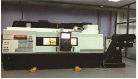
Fig. 12 Mazak Integrex 200IV
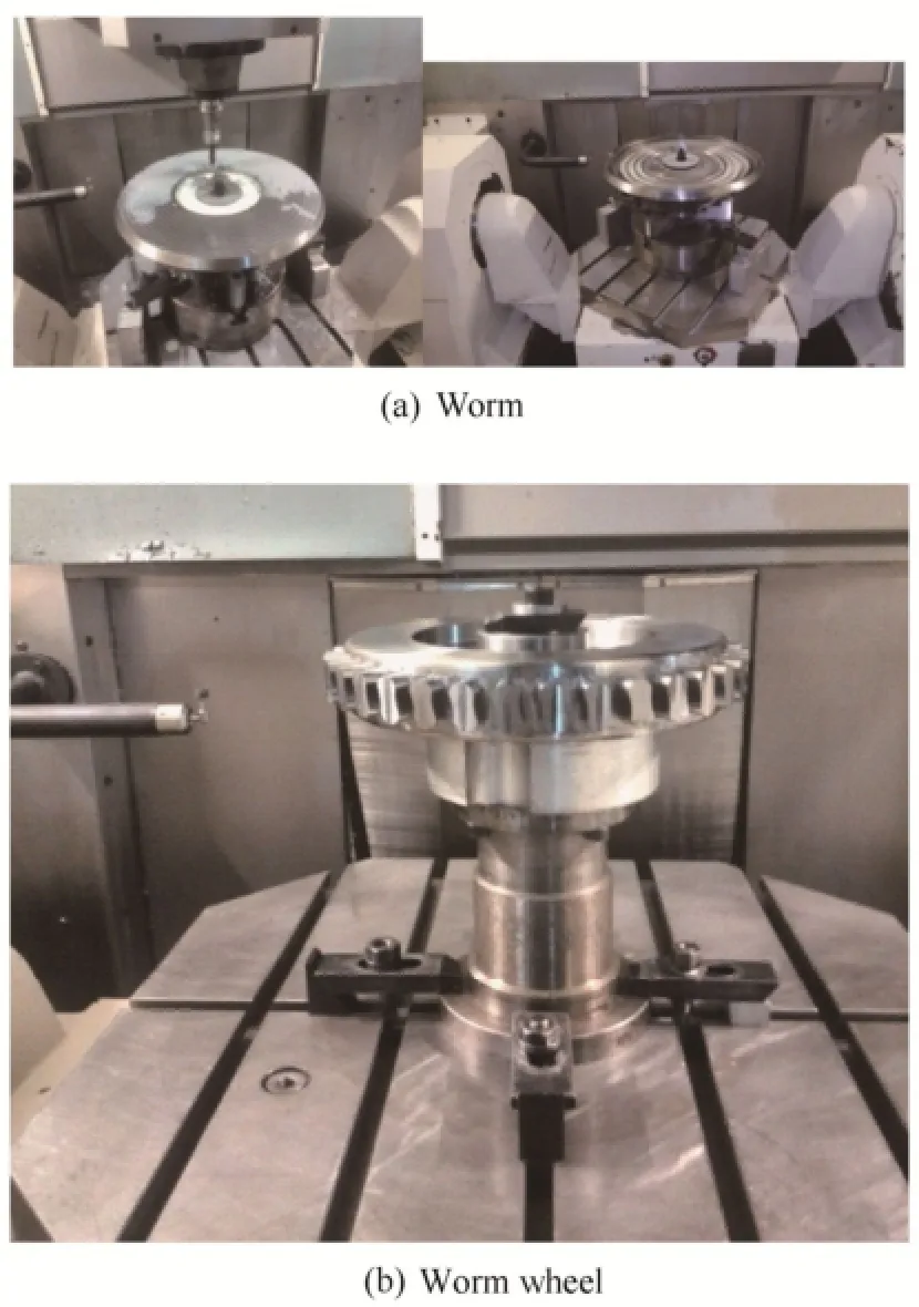
Fig. 13 Schematic of tooth profile manufacturing process
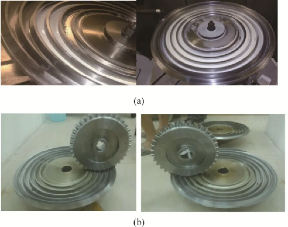
Fig. 14 Worm and the worm wheel
After the manufacturing, we have check the meshing between the worm and worm wheel, the experiment shows that the worm is very well to drive the worm wheel and the meshing are also very good. Fig. 14 shows the meshing for the worm and the worm wheel.
5 Conclusions
(1) A new kind of worm drive named end face engagement worm gear which include three different typical types is firstly proposed that includes two interacting worm that rotate in relation to one another. The novel apparatus can be used to reducing or eliminate the backlash in transmission system.
(2) The contact curves and three dimensional solid models of the EFEWG are also developed firstly. Correspondingly, the line contacts indicates the EFEWG offering certain advantages over other gears and gear systems such as high load capacity, high precision, and high operating efficiencies on the basis of the meshing theory analysis.
(3) The lubrication angle and the induced normal curvature are also discussed. The results indicated that the new kind of EFEWG with type #a has the best meshing performance and lubrication properties among the three typical, followed by the end face engagement worm with type #b and then followed by the End face engagement worm the end face engagement worm with type #c.
(4) The machine Mazak Integrex 200IV and a special CNC-program is carried out to manufacture the tooth profile for the face engagement worm and worm wheel. The results concluded that end face engagement worm and worm wheel has the good manufacturability. Also, the experiment indicates that the end face engagement worm and worm wheel mesh well hence it proves the mathematical model for the EFEWG is correctly.
[1] WANG Jinge, ZHANG Junfu, DENG Xingqiao et al. Parameter optimization of the anti-backlash double-roller enveloping hourglass worm gearing[J]. Journal of Mechanical Engineering,2010, 46(21): 6-12. (in Chinese)
[2] DENG Xingqiao, WANG Jinge, HORSTEMEYER M F, et al. Parametric study of meshing characteristics with respect to different meshing rollers of the anti-backlash double-roller enveloping worm gear[J]. Journal of Mechanical Design, 2012, 134(8): (081004-1)-(081004-12).
[3] DENG Xingqiao, WANG Jinge, ZHANG Junfu. The real tooth surface theory study of the non-backlash double-roller enveloping hourglass worm[J]. Journal of Southwest Jiaotong University, 2010,45(2): 222-226. ( in Chinese)
[4] CHEN Yonghong, ZHANG Guanghui, CHEN Bingkui, et, al. A novel enveloping worm pair via employing the conjugating planar internal gear as counterpart[J]. Mechanism and Machine Theory. 2013, 67(2): 17-31.
[5] MENJAK R, MENJAK D. Gear backlash elimination and justable gear backlash mechanism: USA, 6997076[P]. B2. 2003-2-10. http://www.google.com.ar/patents/US20040154422.
[6] LUMPKIN T, WOLF T. Methods and apparatus for minimizing backlash in a planetary mechanism: USA, 7121973[P]. 2004-5-5. http://www.google.com.ar/patents/US7121973.
[7] ASK K, HOJKROGH E N, HAKANSSON N O. Apparatus for reducing gear train backlash: USA, 7086302[P]. 2006-8-8. https://www.google.com/patents/US7086302.
[8] MERZOUKI R, MEDJAHER K, DJEZIRI M A, et al. Backlash fault detection in mechatronic system[J]. Mechatronic, 2007, 17(6): 299- 310.
[9] CHEN Qi, MA Yunbo, HUANG Shouwu, et al. Research on gears' dynamic performance influenced by gear backlash based on fractal theory[J]. Applied Surface Science, 2014, 313(1): 325-332.
[10] HONG Lei, WANG Jinge, ZHANG Junfu, et al. Meshing analysis of non-backlash double roller enveloping hourglass worm gearing[J]. Journal of Xihua University, 2008, 27(3): 18-23. (in Chinese)
[11] DENG Xingqiao, WANG Jinge, ZHANG Junfu. Optimization design of the non-backlash double roller enveloping hourglass worm's parameters based on genetic algorithm[J]. Journal of Sichuan University(Engineering Science Edition), 2010, 42(2): 250-254. (in Chinese)
[12] DENG Xingiqao, XIANG Zhongfan, WANG Jinge. Research on the tooth profile and contact curve of the non-backlash double-roller enveloping hourglass worm with errors[J]. Journal of Xi'an University, 2011, 45(2): 111-120. (in Chinese)
[13] BAHK C J, PARKER R G. Analytical investigation of tooth profile modification effects on planetary gear dynamics[J]. Mechanism and Machine Theory, 2013, 70(8): 298-319.
[14] ERITENEL T, PARKER R G. An investigation of tooth mesh nonlinearity and partial contact loss in gear pairs using a lumpedparameter model[J]. Mechanism and Machine Theory, 2012, 56(6): 28-51.
[15] FUJISAWA Y, KOMORI M. Surface finishing method for tooth flank of heat-treated surface-hardened small gears using a gear-shaped tool composed of alumina-fiber-reinforced plastic[J]. Precision Engineering, 2015, 39: 234-42. http://dx.doi.org/10.1016/ j.precisioneng.2014.10.003.
[16] GOLABI S, FESHARAKI J, YAZDIPOOR M. Gear train optimization based on minimum volume/weight design[J]. Mechanism and Machine Theory, 2014, 73(12): 197-217
[17] SIMON V. Influence of tooth errors and misalignments on tooth contact in spiral bevel gears[J]. Mechanism and Machine Theory,2008, 43(10): 1253-1267.
[18] LIN W S, SHIH Y P, LEE J J. Design of a two-stage cycloidal gear reducer with tooth modifications[J]. Mechanism and Machine Theory, 2014, 79(5): 184-97.
[19] CAO Xuemei, FANG Zongde, ZHANG Jinliang, et al. Functionoriented active tooth surface design of spiral bevel gears[J]. Chinese Journal of Mechanical Engineering, 2007, 43(8): 155-158.
[20] SUN Yuehai, LU Huawu, WANG Shuren. Profile of grinding wheel for grinding TI worm[J]. Chinese Journal of Mechanical Engineering, 2008, 44(2): 170-174.
[21] SUN Yuehai, DUAN Luqian, WANG Shuren, et al. Contact performance analysis of double enveloping worm gearing based on contact lines[J]. Chinese Journal of Mechanical Engineering, 2005,41(6): 44-49.
[22] LI S. Design and strength analysis methods of the trochoidal gear reducers[J]. Mechanism and Machine Theory, 2014, 81(7): 140-154.
[23] LITVIN F, FUENTES A, HAYASAKA K. Design, manufacture,stress analysis, and experimental tests of low-noise high endurance spiral bevel gears[J]. Mechanism and Machine Theory, 2006, 41(1): 83-118.
[24] TUNALIOĞLU M Ş, TUÇ B. Theoretical and experimental investigation of wear in internal gears[J]. Wear, 2014, 309(1): 208-215.
[25] SHI Zhaoyao, KANG Yan, LIN Jiachun. Comprehensive dynamics model and dynamic response analysis of a spur gear pair based on gear pair integrated error[J]. Journal of Mechanical Engineering. 2010, 46(17): 55-61.
[26] BAHRAMI GHAHNAVIEH A, AKBARZADEH S,MOSADDEGH P A. Numerical study on the performance of straight bevel gears operating under mixed lubrication regime[J]. Mechanism and Machine Theory, 2014, 75(1): 27-40.
[27] VILMOS V S. Influence of tooth modification on tooth contact in face-hobbed spiral bevel gears[J]. Mechanism and Machine Theory,2011, 46(12): 1980-1998.
[28] WANG Shilong, SUN Shouli, ZHOU Jie, et al. Research on mapping rules of hob geometric errors and gear geometric precision[J]. Journal of Mechanical Engineering, 2013, 49(19): 119-125.
[29] JESPER B. Transmission error in anti-backlash conical involutes gear transmissions: a global--local FE approach[J]. Finite Elements in Analysis and Design, 2005, 41(5): 431-457.
[30] ZHANG Guanghui, WANG Jinge, LONG Rui, et al. The study on rolling cone enveloping hourglass worm gearing[J]. Chinese Journal of Mechanical Engineering, 1993, 16(4): 293-298.
[31] LITVIN F L, A FUENTES. Gear geometry and applied theory[M]. Cambridge: Cambridge University Press, 2004.
[32] LITVIN F L. Theory of gearing[M]. Washington: NASA Reference Publication 1212, 1989.
[33] DENG Xingqiao, WANG Jinge, HORSTEMEYER M F, et al. Modification design method for an enveloping hourglass worm with consideration of machining and misalignment errors[J]. Chinese Journal of Mechanical Engineering, 2013, 26(5): 948-956.
Biographical notes
DENG Xingqiao, born in 1982, is currently an associate professor at Xihua University, China, in 2012. He received his PhD degree from Sichuan University, China, in 2011. His research interests include mechanical transmission and car crash simulations.
Tel: +86-13980726249; E-mail: dxq_zyc@hotmail.com
WANG Jueling, born in 1957, is currently an associate professor at Chengdu Industrial Vocational Technical College, China, in 1996. He received his master degree from Chengdu University of Technology, China, in 2003. His research interests include mechanical transmission.
Tel: +86-28 64454978; E-mail: cdwj1@126.com
WANG Jinge, born in 1957, is currently a professor at Xihua University, China. He received his PhD degree from Chongqing University, China, in 1992. His research interests include mechanical transmission and robotics.
E-mail: wangjg@mail.xhu.edu.cn
CHEN Shouan, born in 1988, is currently a master candidate at Xihua University, China, in 2012 .
E-mail: 419932904@qq.com
YANG Jie, born in 1985, is currently a PhD candidate at Sichuan University, China, in 2013 .
E-mail: 364672602@qq.com
10.3901/CJME.2015.0708.089, available online at www.springerlink.com; www.cjmenet.com; www.cjme.com.cn
* Corresponding author. E-mail: cdwj1@126.com
Supported by National Natural Science Foundation of China(Grant No. 51305356), Spring Sunshine Plan of Ministry of Education of China(Grant No. 14202505), and Talent Introduction of Xihua University, China(Grant No. Z1220217)
© Chinese Mechanical Engineering Society and Springer-Verlag Berlin Heidelberg 2015
December 17, 2014; revised June 24, 2015; accepted July 8, 2015
杂志排行
Chinese Journal of Mechanical Engineering的其它文章
- Influence of Alignment Errors on Contact Pressure during Straight Bevel Gear Meshing Process
- Shared and Service-oriented CNC Machining System for Intelligent Manufacturing Process
- Material Removal Model Considering Influence of Curvature Radius in Bonnet Polishing Convex Surface
- Additive Manufacturing of Ceramic Structures by Laser Engineered Net Shaping
- Kinematics Analysis and Optimization of the Fast Shearing-extrusion Joining Mechanism for Solid-state Metal
- Springback Prediction and Optimization of Variable Stretch Force Trajectory in Three-dimensional Stretch Bending Process