Exploration on the calculating formula of main transmission chain structural formulas of machine tools
2015-09-17XuewenZHANG
Xue-wen ZHANG
,Ying-zhi ZHANG2
(1School of Mechanical Engineering,Beihua University,Jilin 132021,China)
(2School of Mechanical Science and Engineering,Jilin University,Changchun 130025,China)
The structural network and the structural formulas of the main driving chain of machine tools are used to represent its speed series,transmission group numbers,speed range,the gearing numbers and ratio exponent of each transmission group,from which the transmission sequence and extending sequence can also be observed directly which the features and corresponding relationship of the main driving system of machine tool were expressed.The structural networks wrote into its corresponding formula called the structural formula,both of them are the same in content,but the structural networks are more intuitive.A network keeps correspondence with a formula.The structural network and structural formula of main driving system on the domestic machine tool has been using the method of the former Soviet Union from the 50's of last century,various kinds of textbooks,journals and manuals,etc about metal cutting machine tools designing[1-2]were saying so,and are still in use.The related research is rare from the domestic published papers though had been challenged occasionally[3-5],which is mainly considered the equality sign and multiplication sign are impassability in mathematical explanation in the system with repeating speed transmission structure,so an expedient measure was presented,but not from the fundamental solution to the problem.Therefore,a research from the problems of the structural formula itself and representation were developed and find out the essential rule of structural formula,which can easily express structural formula of main transmission system directly,so as to make the calculation formula very convenient and reliable,especially meaningful for the transmission structure with coincident variable speed series and speed range limits.This greatly facilitates the comparison,analysis and reasoning machine tools design scheme.
1 Review to the calculation formula of the structural formulas for themain driving system of machine tools
As common knows,traditional calculating formulas of main transmission system structural formula for machine tools as shown in formula(1).

Where,Z is the numbers of main transmission speed level of the machine tools;Pais the gearing numbers of transmission group a(Subscript adoes not indicate the extending sequence,so using the letters a、b、c、d…);xais the ratio exponent of transmission group a.
According to the principal of more in front and less at rear for the number of gearing,also compact in front and sparse in rear of extending sequence,normally the formula(1)adheres to following rules
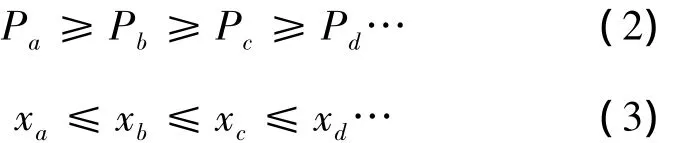
Triple gear and duplicate gear are usually used in the transmission system,the product of the numbers of gearing for each transmission group is equal to the product of the numbers of spindle levels.This relationship is represented in math formula according to its transmission sequence,where the ratio exponent written under the lower right corner of its gearing number.The ratio exponent of the first group is 1,so it is the base group;The exponent of the second one equals gearing number of the base group,so it is the first extending group;The exponent of the third one is equal the product of gearing numbers of base group and the first one,so is the second extending group,and so on.Consequently,formula(1)can be expressed by formula(4)according to consequence of both transmission and extending.

For example,formula(4)can have following possible from in convention transmission systems:
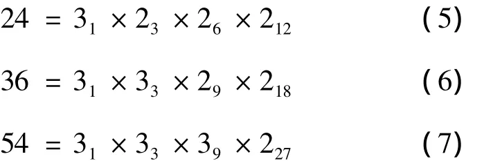
Here,take formula(5)as an example,its structural network is shown in Fig.1.
2 The reason for reinstitute the structural formulas of the main transmission system for machine tools
In the process of designing the main transmission system of machine tools,the speed range of any group in the structural formula is:

Where,rjis the speed range of any group;φ is common ratio;Pjis gearing number of any group;xjis ratio exponent of any group.
It is thus clear in formula(8)that the speed range is limited by both common ratio and ratio exponent.Common ratios φ can commonly be 1.41 or 1.26,while the last gearing numbers is 2,the ratio exponent xjto them is 6 or 9.The ratio exponent of third transmission group(second extending group)is 12 in corresponding structural network of Fig.1.Apparently it has greatly exceeded the maximum speed range limit.In practical application,when xj(that is P0P1P2…P(j-1))reached its limit value 6 or 9,it should not be increased anymore.It will cause a phenomenon of repeating in speed level.
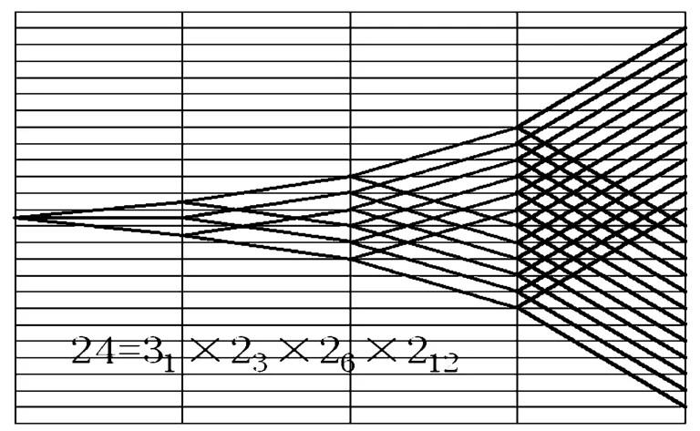
Fig.1 Structural network
When φ =1.41,the maximum ratio exponent corresponding to it is x2=6,the later one should and only be x3=6。There are 6 repeating speeds in the structural network,as shown in Fig.2 and its corresponding structural formula is18=31×23×26×26.It is obviously(obvious)that the equality sign and multiplication sign in the system with repeating speed transmission structure is impassability in mathematical explanation and are doubted in the reference [3-5]which raise a notion to improve the explanation of the formula but have not fundamentally solve the problem.It has not been adopted by the experts and authoritative books and manuals.Domestic machine tool desig-ning and teaching field has been in use of the traditional way of expression,and solving this problem and obsessing the designers are imperative.
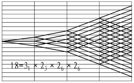
Fig.2 Repeating speeds and its structural formula
3 Exploration on reinstitute the structural formulas of the main transmission system for machine tools
3.1 Establish a general structural formula
In the process of setup a new calculating formula for the structural formula,the writer(authors)of this article tried to put forward a general formula which can be explained from mathematical and corresponds with its network visually correspondence.
Where,Z is the numbers of main transmission speed level of the machine tools;P0is the gearing number of the base group,the numbers of later ones can be deduced from this;x0is the ratio exponent of the base group,can deduce the rest from this.
It does not increase when the ratio exponent reaches its upper bound,and a correction term had been added to it.So the structural formula corresponding to the network in Fig.2 can be expressed in this way.
In order to guarantee that the transmission range don’t exceed the limit,the theoretical ratio exponent of last transmission group in formula(5)changed from 12 to 6 and the speed level and varied from 24 to 18 which can be spot directly.When the formula(9)needs further expanding,it can be written as following:
Formula(11)is more representative compared with the formula(9),for the numerator of the correction terms represents the repeating speed level and the denominator represents the theoretical ratio exponent of its transmission group.Adding a transmission group in the network of Fig.2 according to the formula(11),its corresponding formula become to the following form
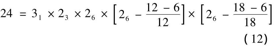
The network corresponding to formula(12)is shown in Fig.3.When φ =1.41 and corresponding maximum ration exponent x2=6,the main transmission system with 24 speed level needs 5 transmission groups to be realized.When the speed range of the second extending group (the third transmission group)reached its limit,the ratio exponents of following extending groups does not increased.The numerators of the correction terms represent the repeating speed level 6 and 12 respectively.
Fig.3 Network corresponding to formula(12)
3.2 Proving of the general formula in different transmission system
1)Proving in different common ratio and ratio exponent
According to the principal of transmission sequence with more in front and less at rear for the number of gearing,the last extending group must be a group with double speed level.If its limit value of the range is 8,then the ratio exponent should be 6 for a system with a common ratio of 1.41.If the common ratio is 1.26,then its ratio exponent reaches to 9.The conventional Formula can be 18=31×33×29,the total speed range is R=φZ-1=φ17=50.This is obviously not enough for most of the common machine tool.The ratio exponent of second extending group is 9 at this point,the speed range reaches its value limit 8.Increasing a group,its theoretical ratio exponent should be 18,but confined by its speed range,it still be 9 in practice.Its spindle speed level should be 36 in theory,but is 27 in fact,that has 9 repeating speed levels.Its conventional formula is 27 =31×33×29×29after adding an extending group.According to general formula(9)it can be written in the form of 27=3×3×2×),its corresponding to-139tal speed range is R= φZ-1= φ26=400,enlarged to 8 times,as shown in the network in Fig.4.This satisfied the requirement of total speed range for most general machine tools and verified the validity of formula(11)under different common ratios.
Fig.4 Network
2)Verified under a special transmission mechanism In the transmission system with its common ratio φ=1.41,if its ratio exponent needs to reach 8 a back wheels mechanism can be employed.Its formula is 16=21×22×24×28and the total speed range is R=φZ-1= φ15=180.In contrary the conventional formula was 12=31×23×26and its total speed range was R= φZ-1= φ11≈44 only.If a back wheels mechanism attach to it,there will have 4 repeating speed levels.The general formula is 20=31×23×and its network is shown in Fig.5.Its total speed range can be enlarged to 15 times.
Fig.5 Network
When φ =1.26,the conventional formula is 18=31×33×29.The ratio exponent can reach to 12 if a back wheels mechanism is adopted,then the conventional formula changed into 24=31×23×26×212.There will be 6 repeating speed levels if a back wheels mechanism added as shown in Fig.6.The general structural formula 30=31×33×29×(212-can also the validity and visually correspondence with its network.
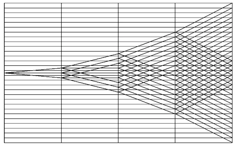
Fig.6 Network
4 Conclusions
1)The equality sign and multiplication sign possess mathematical meaning in the newly established structural formula of main transmission system for machine tool.
2)The formula suit for extending transmission system both conventional and with repeating speed levels.
3)It can be applied in the system with different common ratios.
4)It can be used in the special transmission system like back wheel mechanism.
5)The formula and network are truly visual correspondence.
Acknowledgements
This paper is supported by Natural Science Foundation of China(No.51175222,2012.01-2015.12).
[1]Dai shu.Metal cutting machine tool[M].Beijing:Machinery Industry Press,2000.
[2]Sui xiulin,Gao anbang.Handbook of machine design[M].Beijing:Machinery Industry Press,2010.
[3]Shi kangle.Research and recommend the main transmission chain structure[J].Journal of Nantong Institute of Technology,1996,12(1).
[4]Shi kangle,Shi yuanze.Discussion and recommendation of the main transmission system with coincident speed structure[M].Shanghai:Shanghai Machine tools,1995.
[5]Shi kangle,Shi yuanze.Study on the main transmission chain structure[J].Jiangsu:Mechanical science and technology,1996(6).
杂志排行

机床与液压的其它文章
- Research on comprehensive index system about product quality monitoring
- Visualization study of the oscillating bubble near the elastic wall
- Study on electro-hydraulic load simulator based on flow compensation method
- Optimal design for amplifier of jet deflector servo valve
- Availability function deployment of the CNC lathe based on multi factors
- Strict greedy design paradigm applied to the stochastic multi-armed bandit problem