Optimal design for amplifier of jet deflector servo valve
2015-09-17YaoxingSHANGXiaoshuZHANGChangweiHUShuaiWU
Yao-xing SHANG,Xiao-shu ZHANG,Chang-wei HU,Shuai WU
(School of Automation Science and Electrical Engineering,Beihang University,Beijing 100191,China)
1 Introduction
The jet deflector servo valve is a relatively new kind of electro-hydraulic servo valve,which mainly consists of the torque motor components,valve components and the deflection plate amplifier components [1-2].Compared with the current mainstream ones,such as the nozzle flapper servo valve and the jet pipe servo valve,It has more advantages[3-4].The main difference between jet deflector servo valve and the nozzle flapper servo valve structure lies in the structure of amplification stage,as shown in Fig.1.
Through controlling the position of the flapper,the nozzle flapper servo valve makes the nozzle generate different pressure so as to generate differential pressure at both ends of the valve spool which drives it moving.While the jet deflector servo valve makes the left and right receiving ports receive different pressure to generate differential pressure by adjusting the position of the deflection plate[5].It can be seen in Figure 1 that the minimum size of the nozzle flapper type is about 0.03 -0.05 mm,while that of the jet deflection plate type is about 0.2 -0.3 mm which is an order of magnitude higher than the former.So the larger particles impurities can easily get through which means the ability of resisting pollution of the jet deflector plate type is greatly improved[6].In addition,even if there is a blockage in the nozzle of the later,the valve spool will automatically return to the equilibrium position cause the left and right receiving ports receive nothing.But if a block age happens in a nozzle of the former,the wrong pressure makes a full rudder fault which indicates that the reliability of the nozzle flapper type is worse than the other.The usual jet pipe servo valve has bad dynamic characteristics because of its flexible jet pipe and has frequency characteristics usually less than 50 Hz[7].By using jet plate and deflector plate instead of flexible jet pipe,the dynamic characteristics of the jet deflector plate ones are improved and the frequency characteristics increase several times[8].The jet deflector servo valve has so many advantages that it is researched and the optimal design for the parameter of its amplification stage is put forward.

Fig.1 Different structures of valves’amplifier
2 Flow field modeling
2.1 Jet deflector servo valve flow field modeling
First of all,the inner structure and size of the amplification stage of the valve is studied by dismantling and learning a actual product.The valve mainly consists of armature assembly,deflector jet plate and the upper and lower blocks.In order to analyze the flow field,the inner flow field distribution should be analyzed firstly.Through using Solidworks,the whole flow field 3D model is successfully drew,as shown in Fig.2,according to what we have studied last step.
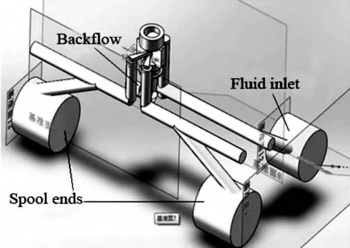
Fig.2 3D model of the flow field
2.2 Simplified model of the servo valve flow field
Fig.2 shows that the size difference between the minimum size position and the maximum size position is so large that it increases the difficulty to draw the mesh of the model or adds lots of analysis time of the flow field simulation.Whatever,it will lower our simulation efficiency.In fact,since the flow field near the jet plate has a narrow size and a complex structure which include a moving deflector plate unit,the main pressure and velocity changes of the whole model lie in where near jet plate.So only the flow field model near the jet plate is chose to be simulated and analyzed.The simplified model is shown in Fig.3.
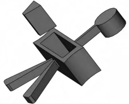
Fig.3 Simplified model
The mesh of the model can be easily drawn since simplified.And the number of the mesh is relatively small,which improves the efficiency of the simulation.While the simplifying model has little influence on the simulation accuracy according to what has been discussed last paragraph.Because the position of the deflector plate should be studied,the V groove unit of the model is set as movable unit to simulate the movement of the deflector plate.
3 Flow field simulation and analysis
3.1 Optimization parameters
It is difficult to fully define amplification stage of the valve.But several main structure sizes of the amplification stage such as the jet pipe length and width,the receiving ports space and the jet plate thickness have great influence on the performance of the valve[9-10],as shown in Fig.4.Also these sizes are relatively easy to be researched compared with the whole model structure.So these structure sizes of the amplification stage become our optimization objective.

Fig.4 Amplifier structure
3.2 Experiment method
First of all,we grouped the experiment according to the different structure size.In each group,the different size should be researched.In consideration of the experiment effect and efficiency,we choose three different sizes near the actual size to be analyzed at last.Then the flow field models are imported into Gambit for mesh drawing.The flow field varies by time cause the moving deflector plate.So it is necessary to simulate the movement of the deflector plate through the using moving V groove by setting the V groove as moving mesh.In the experiment,we select 20 positions during the deflector moving procedure for analyzing and data collection.
Next,we use Fluent to deal with the models.Considering the moving V groove,the unsteady flow model is selected.And the turbulent flow standard k-epsilon model is chose after analyzing the flow condition.According to commonly used oil,the oil density is set to 833 kg/m3and the oil viscosity is set to 0.000 61 kg/m·s.At last,the pressure of the inlet is set to 18 MPa and that of the outlet is set to 3 MPa according to the commonly used working parameters.Then we can start flow field simulation since all of the above has been done.During the simulation procedure,we need to take notice of the experiment residual error.When the residual error drops to the value set before the experiment or the number of iterations runs up to the value set,this simulation finishes.We record experiment data and repeat experiment until each size simulated.
4 Data analysis and fitting
4.1 Jet pipe length
In the experiment,0.4 mm,0.9 mm and 1.4 mm,these three different sizes are selected.Then we have three different flow field models,as shown in Fig.5.In each model,20 different positions of the moving V groove are chosen to get the relationship between the pressure of the valve and the displacement of the deflector plate when the jet pipe length varies.
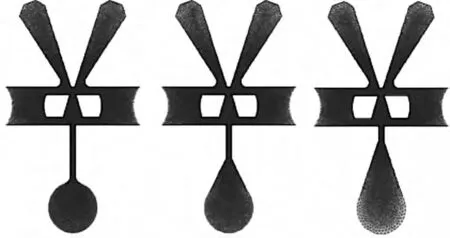
Fig.5 Models of different jet pipe length
We can learn the distribution of the velocity and pressure of the flow field at a certain point.Lots of information can be learnt on the distribution but too complex and discontinuous.In order to illustrate the condition briefly and accurately,the relationship between the varying experiment pressure and the displacement of the deflector is recorded in Table 1.
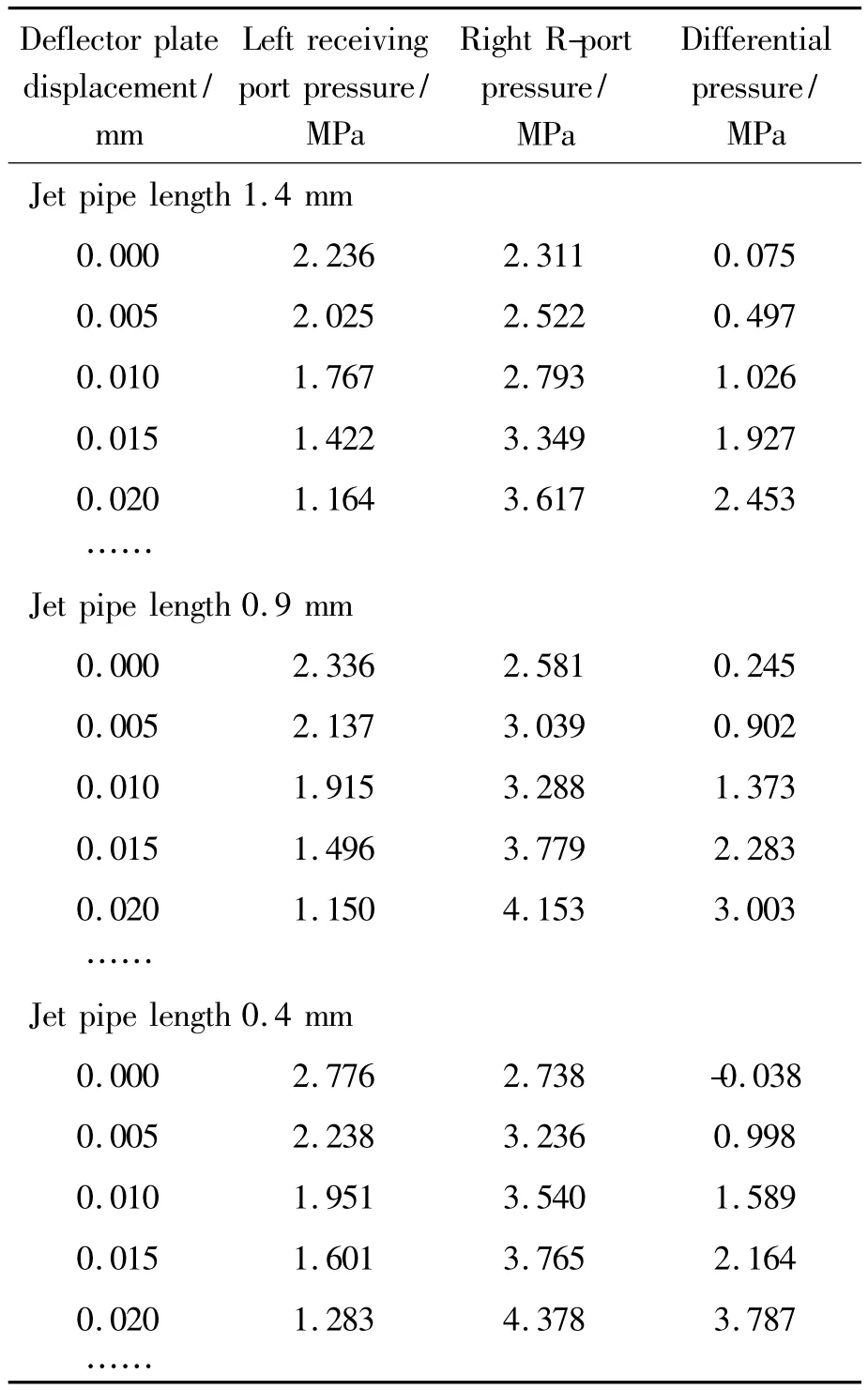
Table 1 Relationship between pressure and displacement
The differential pressure of the left and right receiving ports and how that varies by the deflector plate displacement can be used to learn the performance of the valve.For better comparison among three sizes,the differential pressure and the deflector plate displacement curves are drawn in one picture,as shown in Fig.6.It can be seen that the fluctuation of these curves are all slight,but the differential pressure of the 0.4 mm length one is larger than others when the deflector plate displacement is the same.That is,the shorter jet pipe length can produce larger output pressure.
Furthermore,the relationship among the differential pressure,jet pipe length and deflector plate displacement is drawn in a 3D picture and fitted into a smooth surface by using Matlab,as shown in Fig.7.We can know how the differential pressure varies by the jet pipe length and deflector plate displacement directly from the figure.Also we can fix a certain value of the deflector plate displacement to get the relationship between the pressure and the jet pipe length or slowly change the jet pipe length to analyze how the working curve changes.Then the better jet pipe length can be found by selecting the better working curve.So the working surface can be used to guide the size selecting during actual industrial design and production procedure.
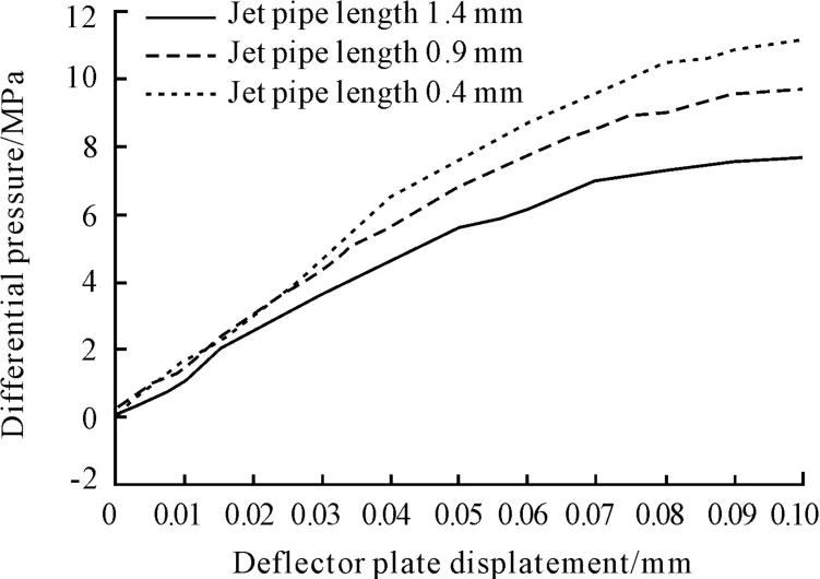
Fig.6 Pressure curves of different jet pipe length

Fig.7 Pressure surface
4.2 Jet pipe width
Just like the procedure of the jet pipe length experiment,0.1 mm,0.15 mm and 0.2 mm,these three different sizes are selected to build three different flow field models.In each model,20 different positions of the moving V groove are chosen to get the relationship between the pressure of the valve and the displacement of the deflector plate when the jet pipe width varies.The specific data relationship is also recorded in table and fitted in Fig.8.The picture shows that the 0.2 mm width curve is higher and more smooth which indicates the wider jet pipe makes the valve perform better.
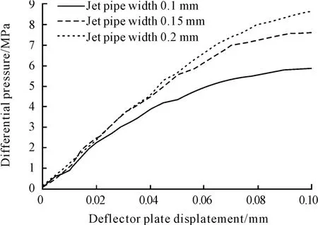
Fig.8 Pressure curves of different jet pipe width
4.3 Receiving ports space
Just like the procedure of the jet pipe length experiment,0.02 mm,0.06 mm and 0.1 mm,these three different sizes are selected to build three different flow field models.In each model,20 different positions of the moving V groove are chosen to get the relationship between the pressure of the valve and the displacement of the deflector plate when the receiving ports space varies.The specific data relationship is also recorded in table and fitted in Fig.9.It can be seen from the picture that the receiving ports space has little influence on the differential pressure but significant influence on the smoothness of the curves.In addition,the curve with wider receiving ports space has less fluctuation which means it has more stable performance.
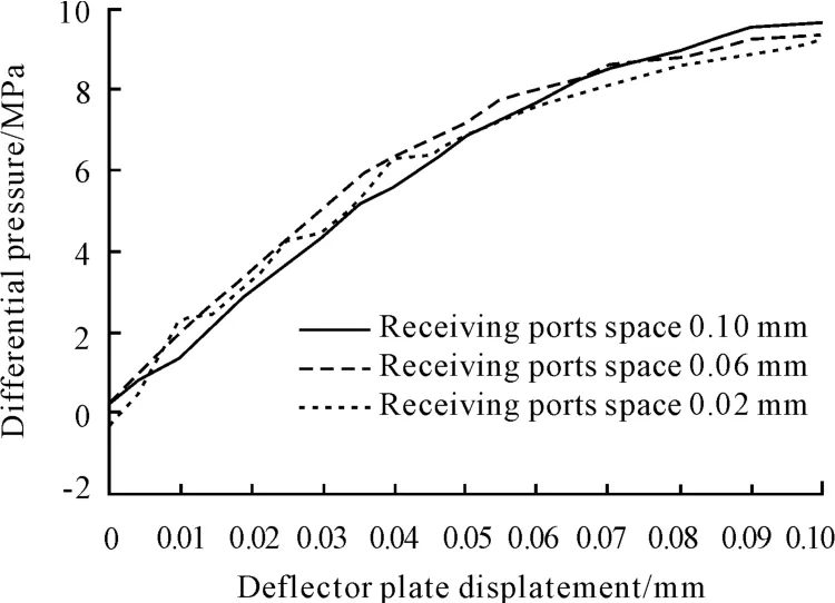
Fig.9 Pressure curves of different receiving ports space
The relationship among the differential pressure,receiving ports space and deflector plate displacement is also drawn in a 3D picture and fitted into a smooth surface by using Matlab,as shown in Fig.10.In the picture,we can easily find how the fold which indi-cates the steady performance of the valve varies by the receiving ports space.That is,the principle of selecting size is given by the picture.
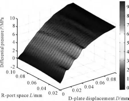
Fig.10 Pressure surface
4.4 Jet plate thickness
In this experiment,0.2 mm and 0.4 mm,these two different sizes are selected to build two different flow field models.In each model,20 different positions of the moving V groove are chosen to get the relationship between the pressure of the valve and the displacement of the deflector plate when the jet plate thickness varies.The specific data relationship is also recorded in table and fitted in Fig.11.The picture shows that the 0.4 mm thickness curve is higher than the other.So the more thick jet plate makes the valve perform better.
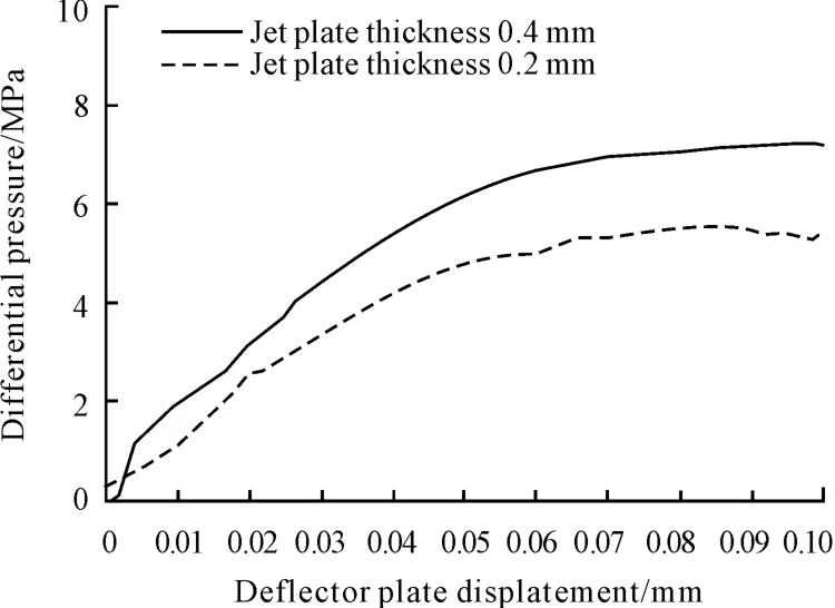
Fig.11 Pressure curves of different jet plate thickness
5 Conclusions
The jet pipe with larger width and smaller length lowers the pressure drop when fluid flows through itself so that receiving ports receive larger differential pressure.In addition,it leads to slighter fluid fluctuation.In consideration of other complex factors’influence on the valve’s performance,properly increasing the jet pipe width and decreasing its length contributes to the performance of the valve.
Through decreasing pressure fluctuation,the larger receiving ports space contributes a lot to improving the steady performance of the valve.And the more thick jet plate produce larger output pressure.Also considering some other factors not discussed in this paper,increasing receiving ports space and jet plate thickness in a certain range is good for improving valves’performance.
[1]Wang Zhanlin.Hydraulic servo system [M].Beijing:Beihang University Press,1987.
[2]Zhang Zhongsheng,Zhu Defu.Hydraulic servo mechanism[M].Beijing:National Defence Industry Press,1975.
[3]Tong Wenwang.Development direction of electro-hydraulic servo valve[J].Chinese Hydraulics & Pneumatics,1996.
[4]Fang Qun,Huang Zeng.Developing process,research actuality and trend of electro-hydraulic servo valve[J].Machine Tool& Hydraulics,2007.
[5]Li Zhuangyun.Hydraulic components and systems[M].Beijing:Mechanical Industry Press,2011.
[6]Huang Zeng,Hou Baoguo,Fang Qun,et al.Comparison of the jet pipe and nozzle flapper electro-hydraulic servo valve[J].Fluid Power Transmission and Control,2007.
[7]Wang Chuanli,Ding Fan,et al.The dynamic characteristic of jet plate servo valve controlled electro-hydraulic position system[J].Journal of Chongqing University,2003.
[8]Zhao Zhenhou,Zhang Jiyi.Brief survey about the situation of electro-hydraulic servo valve[J].Auxiliary electro-mechanical equipment of ship,1975.
[9]Yang Qiangqiang,Wang Wenhan.Exploration on processing technology of jet deflector servo valve’s amplifier[C]//The second civil aircraft manufacturing technology and equipment forum.Liaoning,1996.
[10]Zhang Rui,Li Changchun.Research on identification and optimal design of valve-controlled hydraulic servo system[J].Hydraulics Pneumatics& Seals,2014.
杂志排行
机床与液压的其它文章
- Research on comprehensive index system about product quality monitoring
- Exploration on the calculating formula of main transmission chain structural formulas of machine tools
- Visualization study of the oscillating bubble near the elastic wall
- Study on electro-hydraulic load simulator based on flow compensation method
- Availability function deployment of the CNC lathe based on multi factors
- Strict greedy design paradigm applied to the stochastic multi-armed bandit problem
