Study on electro-hydraulic load simulator based on flow compensation method
2015-09-17HuiANChengwenWANGXiaoxinHAOLongQUAN
Hui AN,Cheng-wen WANG,Xiao-xin HAO,Long QUAN
(Key Lab of Advanced Transducers and Intelligent Control System,Ministry of Education and Shanxi Province,Taiyuan University of Technology,Taiyuan 030024,China)
1 Introduction
Electro-hydraulic load simulator(EHLS)is used to simulate the external force acting on the moving loaded system under laboratory conditions.Due to the rigid connection of EHLS and the loaded system,the loaded system’s movement generates strong disturbance on EHLS.Usually the disturbance is called surplus force which is almost independent of the input signal.Surplus force,together with the force controlled by the input signal,makes up the output force,affecting the loading precision of EHLS.Surplus force is the key factor influencing the loading accuracy of EHLS[1].In order to eliminate surplus force to improve the loading accuracy of EHLS,many approaches have been developed up to now.One method is using accumulators to release the disturbance flow.However,it can only partially eliminate surplus force at the cost of reducing the dynamic response of loading system[2].Su and Wang[3-4]developed a novel load structure,in which another set position servo system was connected in series to EHLS for releasing the disturbance flow.The mechanical structure of the system is very complicated,and the cost is high.Chen [5]proposed a synchro-reverse method.It requires the two cylinders owning same dynamic characteristics and input signal.However,the complex drive mechanism of the compensation cylinder makes it difficult to be applied in practical engineering application.Besides,with the development of control technology,massive control methods,such as quantitative feedback theory[6-8],fuzzy technology[9],neural networks[10],and H∞mixed sensitivity theory[11],have been investigated for EHLS.For these control methods,the differential characteristic of surplus force leads compensation network containing high order differential links.High order differential links is difficult to be achieved on the physical structure and can be easily influenced by highfrequency noise.So the control methods can only achieve approximate compensation[12].
In this paper,on the basis of generating mechanism of surplus force,a flow compensation velocity circuit is added to the original system.The servo valve in the flow compensation velocity circuit is modified so that a high-performance velocity circuit can be achieved.This method avoids the forced movement induced surplus force by compensating it from the perspective of structure.
2 Basic description of EHLS
In general,the EHLS experiment is mainly composed by two sets of servo systems.i.e.,the loading system EHLS and loaded system.The work diagram of EHLS is illustrated in Fig.1.As shown in Fig.1,left part presents EHLS system including force servo circuit and flow compensation circuit.The two circuits are in parallel.The circuit of controlling force consists a hydraulic cylinder,servo valve and a force sensor,etc.While the flow compensation circuit is equipped with a hydraulic cylinder,servo valve with flow modified and a velocity sensor,etc.The right part denotes loaded system composed of a hydraulic cylinder,servo valve and a force sensor,etc.Essentially,the loaded system is a position servo control circuit.The input of the force control circuit is related to the motion of loaded system and its value is given by computer calculation,that is,by the load instruction production13 in Fig.1;the input of flow compensation circuit is given by velocity sensor from hydraulic cylinder of the loaded system.The loading cylinder produces the force to simulate the load acting on the control surface of loaded system.Obviously,the force tracking performance is subject to loaded system’s active motion.
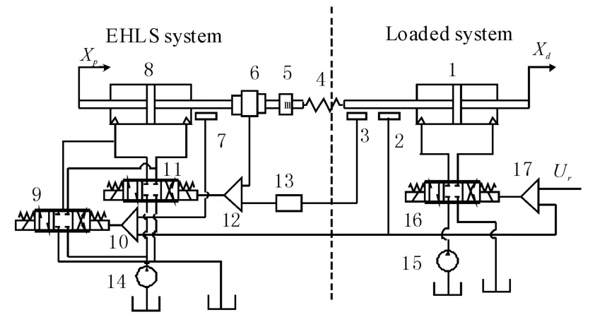
Fig.1 Electro hydraulic load simulator work diagram
3 Mathematic model
3.1 Modify the flow of servo valve in flow compensation velocity circuit
According to the literature[13],the flow of servo valve in compensation circuit is modified utilizing the pressure difference between valve ports.Firstly,without the modification circuit,the flow equation of the servo valve is:
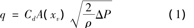
The Eq.(1)shows that the output flow q varies with the pressure difference of servo valve ports ΔP.Thus the actual output flow of servo valve deviates from the ideal output flow which finally affects the controlling accuracy of the compensation circuit.Flow changes caused by the changed flow area can offset the changes caused by the pressure difference by adjusting the servo valve opening degree accordingly.Then the output flow can be maintained.
For the servo valve,and the relationship between A(xv)and the deviation signal e is A(xv)=Kxe.According to the Eq.(2),we modify the gainKx:

Where,Kpis the open-loop gain through modif-ying,PNis the pressure difference corresponded to servo valve rated flow,So the flow equation of modified servo valve is:

Where,Kjqis the flow gain of modified servo valve.
From the Eq.(3),it can be known that the flow of modified servo valve only has a linear relationship with its open area.No longer affected by the pressure drop at servo valve ports,the flow of modified servo valve has a linear relationship with input(current).
3.2 Build mathematic model of the whole system
The linearization flow equation of the servo valve in force circuit is:

Where,qlis valve load flow from force circuit(m3/s),Kqis valve flow gain in force circuit(m2/s),Kpis valve flow-pressure coefficient in force circuit(m5/(N·s)),plis valve load pressure of load hydraulic cylinder in force circuit(N/m2),xv1is valve spool position in force circuit(m).The linearization flow equation of the modified servo valve in the flow compensation circuit is

Where,qsis valve load flow from compensation circuit(m3/s),Kjqis valve flow gain in compensation circuit(m2/s),xv2is spool position in compensation circuit(m).
Equation of the flow into the hydraulic cylinder is as follows.

Where,qgis total flow into hydraulic cylinder(m3/s),Apis effective area of hydraulic cylinder(m2),Vtis total effective volume of loading system(m3),βeis effective bulk modulus of oil(N/m2),Ctpis total leakage coefficient of loading system(m5/(N·s)),xpis the displacement of loading system(m).
The moment balanced equation of hydraulic cylinder:

Where,mtis the mass of the piston components(kg),Bpis viscous damping coefficient between the piston and the load(kg/s),K is the load spring stiffness(N/m),xdis the displacement of tested system(m).
The actual output force of loading system is:

Power sources of the hydraulic cylinder,include force circuit and flow compensation circuit,so:

The open-loop system transfer function of EHLS with flow compensation is obtained through the Laplace transformation for the above Eqs.(4)-(9):
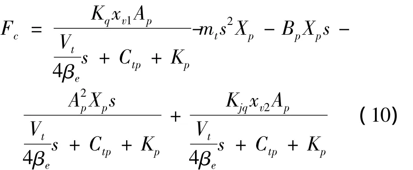
For Eq.(10),the first item is the output force controlled by servo valve in the force circuit.The middle three parts are surplus force.The first four items constitute the finally output force of EHLS without flow compensation,the last one is the compensation for surplus force from the compensation circuit.
Through neglecting the leakage,the elastic compression,viscous friction and hydraulic cylinder piston weight,the open-loop system transfer function of EHLS with flow compensation can be simplified as:

According to Eqs.(11)(12),transfer function of EHLS with compensation circuit can be shown as:

Eq.(13)implies that surplus force could be eliminated completely when the flow from flow compensation circuit matches well with the forced flow.On the basis of Eq.(13),closed-loop control block diagram of EHLS with flow compensation is given as Fig.2.

Fig.2 Closed-loop control block diagram of EHLS with flow compensation
4 Simulation model
The parameters of hydraulic cylinder in the loaded system are the same as the cylinder parameters of EHLS.The frequency and damping ratio of all the servo valves following are the same.Simulation parameters are as the following Table 1.
To value the effectiveness of the developed method,the simulations are performed by SimulationX.The simulation model is shown in Fig.3.In the figure,the function block f(x)measures the pressure of the hydraulic cylinder of loading system as a feedback to input signal to realize closed loop control.The connection stiffness between the loaded system and EHLS can affects the value of surplus force.Reducing the stiffness can decrease the surplus force.But at the same time it can lead amplitude attenuation and phase lag of the loading force[14].So with the reducing of stiffness,the quick response and the bandwidth of EHLS are all reduced.This paper sets up the connection stiffness of 6 300 000 N/m.The system pressure is 210 bar.Through calculation,this system velocity can reach 364 mm/s,output force reach up to 28 850 N.
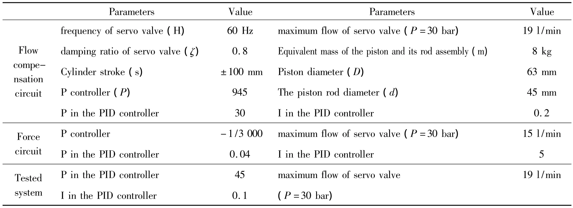
Table 1 Simulation parameters

Fig.3 The simulation model of EHLS with flow compensation
5 Simulation analysis
5.1 Simulation analysis of the flow compensation circuit
Depending on the require of position/velocity circuit,the zero opening valve with a good displacementflow characteristic is chosen for the flow compensation circuit and loaded system.Based on the modified servo valve,simulation model of flow compensation circuit is established combining PID control.Adjusting the PID parameters,velocity of EHLS can match well with loaded system’s velocity.Fig.4 shows the comparison of input velocity signal of EHLS,its output velocity signal and the velocity of loaded system on the condition of no force circuit.As shown in the Fig.4,the output velocity signal of loaded system can track the input signal accurately;the velocity system of EHLS can match well with the velocity of loaded system.As illustrated from the simulation result,the velocity circuit owns high accuracy and frequency.
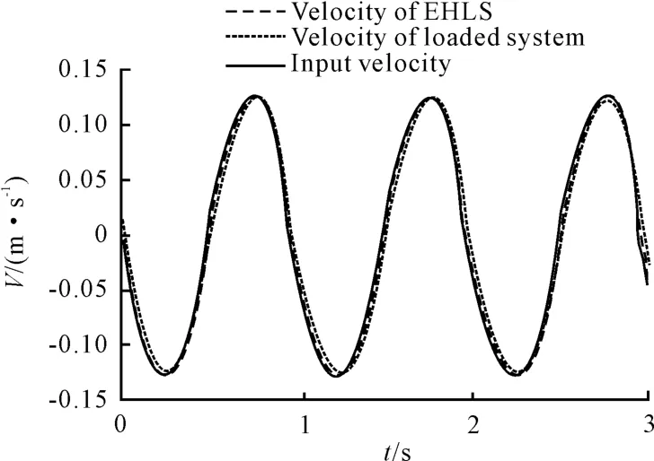
Fig.4 The simulation result comparison of the flow compensation circuit
5.2 Simulation analysis of the force circuit
The pre-opening flow servo valve owns characters of large flow gain,low pressure sensitivity and much leakage at zero relative valve stroke.These characters are just needed by the force circuit for reducing partial surplus force[15].The same to the paragraph 4.1,the force simulation circuit is built up combining PID.Adjust the PID parameters to achieve the desired state.In the Fig.5,a step signal F=10 kN is given to the force circuit.The Fig.5 shows the time response of force circuit time is 60 ms.
5.3 Analysis of the simulation result
According to Eq.(13),the surplus force is mainly influenced by the velocity of loaded system.So for the input signal,greater amplitude leads to greater surplus force;greater signal frequency leads to greater surplus force.The displacement signal of loaded system is set to series sinusoidal signal of different amplitudes and frequencies.While the input force signal instruction is set to 0,the output force of EHLS is the surplus.Fig.6 illustrates the comparison of surplus forces in different methods.One is the surplus force of EHLS with flow compensation and PID;the other one is the surplus force of EHLS only with PID.The frequency of given instruction signal is respective 1 Hz,5 Hz,or 10 Hz.

Fig.5 The time response curve of force circuit
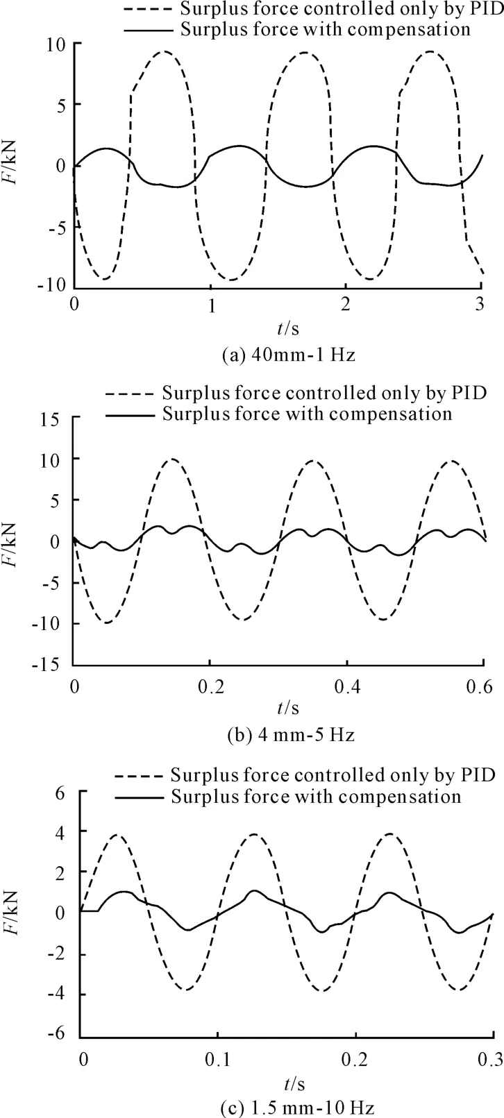
Fig.6 Simulation comparison of surplus force
The motion of loaded system forces EHLS moving together with it,which leads the oil pressure of one cavity of hydraulic cylinder increase hugely.The preopen flow servo valve chosen by the authors can release some forced flow.In spite of the little effect of the servo valve,huge surplus force is still there,that is,the curve‘surplus force controlled only by PID’,as shown in Fig.6.In this paper,a modified servo valve with good flow characteristic is used to compensate the forced flow.The flow compensation velocity circuit eliminate the relatively motion between loaded system and EHLS,avoiding the generation of surplus force.So the surplus force with flow compensation is hugely decreased as shown in Fig.6
6 Conclusions
In this paper,the flow compensation circuit is added to EHLS aiming at reducing the surplus force.Paralleled with the original force circuit,the flow compensation circuit controls the velocity of EHLS specifically to avoid the generation of forced flow.In order to achieve high-performance for the compensation circuit,the servo valve in the compensation circuit is modified.The flow error caused by pressure difference is eliminated for the modified servo valve.As a result,it makes the flow compensation circuit own high tracking accuracy.Then the mathematical model of EHLS with flow compensation is built.From the mathematical model,the feasibility of this method is verified in theory.Based on these work,the physical simulation model of the system is established.The simulation results imply that the surplus force of the control strategy in this article is less than 30%to the one only controlled by PID under different frequencies from 1 Hz to 10 Hz.The simulation results also demonstrate its effectiveness.
Acknowledgements
This paper is supported by National Natural Science Foundation of China(51075291)and The Natural Science Foundation of Shanxi Province(2008011053)Funded Project.
[1]Hua Qing.Research on the key problems of t he electro hydraulic load simulator[D].Beijing:Beijing University of Aeronautics and Astronautics,2001.
[2]Gao Junxia,Hua Qing,Jiao Zongxia.The problem of sur-plus torque and the comparison of various compensation methods of electro-hydraulic loading system[J].Hydraulics Pneumatics&Seals,2003(3):13 –17.
[3]Su Donghai,Wu Shenglin,FU Xingwu,et al.Eliminating disturbance torque by angular velocity difference based on synchronization compensation[J].Journal of Harbin Institute of Technology,2000,32(1):78-81.
[4]Zhang Lixun,Meng Qingxin,Liu Qinghe,et al.Position synchronization compensation method for widening the bandwidth of aeroload simulator[J].Journal of Astronautics,1997,18(1):120-123.
[5]Chen Hengquan.Use the synchronous reverse method to overcome the surplus torque[J].Machine Tool& Hydraulics,1985(3):13-17.
[6]Yoonsu Nam,Sung Kyung Hong.Force control system design for aerodynamic load simulator[J].Control Engineering Practice,2002,10(5):549–58.
[7]NAM Y S.QFT force loop design for the aerodynamic load simulator[J].Transactions on Aerospace and Electronic Systems,2001,37(4):1384-1392.
[8]Karpenko M,Sepehri N.On quantitative feedback design for robust position control of hydraulic actuators[J].Control Engineering Practice,2010(18):289-299.
[9]Dinh Quang Truong,Kyoung Kwan Ahn,Kim Jung Soo,et al.Application of fuzzy-PID controller in hydraulic load simulator[C]//International conference on mechatronics and automation,2007.ICMA 2007.IEEE;2007:3338-3343.
[10]Jiao Zongxia,Hua Qing.RBF neural network control on electro-hydraulic load simulator[J].Journal of Mechanical Engineering,2003,39(1):10-14.
[11]Li Geqiang,Cao Jian,Zhang Biao,et al.Design of robust controller in electrohydraulic load simulator[C]//2006 international conference on machine learning and cybernetics.IEEE;2006:779-784.
[12]Zhang Wei,Research on the control methods of elec trohydraulic load simulator[D].Xi’an:Northwestern Polytechnical University,2007.
[13]Quan Long,Zhou Wei,LinTingqi,et al.The principle and application of detecting dynamic flow with pressure difference[J].Journal of Electronic Measurement and Instrument,1994,8(3):17-22.
[14]Hao Jingjia,Zhao Keding.Study on the Influence of Rigidity and Inertia in Electro-hydraulic Load Simulator[J].Journal of Mechanical Engineering,2003(6):458-461
[15]Li Geqiang,Han Jianhai,ZHANG Biao,et al.The LoadA-pplication of Open Center Spool Valve in Electrohydraulic Simulator[J].Chinese Hydraulics& Pneumatics,2008(12):42-45.
杂志排行

机床与液压的其它文章
- Research on comprehensive index system about product quality monitoring
- Exploration on the calculating formula of main transmission chain structural formulas of machine tools
- Visualization study of the oscillating bubble near the elastic wall
- Optimal design for amplifier of jet deflector servo valve
- Availability function deployment of the CNC lathe based on multi factors
- Strict greedy design paradigm applied to the stochastic multi-armed bandit problem