液化侧扩流场地桥梁群桩效应分析①
2015-06-09刘春辉凌贤长
刘春辉, 唐 亮,2, 凌贤长
(1.哈尔滨工业大学土木工程学院,黑龙江 哈尔滨 150090;2.成都理工大学地质灾害防治与地质环境保护国家重点实验室,四川 成都 610059)
液化侧扩流场地桥梁群桩效应分析①
刘春辉1, 唐 亮1,2, 凌贤长1
(1.哈尔滨工业大学土木工程学院,黑龙江 哈尔滨 150090;2.成都理工大学地质灾害防治与地质环境保护国家重点实验室,四川 成都 610059)
基于u-p有限元公式模拟饱和砂土中水和土颗粒完全耦合效应,建立液化侧向流场地群桩动力反应分析的三维数值模型。模型中,砂土采用多屈服面弹塑性本构模型模拟、黏土采用多屈服面运动塑性模型模拟,群桩在计算过程中保持线弹性状态;采用20节点的六面体单元和考虑孔压效应的20-8节点分别划分黏土层和饱和砂层;选用剪切梁边界处理计算域的人工边界,模拟地震过程中土层的剪切效应;应用瑞利阻尼考虑体系的阻尼效应。随后对比分析2×2群桩中各单桩的地震反应规律,结果表明,各单桩的弯矩、位移时程规律基本一致,峰值弯矩及峰值位移出现时刻滞后于输入加速度峰值时刻,上坡向桩的弯矩和位移峰值大于下坡向的桩的反应值。接着通过改变桩间距研究群桩效应,随着桩间距增加,群桩中各单桩的弯矩最大值均出现在土层分界处,且各单桩的弯矩、桩顶位移逐渐增大。最后给出液化侧向流场地群桩效应的基本原因,得出该类场地群桩抗震设计的基本认识。
群桩效应; 液化侧向流动; 桩-土相互作用; 地震; 非线性三维有限元分析
0 引言
历次强震(如1964年阪神地震、1987年新西兰地震、1995年神户地震、1999年台湾集集地震)震害调查表明[1-5],液化侧向流动是造成大量桥梁桩基严重破坏的主要原因。因此液化侧向流场地桥梁桩基破坏便成为岩土地震工程领域的重要研究问题。为了考察地震作用下液化侧向流场地桩基破坏机制,众多学者如McVay[6]、Rollins[7]、Tokimatsu[8]、Suzuki[9]、Ashford[10]及Abdoun[11]分别采用振动台试验和人工控制爆炸的方式研究液化侧向流场地桩的侧向承载特性。然而鲜有文献定量研究液化侧向流场地中群桩效应以及桩间距对群桩中各桩受力特性的影响。因此,本文采用三维有限元法研究液化侧向流场地2×2群桩地震反应特性,分析前、后桩的受力差异,考察桩间距对群桩效应的影响状况,剖析液化侧向流场地群桩效应的基本原因。
1 群桩动力反应数值模拟与分析
1.1 数值模型
所有计算均基于OpenSees有限元计算平台实现。模型中采用多屈服面模型(J2)考虑饱和砂土的非线性。该模型能够考虑液化引起中密砂、密砂永久剪应变积累效应,并引入合适的加载-卸载流动法则模拟循环荷载输入下砂土的偏体应变耦合效应(膨胀砂土的收缩、理想塑性和膨胀特性),可以重现试验中观察在大的循环剪切荷载输入下砂土出现的明显膨胀趋势及循环剪切刚度和强度增大(循环流滑机理)的现象。黏土视为非线性滞回材料,采用Von Mises多屈服面运动塑性模型模拟,塑性公式基于多屈服面概念提出,采用关联流动法则。该模型中土体塑性仅在偏应力-应变响应下产生,体应力-应变响应为线弹性,且与偏应变响应独立,其能够模拟土体的单调及循环响应。模型中砂土和黏土参数见表1。
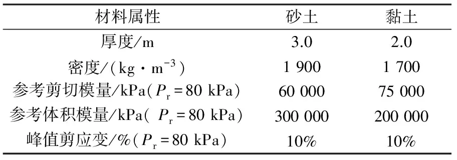
表1 土体计算参数
为缩短计算时间,利用模型的对称性建立液化侧向流场地群桩动力反应分析的有限元模型(图1)。模型包括两层土,上部为3 m厚的饱和砂层,下部为2 m厚的黏土层。地表倾斜3°。模型长和宽均为15 m。地下水位线位于地表处。
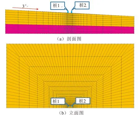
图1 有限元模型Fig.1 The finite element model
模型中采用有限元u-p方程(p为砂土的孔压,u为土颗粒位移)模拟饱和砂土的液化过程[14];采用考虑孔压效应的20-8节点和不考虑孔压效应的20节点六面体等参单元分别剖分砂土层和黏土层。桩径0.3 m,桩长5 m,其中地上部分0.5 m。桩顶处于自由状态,不考虑承台的约束效应。桩采用线弹性梁-柱单元模拟,弹性模量为2.08×10⁷kPa,惯性距为3.98×10⁻⁴m4,密度为2 400 kg/m3,桩与土采用径向辐射状杆单元连接[12]。
沿着振动方向的人工边界采用剪切梁边界,模拟地震中土层的剪切效应[12];土体底面、侧面均为不透水边界;垂直于振动方向的对称面和外面上的土体不在该平面外发生变形。计算中先施加重力,随后在模型底部输入El Centro地震波激励,加速度时程见图2。
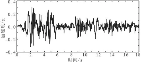
图2 基底输入的El Centro地震波Fig.2 El Centro wave input in the basement
使用瑞利阻尼C=αM+βK(β为刚度比例系数,α为质量比例系数)考虑体系的阻尼特性,本文取α=0.062,β=0.006。计算中采用位移收敛准则作为计算依据。
上述数值建模途径已采用在大型层状剪切土箱(12 m(长)×6 m(高)×3.5 m(宽))完成的液化侧向流动场地桩基动力反应振动台试验验证[13]。
1.2 桩的弯矩反应
不同深度处桩的弯矩时程见图3,可见桩的最大弯矩出现在4.89s,滞后于基底输入加速度的峰值时刻(由图2可知,峰值加速度时刻为2s)。这是由于地震引起土体液化,场地表面倾斜,造成土体发生侧向流动,在峰值加速度出现时刻土体仍在流动,因此桩的弯矩不断增加,在第二个加速度峰值(4.89s)处桩的弯矩也达到峰值。由图还可以看出,在达到峰值弯矩之后桩的弯矩逐渐减小,但在地震动输入结束之后仍有一定残余弯矩。这是由于桩的抗弯刚度较大,土体发生液化后丧失抗剪切能力,因此在达到峰值弯矩之后桩逐渐回弹,弯矩逐渐减小,但由于土体仍存在一定强度,因此在地震动输入结束后桩的弯矩值并不为零。
比较桩1与桩2的弯矩时程可见,二者弯矩随时间变化规律基本一致,都与输入加速度时程关系密切。由图3(a)和(b)得到,弯矩随深度变化的规律也基本一致,都是在靠近土层分界处大,在地表及模型底部桩的弯矩接近于零。
1.3 桩的位移反应
不同深度处桩的位移时程如图4所示,由图可以看出桩的位移最大值出现时刻在4.89s,与弯矩峰值出现时刻一致,滞后于输入加速度峰值时刻。桩的位移在靠近地表处最大,随着深度增加逐渐减小,说明液化后上层砂土发生流动产生的位移要大于较深处砂土产生的位移;在4.5m深度处桩的位移接近于零,说明黏土层产生的位移很小,并且2m厚的黏土层对桩有较强的约束作用。
比较图4(a)与(b)可见,桩1的位移反应要大于桩2,这一结论与现有研究结果相符,这是由于桩1处于上坡向,由于“阴影效应”,桩1对桩2有一定“保护”作用,所以桩1所承受的土体侧向力大,桩2则较小。
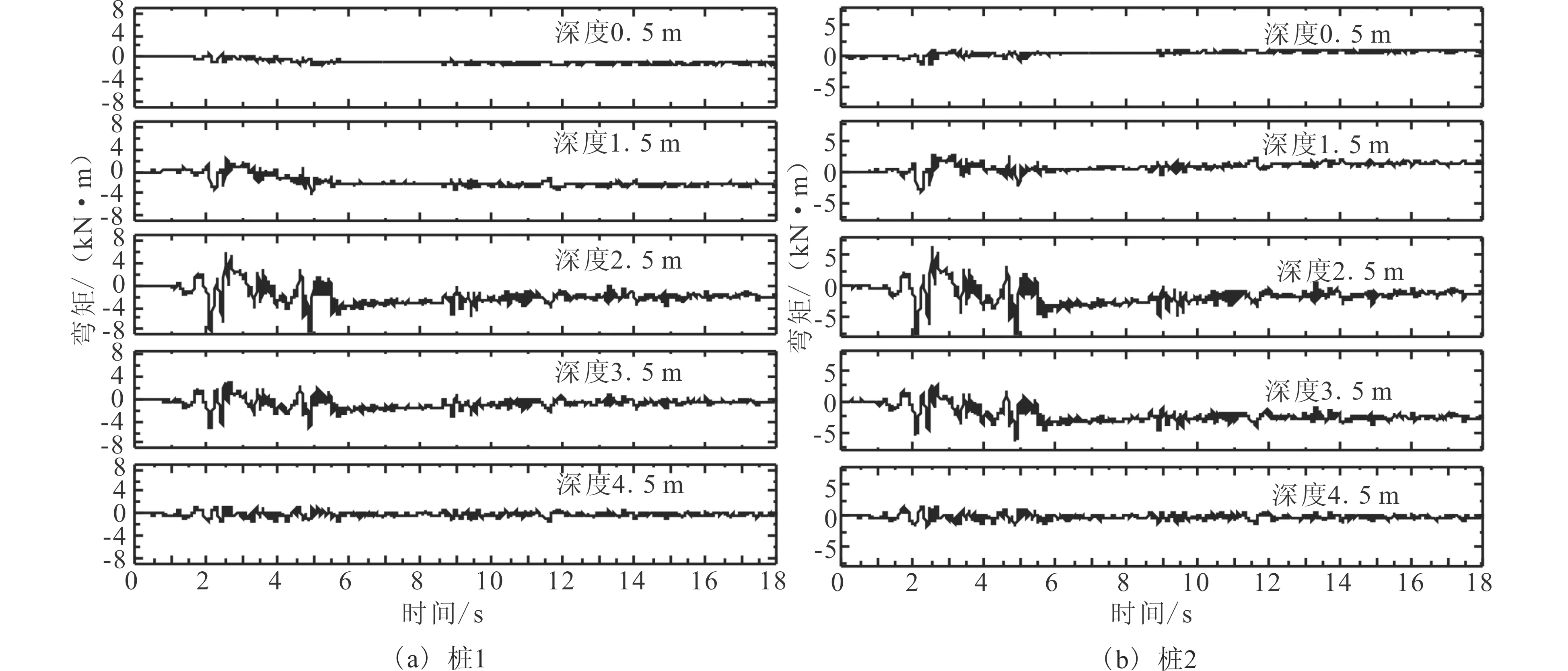
图3 桩的弯矩时程Fig.3 Bending moment time-history of piles
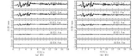
图4 桩的位移时程Fig.4 Displacement time-history of piles
2 桩间距对桩的反应的影响
将桩间距为3D、5D、7D(D为桩径)的群桩进行模拟,进一步考察桩间距对群桩效应的影响,其弯矩随深度变化规律见图5。图中3D-桩 1代表桩间距为3倍桩径的群桩中第一个桩的弯矩,其他各符号意义类似。由图可以看出,弯矩随着深度的增加先增大后减小,峰值弯矩出现在桩土分界面处,这一结果与现有理论及我国抗震规范规定一致[15]。比较不同桩间距的群桩中各单桩的弯矩可以看出,随着桩间距增大,桩基弯矩峰值逐渐增大,这是由于随着桩间距增大“阴影效应”逐渐减弱,群桩中各单桩地震响应逐渐与单桩响应接近。比较相同桩间距群桩中各单桩峰值弯矩可以看出,桩1(上坡向的桩)弯矩峰值要大于桩2(下坡向的桩),并且随着桩间距增大,群桩中各单桩的峰值弯矩差值逐渐减小,这说明随着桩间距增大,群桩中各单桩地震弯矩响应逐渐接近,群桩中各单桩响应特性逐渐与单桩相同。

图5 群桩中各单桩最大弯矩随深度变化规律Fig.5 Maximum bending moment versus depth of individual pile in pile group
为比较不同桩间距群桩中各单桩峰值弯矩的差值,本文对深度3 m处的峰值弯矩进行归一化处理,结果如图6所示,图中符号所代表意义与图5相同。由于在本文分析中7倍桩间距群桩中桩1的弯矩最大,以其为基准进行归一化。由图可以看出,在7倍桩间距下两单桩的弯矩峰值非常接近,仅仅相差3%;而在3倍桩间距群桩中两单桩的弯矩峰值差别最大,相差10%;在5倍桩间距群桩中弯矩峰值相差4%左右。因此,在液化侧向流场地桩基设计中,在保证安全的前提下,应当考虑桩间距较小时群桩中各单桩动力响应的不同,提高建设的经济性,群桩桩间距较大时不应考虑各单桩响应的差异。
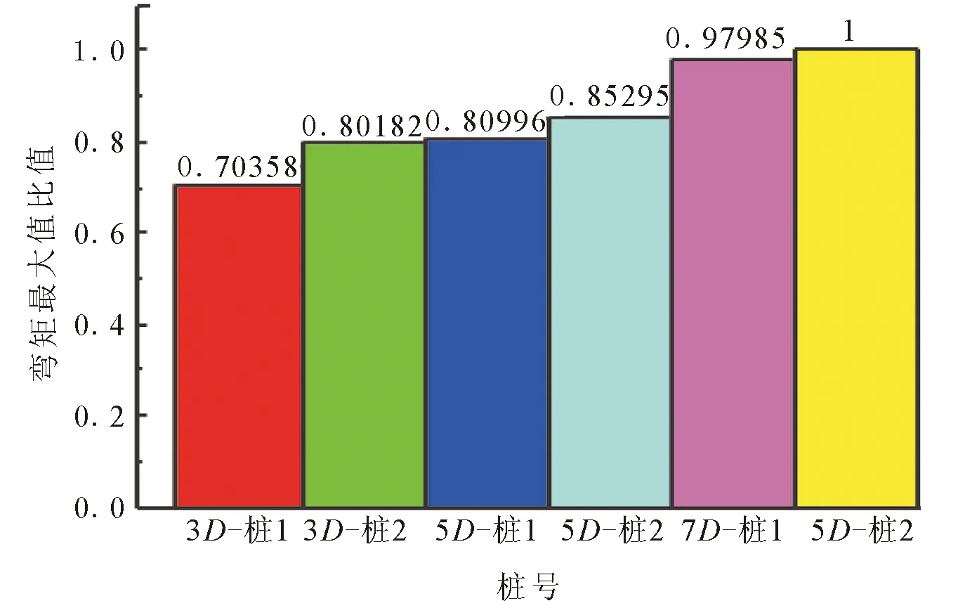
图6 不同桩间距群桩中各单桩峰值弯矩比较Fig.6 Maximum bending moment of individual pile in pile group of different pile spacings
3 结论
采用非线性有限元方法对地表倾斜3°的液化侧向流场地2×2群桩地震反应进行分析,得到以下结论:
(1) 液化侧向流场地中,群桩的地震反应与输入地震动密切相关,桩的峰值弯矩和峰值位移出现时刻滞后于输入地震动的峰值时刻。
(2) 场地为上层饱和砂土下伏黏土的液化侧向流场地中,桩顶自由的群桩峰值弯矩出现在土层分界处,峰值位移出现在桩顶处。
(3) 相同地震动输入下,随着桩间距增大,群桩中各单桩峰值弯矩逐渐增大,且均出现在桩土分界面位置。
(4) 随着桩间距增大,群桩中各单桩峰值弯矩差异逐渐减小;当桩间距为7倍桩径时二者差异仅为3%,此时可忽略群桩中单桩响应差异。
(5) 桩间距较小时群桩中各单桩弯矩反应差别较大,建议在进行液化侧向流场地中桩基抗震设计时考虑群桩中各单桩地震响应差异。
References)
[1] Hamada M,Yasuda S,Isoyama R,et al.Study on Liquefaction Induced Permanent Ground Displacements[M].Tokyo:Association for the Development of Earthquake Prediction,1986.
[2] Tokimatsu K,Asaka Y.Effects of Liquefaction-induced Ground Displacements on Pile Performance in the 1995 Hyogoken-Nambuearthquake[J].Soilsand Foundations,1998,(Special issue):163-77.
[3] Ishihara K.Terzaghi Oration:Geotechnical Aspects of the Kobe Earthquake[R].Proc,ICSMFE,Hamburg,1995:2047-2073.
[4] Idriss I M,Abrahamson N A.7 Geotechnical Aspects of the Earthquake Ground Motions Recorded During the 1999 Chi-chi Earthquake[C]//Proc Int Workshop on Annual Commemoration of Ji-Ji Earthquake,National Center for Research on Earthquake Engineering.2000,18(20):9-22.
[5] He L,Elgamal A,Abdoun T,et al.Liquefaction-induced Lateral Load on Pile in a Medium Dr Sand Layer[J].Journal of Earthquake Engineering,2009,13:916-38.
[6] McVay M,Zhang L,Molnit T,et al.Centrifuge Testing of Large Laterally Loaded Pile Groups in Sands[J].Journal of Geotechnical and Geoenvironmental Engineering,1998,124(10):1016-1026.
[7] Rollins K M,Gerber T M,Lane J D,et al.Lateral Resistance of a Full Scale Pile Group in Liquefied Sand[J].Journal of Geotechnical and Geoenvironmental Engineering,2005,131(1):115-125.
[8] Tokimatsu K,Suzuki H.Pore Water Pressure Response Around Pile and Its Effects onp-yBehavior During Soil Liquefaction[J].Soils and Foundations,2004,44(6):101-110.
[9] Tokimatsu K,H Suzuki,M Sato.Effects of Inertial and Kinematic Interaction on Seismic Behavior of Pile with Embedded Foundation[J].Soil Dynamics and Earthquake Engineering,2005,25(7-10):753-762.
[10] Ashford S A,Juirnarongrit T,Sugano T,et al.Soil-pile Response to Blast-induced Lateral Spreading.I:Field Test[J].Journal of Geotechnical and Geoenvironmental Engineering,2006,132(2):152-162.
[11] Abdoun T, Dobry R, O’Rourke T,et al.Single Piles in Lateral Spreads: Field Bending Moment Evaluation[J].Journal of Geotechnical and Geoenvironmental Engineering,2003,129(10):879-89.
[12] 唐亮,凌贤长,艾哈迈德·艾格玛.液化侧向流动场地桩基动力反应振动台试验三维有限元数值模拟方法[J].土木工程学报,2013,46(S1):180-184.TANG Liang,LIANG Xian-zhang,Ahmed Elgamal.Three-dimensional Finite Element Analysis of Shake-TableTest for Dynamic Pile Behavior in Liquefaction-induced Lateral Spreading Ground[J].China Civil Engineering Journal,2013,46(S1):180-184.(in Chinese)
[13] 唐亮,凌贤长,徐鹏举,等.液化场地桩-土地震相互作用振动台试验数值模拟[J].土木工程学报,2012,45(增刊1):302-306.TANG Liang,LIANG Xian-zhang,XU Peng-ju,et al.Numerical Simulation of Shaking TableTest for Seismic Soil-pile Interaction in Liquefying Ground[J].China Civil Engineering Journal,2012,45(Supp1):302-306.(in Chinese)
[14] 唐亮.液化场地桩-土动力相互作用p-y曲线模型研究[D].哈尔滨:哈尔滨工业大学,2010.TANG Liang,p-yModel of Dynamic Pile-soil Interaction on Iiquefying Ground[D].Harbin:Harbin Institute of Technology,2010.(in Chinese)
[15] 中华人民共和国行业标准编写组.GB 50011-2010,建筑抗震设计规范[S].北京:中国建筑工业出版社,2010.Standars Complication Group of People’s Republic of China.GB 50011-2010,Code for Seismic Design of Buildings[S].Beijing:China Architecture & Building Press,2010.(in Chinese)
Analysis of the Bridge Pile Group Effect in Liquefaction-induced Lateral Spreading Sites
LIU Chun-hui1, TANG Liang1,2, LING Xian-zhang1
(1.SchoolofCivilEngineering,HarbinInstituteofTechnology,Harbin,Heilongjiang150090,China;2.StateKeyLaboratoryofGeologicalDisasterPreventionandGeologicalEnvironmentProtection,ChengduUniversityofTechnology,Chengdu,Sichuan610059,China)
The Finite Element method was used to analyze the dynamic response of pile groups in the ground subjected to the liquefaction-induced lateral flow of soils.Theu-pFinite Element formulation was used to depict the coupling effect of water and sand soil particles in the Finite Element analysis.A 3D numerical model was developed to analyze the effect of a 2×2 pile group subjected to liquefaction-induced lateral spreading.In this model,sand was simulated using a pressure-independent multi-yield surface plastic model.Clay material served as a nonlinear hysteretic material with a multi-surface kinematic plasticity model,and the pile group maintained its linear behavior in the process of calculation.The clay layer and saturated sand layer were meshed in a 20-node brick element and separately in a 20-8 node element.The boundary of the numerical model was considered as the shear beam boundary,which simulated the shear effect of the soil layer during the earthquake.Finally,the Rayleigh damping method was used to model the damping of the system.The dynamic response of each pile in pile group was compared,and it showed that the bending moment and displacement time history of piles at different depths developed in the same way,and the time of maximum bending moment and displacement of the pile appears to lag behind the time of peak acceleration of the input seismic wave.The maximum bending moment and displacement of the leading pile were larger than the those of the back piles.By comparing the maximum bending moment and displacement,it can also be concluded that,as depth increases,the maximum bending moment first increases and then decreases.The bending moment of the pile at the 2.5 m depth was greater than those at other depths.In terms of displacement,as depth increased,the maximum pile displacement decreased,and the maximum displacement of the pile head was greater than other observed points on the pile.This demonstrated the different behaviors of the pile bending moment response.In order to consider the effect of pile spacing on the pile group effect,several Finite Element models were developed for different pile spacing.This modeling concluded that the maximum bending moment appeared to occur in the boundary of different soil layers.As pile spacing increased,the maximum bending moment and pile head displacement in the group increased.In the pile group with pile spacing equal to 7D(diameter),the maximum bending moment of the each pile was very close.The difference was about 3% when pile spacing was equal to 5D,and the difference was about 4%,when pile spacing was equal to 3D.The maximum bending moment of the first pile group was 10% larger than the bending moment of the second pile group.In the last part of the study,the cause of the pile group effect was analyzed and a basic understanding of the seismic design requirements for this type of pile group was obtained.
pile group effect; liquefaction-induced lateral spreading; soil-pile interaction; earthquake-nonlinear 3D finite element analysis
2014-08-20
国家自然科学基金项目(51378161);国家青年科学基金项目(51108134);地质灾害防治与地质环境保护国家重点实验室项目(SKLGP2013K011);黑龙江省应用技术研究与开发计划项目(GZ13A009)
刘春辉(1986-),男,博士研究生,主要从事液化侧向流场地桥梁桩基抗震研究.E-mail:lch_hit@163.com.
唐 亮(1981-),男,博士,副教授,主要从事土动力学与岩土地震工程研究.E-mail:hit_tl@163.com.
TU43
A
1000-0844(2015)02-0298-06
10.3969/j.issn.1000-0844.2015.02.0298