Generalized ionospheric dispersion simulation method for wideband satellite-ground-link radio systems
2015-04-22ZHOUYang周扬ZHENGZhe郑哲WUSiLiang吴嗣亮
ZHOU Yang (周扬), ZHENG Zhe (郑哲), WU Si-Liang (吴嗣亮)
(School of Information and Electronics, Beijing Institute of Technology, Beijing 100081, China)
Generalized ionospheric dispersion simulation method for wideband satellite-ground-link radio systems
ZHOU Yang (周扬), ZHENG Zhe (郑哲), WU Si-Liang (吴嗣亮)
(School of Information and Electronics, Beijing Institute of Technology, Beijing 100081, China)
A generalized ionospheric dispersion simulation method is presented to verify and test wideband satellite-ground-link radio systems for dispersion robustness. In the method, ionospheric dispersive effects on wideband radio waves are modeled as an allpass nonlinear phase system, thus greatly decreasing the need for signal priori information. To accurately simulate the ionospheric dispersion and reduce the implementation complexity, the system is decomposed into three new allpass subsystems: with a linear phase passing through zero frequency, a constant phase, and a nonlinear phase with zero-offset and quasi-parabolic form respectively. The three subsystems are implemented respectively by the combination of integer-interval delay and fractional delay filter, digital shifting phase and the complex-coefficient finite impulse response (FIR) filter. The ionospheric dispersion simulation can be achieved by cascading the three subsystems in a complex baseband and converting the frequency to a radio frequency. Simulation results show that the method has the ability to accurately simulate the ionospheric dispersion characteristics without knowing the signal priori information and has a low implementation complexity.
generalization; ionospheric dispersion simulation; system decomposition; fractional delay filter; complex-coefficient FIR filter
The ionosphere, as a kind of complex medium in the wireless channel environment, has found effects on numerous satellite-ground-link radio systems, such as radar imaging systems[1], navigation and positioning systems[2], satellite communication systems[3], and so on. For wideband and ultra-wideband radio systems, ionospheric effects become more severe. Due to these tremendous ionospheric effects, there is a great interest in testing wideband satellite-ground-link radio systems for ionospheric robustness.
Such testing can be done effectively by passing the wideband radio waves through a channel simulator in which ionospheric effects are simulated and reproduced in ground test environments[4-8]. Currently, ionospheric characteristic simulation mainly concentrates on two aspects. One aims at simulating those characteristics intro-duced by the uniform background ionosphere[4-6]. The other is to simulate ionospheric scintillations caused by irregularities[7-8]. In this paper, we focus on the former aspect.
In the background ionosphere, ionospheric dispersion is a huge influencing factor for wideband satellite-ground-link radio systems. For transionospheric radio waves, ionospheric dispersion will introduce an advanced phase and an additive group delay which are the nonlinear function of radio wave frequency[9]. Researches show that the existing methods usually adopt the following routes[4-6]. It replaces the nonlinear advanced phase and the additive group delay by a constant phase and an average group delay, and then stacks them to the carrier wave and baseband modulation signal, respectively, according to the signal priori information. However, several problems arise as follows. The method cannot truly capture the dispersive effects since it ignores the nonlinear characteristic of the advanced phase and the additive group delay. Furthermore, the method greatly relies on the signal priori information, and hence, it is hard to realize a generalized simulation which is an important development tendency in the channel simulation field.
In this paper, we present a generalized ionospheric dispersion simulation method that can accurately capture the dispersive effects on the wideband radio systems without knowing any signal priori information. Compared to conventional methods, our method models the dispersive effects on wideband radio waves as an allpass nonlinear phase system, thus alleviating the need for signal priori information. By decomposing the allpass nonlinear phase system into three new allpass subsystems, the method also has the ability to accurately simulate ionospheric dispersion with a low implementation complexity.
1 Ionospheric dispersion
For transionospheric radio waves, the effects introduced by the background ionosphere can be analyzed via the ionospheric refractive index. As mentioned in Ref.[9], when radio wave frequency is higher than very high frequency (VHF), the ionospheric refractive index can be given as
(1)
whereeis the charge on an electron,mis the mass of an electron,Neis number density of free electrons,ε0is the electric permittivity of free space, andωis the angular frequency of radio waves. Eq.(1) is also called phase refractive index. By contrast the group refractive index is defined as
(2)
It is evident that the ionosphere is a dispersive medium because the phase refractive indexnand the group refractive indexngare different and frequency dependent. To determine the effective phase path lengthPof the transionospheric radio waves, we can integrate the phase refractive index along the transmission paths, that is
(3)
Then the change of phase path length, relative to free space, can be obtained as
(5)
whereλis the free space wavelength andcis the free space velocity of the radio waves.
By replacingnin Eq.(4) byng, we also obtain the change of group path length
(6)
Contrarily, ionospheric dispersion increases the group path length, relative to free space, and this will introduce a nonlinear additive group delayτio(ω) as defined by
(7)
It can be known from the above analysis that ionospheric dispersion changes phase path and group path length of the transionospheric radio waves, and thereby leads to a nonlinear advanced phase and an additive group delay. As a result, ionospheric dispersion will severely affect the functions and performances of the wideband satellite-ground-link radio systems.
2 Ionospheric dispersion simulation
The ionospheric dispersion simulation aims at accurately simulating the nonlinear advanced phase (Eq.(5)) and the additive group delay (Eq.(7)). Comparing Eq.(5) with Eq.(7), we know that the advanced phase and the additive group delay have the relationship as
τio(ω)=-dφio(ω)/dω
(8)
If we pass over the ionospheric effects on the amplitude of radio waves, the dispersive effects can be modeled as an allpass nonlinear phase system with the frequency response
(9)
where |Hio(ω)|≡1, arg[Hio(ω)]=φio(ω), and the group delay isτio(ω).
Then the ionospheric dispersion simulation can be achieved by passing the wideband radio waves through this allpass nonlinear phase system, that is
Sio(ω)=S(ω)Hio(ω)
(10)
whereS(ω) is the spectrum of a radio frequency (RF) input signal with the frequency range ofω∈[ωmin,ωmax], andSio(ω) is the spectrum of a simulated RF output signal.
Now, the problem is how to accurately approximate the allpass nonlinear phase systemHio(ω), as well as to simply implement in hardware. This problem can be solved as shown in Fig.1 by first translatingHio(ω) into a complex baseband, in which numerous useful digital design methods could be introduced, and then converting the frequency to RF again.

Fig.1 Block diagram of ionospheric dispersion simulation
In Fig.1, the spectra of a demodulated signal and a modulated signal respectively are
SLD(ω)=2πδ(ω+ωL)
(11)
SLU(ω)=2πδ(ω-ωL)
(12)
whereωLis defined as the center of the frequency rangeω∈[ωmin,ωmax], that isωL=(ωmin+ωmax)/2. Complex baseband systemHiob(ω) has the form as
(13)
with
(14)
whereω∈[ωbmin,ωbmax] and
(15)
It is known from Eq.(13) that the complex baseband systemHiob(ω) is hard to be approximated directly because its phase response curve (curve 1 in Fig. 2) has several characteristics: ① it is nonlinear and proportional to (ω+ωL)-1; ② it is monotonically decreasing and quasi-linear; ③ it has a large phase offset. However, such characteristics can be used to decompose theHiob(ω) into three more simple and easily implemented allpass subsystems.

Fig.2 Decomposing of the phase response
In the baseband frequency range, we choose a reference frequencyω0=(ωbmin+ωbmax)/2=0 and decompose the phase response curveφiob(ω) into two parts: the linear partφL(ω) passing through the reference frequencyω0(curve 2 in Fig. 2) and the nonlinear partφnL(ω) (curve 3 in Fig. 2), that is
φiob(ω)=φL(ω)+φnL(ω)
(16)
The linear partφL(ω) has the form as
φL(ω)=kω+d
(17)
where the slopekis defined as the derivative of theφiob(ω) atω0=0
(18)
Thenthelongitudinalinterceptdcan be calculated as
d=φL(ω0)-kω0=φiob(ω0)-kω0=φio(ωL)
(19)
Sincedis frequency independent, the linear partφL(ω) can be decomposed again into two more simple parts: the linear partφL0(ω) passing through the zero frequency and the constant phaseφoas
φL0(ω)=kω=-ωτio(ωL)
(20)
φo=d=φio(ωL)
(21)
Substituting Eq.(20) and Eq.(21) into Eq. (16), we have
(22)
Now the complex baseband system described by Eq.(13) has been decomposed into three new allpass subsystems: the linear phase subsystemHL(ω), the constant phase subsystemHo(ω), and the nonlinear phase subsystemHnL(ω).
HL(ω)=exp[jφL0(ω)]=exp[-jωτio(ωL)]
(23)
Ho(ω)=exp[jφo]=exp[jφio(ωL)]
(24)
(25)
The three allpass subsystems have some attractive characteristics that make them be easily implemented by numerous useful digital methods. The linear phase subsystemHL(ω) can be viewed as an ideal delay system with a constant delay. If we express the delayτio(ωL) as sampling intervalTs, that isτio(ωL)=NTs, the digital delayNis usually a positive real value that can be split into an integer value and a fractional value. Hence, the method that combines integer-interval delay and a Lagrange-type fractional delay filter[10]is preferred. The constant phase subsystemHo(ω) has the simplest form and can be simply implemented by the digital complex multiply. The subsystemHnL(ω) has a nonlinear phase curve with a zero-offset and a quasi-parabolic shape, and it can be approximated by a complex-coefficient FIR filter[11].
3 Performance simulations
Simulations have been conducted to verify the validity and the performance of the proposed ionospheric dispersion simulation method. The frequency range of the wideband RF input signalS(ω) was assumed to be 2.0 GHz to 2.1 GHz, and the frequency of the demodulated signal and the modulated signal was 2.05 GHz. This means that the frequency range of the complex baseband systemHiob(ω) is -50 MHz to 50 MHz and the reference frequency is zero after quadrature demodulation. The sampling rate was assumed to be 400 MHz and the total electron content is assumed to be a constant, that isTe=500 TECU. To clearly exhibit the performance of the method, we present the decomposing process of the complex baseband systemHiob(ω) and the approximation errors of the subsystems in terms of magnitude, phase and group delay. It should be noted that the approximation errors of the constant phase subsystemHo(ω) were not considered in our simulations because it is a constant for the simulation conditions.
Fig.3 illustrates the phase and group delay decomposing processes of the complex baseband systemHiob(ω) withTe=500 TECU. It is noted that the subsystemHo(ω) is not included because it is independent of frequency. The phase of the subsystemHo(ω) is approximately 2.361×10⁵degree and its group delay is zero. In addition, the group delay of the linear phase subsystemHL(ω) in Fig.3 is approximately 159.969 ns. It can be seen from Fig.3 that both the phase and group delays of the complex baseband system are the nonlinear function of frequency. The maximum phase is approximately 1.210×10⁵degree and the difference in the frequency range is about 5 762°. The maximum group delay is approximately 168 ns and the difference is about 15 ns. As a result, it is necessary to decompose theHiob(ω) into three allpass subsystems for the accurate simulation of ionospheric dispersion and simple implementation in hardware.
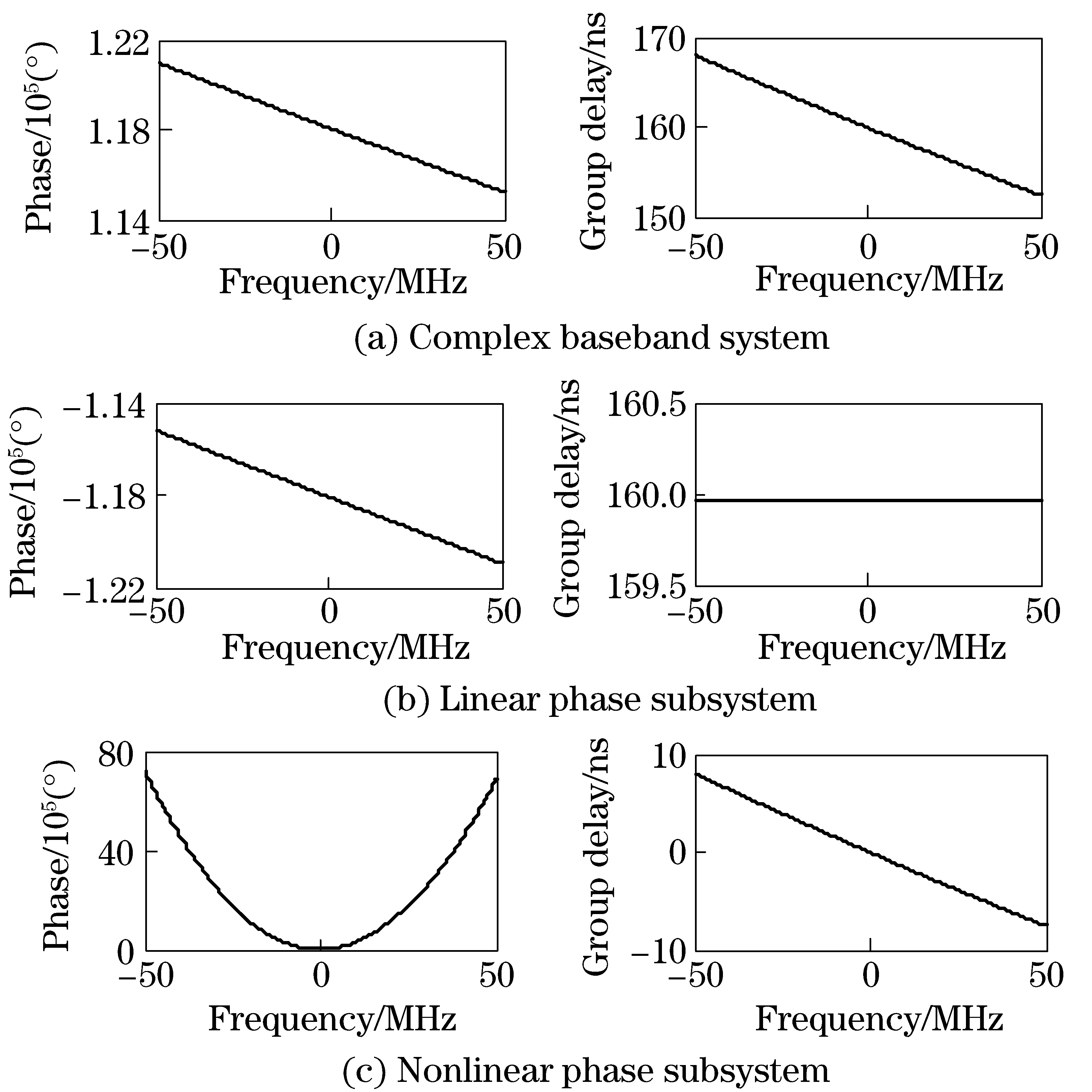
Fig.3 Phase and group delay decomposing of the system Hiob(ω)
The linear phase subsystemHL(ω) is approximated by the combination of the integer-interval delay and the Lagrange-type fractional delay filter, and the approximation errors in terms of the magnitude, phase, and group delay have been illustrated in Fig.4. In this simulation, the integer-interval delay is 63 samples and the fractional delay is about 0.987 7 samples. The integer-interval delay was assumed to be approximated with zero error, and the order of the Lagrange-type fraction delay filter was 3. It can be seen from the figure that the approximation errors achieve the minimum atω0=0 and degrade as frequency increases. However, the maximum magnitude, phase, and group delay errors in the frequency range of -50 MHz to 50 MHz will not exceed 0.004 dB, 0.01° and 2 ps, respectively.
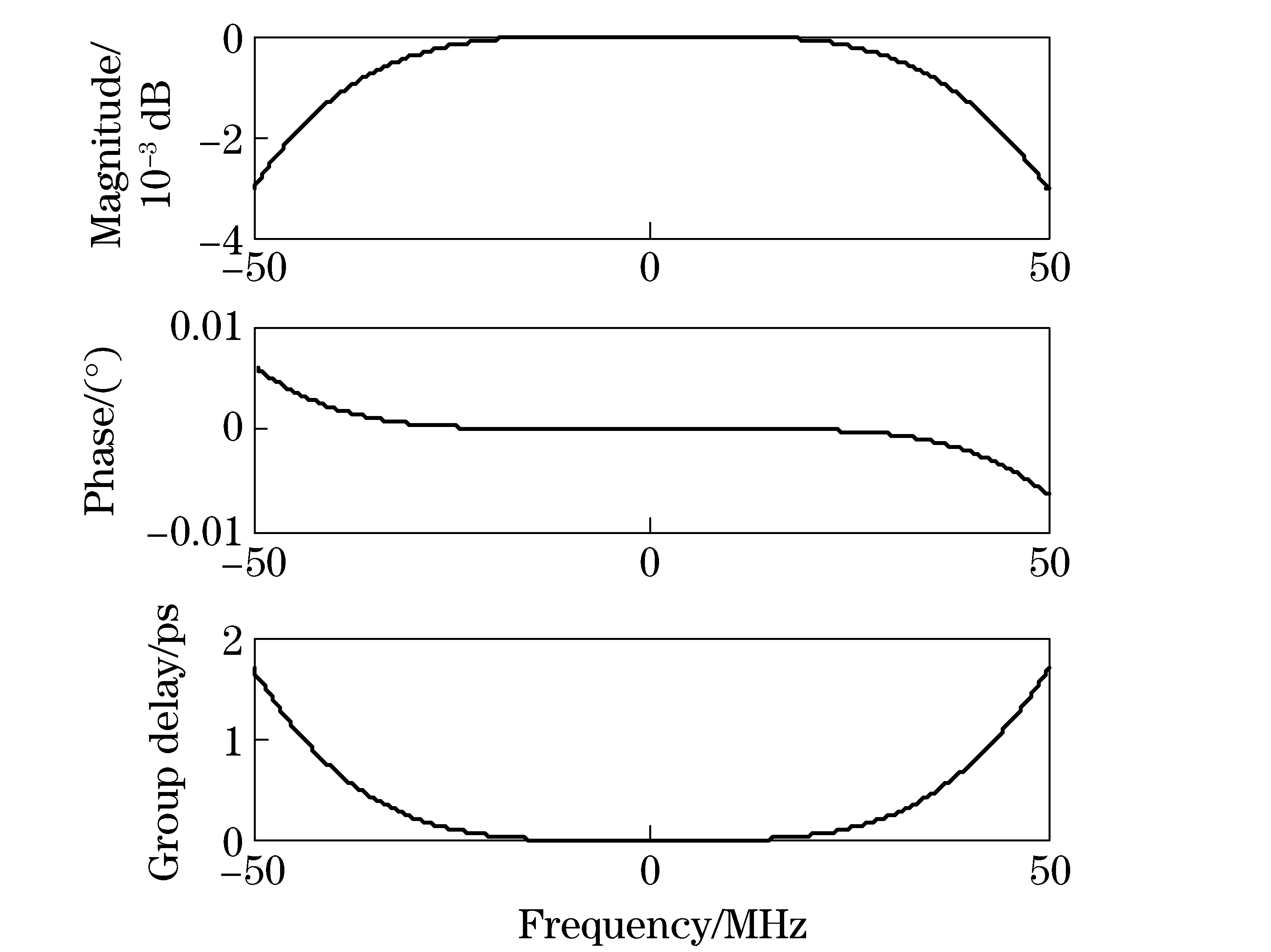
Fig.4 Approximation errors of the linear phase subsystem
The nonlinear phase subsystemHnL(ω) is approximated by the complex-coefficient FIR filter that is based on the frequency-domain weighted least square method. Fig.5 illustrates the approximation errors of the subsystemHnL(ω) where the filter order was 21 and the frequency resolution was 0.1 MHz. For the nonlinear phase subsystem, the quasi-symmetry characteristic of the phase response is very important because such characteristic makes the subsystem be accurately approximated with lower filter orders. In our simulation, the magnitude, phase and group delay errors are less than 0.004 dB, 0.01° and 8 ps, respectively.
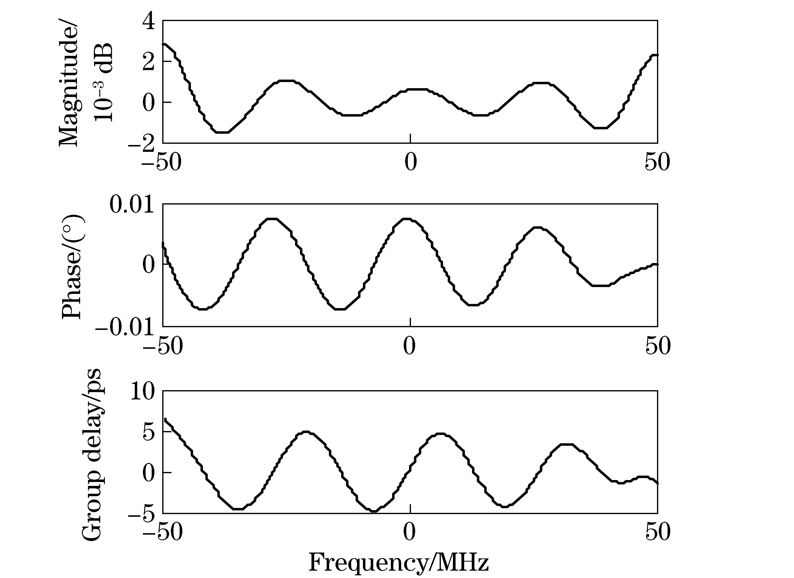
Fig.5 Approximation errors of the nonlinear phase subsystem
Fig.6 illustrates the total errors of our proposed ionospheric dispersion simulation method by summing the approximation errors of each subsystem. It can be summarized from the simulations that the method simulates ionospheric dispersion with a magnitude error not exceeding 0.003 dB, a phase error not exceeding 0.01°, and a group delay error not exceeding 10 ps. However, only a 3-order Lagrange-type fractional delay filter and a 21-order FIR filter are introduced. This means that our method has the ability to accurately capture the ionospheric dispersion characteristics, as well as to simply implement them.

Fig.6 Total errors of the ionospheric dispersion simulation
4 Conclusion
In this paper, we have presented a generalized ionospheric dispersion simulation method to test wideband satellite-ground-link radio systems for dispersion robustness. Comparing with conventional methods, we model the dispersive effects on radio waves as an allpass nonlinear phase system, and hence, the method can simulate ionospheric dispersion without knowing any signal priori information. To improve the simulation accuracy and reduce the implementation complexity, the system is decomposed into three allpass subsystems and the design methods are given briefly. Using simulations, we show that our proposed method has the ability to accurately simulate the nonlinear advanced phase and the additive group delay introduced by ionospheric dispersion with a low implementation complexity.
[1] Liu J, Kuga Y, Ishimaru A, et al. Ionospheric effects on SAR imaging: a numerical study [J]. IEEE Transactions on Geoscience and Remote Sensing, 2004, 41(5): 939-946.
[2] Humphreys T E, Psiaki M L, Kintner P M. Modeling the effects of ionospheric scintillation on GPS carrier phase tracking [J]. IEEE Transactions on Aerospace and Electronic System, 2010, 46(4): 1624-1637.
[3] Li S Y, Liu C H. Modeling the effects of ionospheric scintillations on LEO satellite communications [J]. IEEE Communications Letters, 2004, 8(3): 147-149.
[4] Zhao Junxiang, Chang Qing, Zhang Qishan, et al. Research of ionospheric time-delay error simulation in high dynamic GPS signal simulator [J]. Chinese Journal of Aeronautics, 2003, 16(3):169-176.
[5] Wang Jun, Xi Xiaoli, Liu Jiangfan. The design of GPS IF signal software simulator [C]∥Proceedings of the 2010 International Symposium on Signals, Systems and Electronics. Piscataway: Institute of Electrical and Electronics Engineers Inc, 2010:1-3.
[6] Hu Yan, Li Hong, Lu Mingquan. Design and implementation of a high fidelity GLONASS signal simulator [C] ∥Proceedings of 2012 Spring World Congress on Engineering and Technology. Washington: IEEE Computer Society, 2012:1-3.
[7] Humphreys T E, Psiaki M L, et al. Simulating ionosphere-induced scintillation for testing GPS receiver phase tracking loops [J]. IEEE Journal of Selected Topics in Signal Processing, 2009, 3(4):707-715.
[8] Conker R S, El-Arini M B, Hegarty C J, et al. Modeling the effects of ionospheric scintillation on GPS/satellite-based augmentation System availability [J]. Radio Science, 2003, 48(1): 688-693.
[9] Lawrence R S, Little C G, Chivers H J A. A Survey of ionospheric effects upon earth-space radio propagation [J]. Proceedings of the IEEE, 1964, 52(1):4-27.
[10] Deng T B. Coefficient-symmetries for implementing arbitrary-order Lagrange-type variable fractional delay digital filters [J]. IEEE Transactions on Signal Processing, 2007, 55(8): 4078-4090.
[11] Pei S C, Shyu J J. Design of arbitrary complex coefficient FIR digital filters by complex weighted least squares approximation [J]. IEEE Transactions on Circuits and Systems-Ⅱ, 1994, 41(12):817-820.
(Edited by Cai Jianying)
10.15918/j.jbit1004-0579.201524.0413
TN 955 Document code: A Article ID: 1004- 0579(2015)04- 0513- 06
Received 2014- 04- 21
Supported by the Foundation of Shanghai Aerospace Science and Technology (20120541088); China Postdoctoral Science Foundation (2015M580997)
E-mail: zhengzhebit@bit.edu.cn
猜你喜欢
杂志排行

Journal of Beijing Institute of Technology的其它文章
- Influence of shear sensitivities of steel projectiles on their ballistic performances
- Multi-subpulse process of large time-bandwidth product chirp signal
- Factor-graph-based iterative channel estimation and signal detection algorithm over time-varying frequency-selective fading channels
- Nano-silica particles enhanced adsorption and recognition of lysozyme on imprinted polymers gels
- Similarity matrix-based K-means algorithm for text clustering
- Optimizing control of a two-span rotor system with magnetorheological fluid dampers