Multi-subpulse process of large time-bandwidth product chirp signal
2015-04-22ZHANGHonggang张洪纲FANHuayu范花玉HEShaohua何少华LIUQuanhua刘泉华
ZHANG Hong-gang(张洪纲), FAN Hua-yu(范花玉), HE Shao-hua(何少华), LIU Quan-hua(刘泉华)
(School of Information and Electronics, Beijing Institute of Technology, Beijing 100081, China)
Multi-subpulse process of large time-bandwidth product chirp signal
ZHANG Hong-gang(张洪纲), FAN Hua-yu(范花玉), HE Shao-hua(何少华), LIU Quan-hua(刘泉华)
(School of Information and Electronics, Beijing Institute of Technology, Beijing 100081, China)
To prevent the long-time coherent integration and limited range window stumbling blocks of stretch processing and reduce computational complexity, a novel method called multi-subpulse process of large time-bandwidth product linear frequency modulating (LFM) signal (i.e. chirp) is proposed in this paper. The wideband chirp signal is split up into several compressed subpulses. Then the fast Fourier transform (FFT) is used to reconstruct the high resolution range profile (HRRP) in a relative short computation time. For multi-frame, pulse Doppler (PD) process is performed to obtain the two-dimension range-Doppler (R-D) high resolution profile. Simulations and field experimental results show that the proposed method can provide high-quality target profile over a large range window in a short computation time and has the promising potential for long-time coherent integration.
multi-subpulse process; large time-bandwidth product; chirp signal; computational complexity; coherent integration
In order to achieve high range resolution, radar transmits wideband pulses; while to get high signal-to-noise ratio (SNR), it is desirable to increase the pulsewidth. Pulse compression is a method which combines the high energy of a long pulsewidth with high range resolution. Among the various large time-bandwidth product signals, chirp signal is a popular choice. There are two commonly used pulse compression techniques for chirp signal: matched filter processing and stretch processing[1].
The digital matched filter processing requires a sampling rate of at least twice the signal bandwidth according to the Nyquist sampling theorem. When radar transmits wideband chirp signals, ittypically requires an extremely high sampling rate for the analog-to-digital (A/D) converter, which increases the computational burden of real-time digital signal processing. Thus the matched filter processing is predominantly used for narrowband radar. To overcome this problem, the stretch processor is normally used in the extremely wide bandwidth chirp signal[2]. The sampling rate of this technique can be reduced significantly. The two methods have been compared and fully discussed in Refs.[3-5]. The stretch processing has two major disadvantages. It can only yield the high range resolution profile over a limited range window and long-time coherent integration is unachievable, which leads to the degradation of image quality and the failure of measuring the Doppler and micro-Doppler[6].
Another method to process the wide bandwidth chirp signal is presented in Refs.[7-9] where pulse compression is performed in the subband domain. This method can decrease the sampling rate and reduce the processing time. However, it still has trouble in long-time coherent integration, especially for high speed targets.
Inspired by the concept of using multi-frame stepped frequency signals to achieve long-time coherent integration[10-13], we proposed a multi-subpulse processing method for large time-bandwidth product chirp signal. It can not only decrease the computational complexity effectively, but also achieve coherent integration simultaneously for the wideband signal. To the best of the authors’ knowledge, this method has never been reported.
1 Multi-subpulse process
1.1 Basic concept
The intermediate frequency (IF) chirp pulse can be expressed as
(1)
where

(2)
and wheretrepresents time,Tpdenotes the pulsewidth,fIis the intermediate frequency, andkis the chirp slope. The bandwidth is determined byB=kTp. To get high SNR and high range resolution, the signal should have a large time-bandwidth productD=BTp.
The multi-subpulse processing method first averagely splits up chirp signal intoNsubpulses, whereNis an integer, as shown in Fig.1. The resulting subpulses are still chirp signals whose pulsewidth is denoted byT0=Tp/Nand bandwidth is determined byB0=Δf=B/N, where Δfis the frequency division interval.
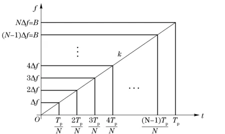
Fig.1 Division of large time-bandwidth product chirp signal in time-frequency domain
1.2 Choice of division numberN
The division numberNis properly chosen to meet the condition that time-bandwidth product of the subpulse should be much greater than one, i.e.B0T0≫1. Thus the frequency spectrum of the subpulse is approximately close to rectangle so that pulse compression can be applied.
The proposed division presented here is performed simultaneously inNchannels by firstly mixing with different phase detectors and then passing through lowpass filters. The phase detectors in different channels can be written as
(3)
wherendenotes thenth subpulse.
After mixing with the phase detectors and lowpass filtering, we have
(4)
From Eq.(4), it is obvious that each subpulse has a pulse duration ofT0and has a bandwidth ofB0=kT0. TheNsubpulses become the stepped frequency like signal whose frequency stepping interval Δfis the single subpulse bandwidthB0. To make the two types of signals equivalent, the initial phase of theNsubpulses must be linear, that is to say, the adjacent two subpulses should have a constant phase difference.
From Eq.(4), the phase of each subpulsecan be represented as
(5)
Its start frequency is -B/2+nB/Nand the bandwidth is determined byB0=B/N. The initial phase of each subpulse isφn(tn) whentn=-T/2+nT/N.
The phase difference betweenφn(tn) andφn+1(tn+1) can be calculated as
(6)
It contains two parts: the constant phase and the varying phase. The varying phase is rewritten as
(7)
Apparently, to ensure the two adjacent subpulses have a constant phase difference, 3BT/N2in the varying partφ(n) which prevents the phase of adjacent subpulses being constant should be an integer. Thereforeφ(n) will be an integer multiple of 2π. Under such condition, multi-subpulse process can be applied.
1.3 Multi-subpulse process of chirp
According to the aforementioned principal, subpulse numberNis properly chosen. Then multi-subpulse process can be performed for the large time-bandwidth product chirp signal. The flow chart of the processing is demonstrated in Fig.2.

Fig.2 Flow chart of multi-subpulse process of large time-bandwidth product chirp signal
As shown in Fig. 2, the intermediate frequency chirp signal is assigned intoNchannels. In each channel, the signal will firstly pass through the phase detectors, whose expression is given in Eq.(3). Then the frequency-shifted signals must be lowpass-filtered so that the large time-bandwidth product chirp signal can be divided up intoNsubpulses inNdifferent channels. To process the signal completely in the digital domain, the A/D converter and digital IQ processor are employed. Since each subpulse is a complex chirp signal whose time durance isT0and bandwidth isB0, the sampling rate of A/D converter can be dramatically decreased to 1/Nof the direct sampling case.
To improve the SNR, pulse compression is performed to each subpulse using the matched filter processing. Meanwhile, the phase influence caused by the Doppler must be compensated so that the pulse train can be integrated coherently. Since the original chirp is a wideband signal, it cannot compensate the phase by using the uniform compensation coefficient. However, it is much easier for the subpulses to compensate the phase by using different coefficients in different frequency channels, because these subpulses are narrowband signals.
Assuming the target moves towards radar in a constant velocityv, and it locates at an initial radial range ofR0. The IF chirp can be rewritten as
(8)
wherecis speed of light,fcis the carrier frequency,Ris determined by
R=R0-mvTr,m=0,1,…,M-1
(9)
wheremis the pulse or frame number, andTris the pulse repetition interval.
When the envelope movement of the totalMframe is less than half of the pulsewidth after compression, which is
(10)
The envelope movement can be ignored. From Eq.(10), we have
v (11) It shows that the long coherent integration time requires that the target must have a limited velocity. Furthermore, with the bandwidth of the subpulse increase, the velocity limit gets stricter. Similarly, the target’s velocity will influence the phase. To get rid of these effects caused by the target’s motion, compensation must be applied for each subpulse. The first compensation coefficient which is applied in subpulse compression step eliminates the waveform dispersion caused by the target’s motion. That is p1(t)=exp(-j4πkvct2/c) (12) wherevcis the cued velocity which is provided by radar tracking. The second compensation coefficient is (13) wheref0=fc-B/2 is the start frequency. The first term compensates the frame influence, and the second term compensates the subpulse influence. Note that it is a predominant advantage for these subpulses to compensate the velocity influence, because each subpulse can be compensated at each frequency channel respectively. Hence, it makes the long-time coherent integration feasible. After the velocity compensation, PD process can be done for the same frequency subpulses in different frames by using FFT. This approach can distinguish targets from different velocities. Finally, we collect the data from same Doppler bins and obtain the high range resolution profile over a large range window by using inverse FFT (IFFT). This step is similar with the process of stepped frequency signal and it avoids the large range window problem in stretch processing. Then the two-dimension R-D high resolution profile can be obtained. The following constant false alarm detection is performed, and it results in the accurate range and velocity measurements of the detected target. 1.4 Performance of proposed method Here we illustrate the performance of the proposed method and three methods in the literatures: the matched filter processor, the stretch processor and the subband pulse compression processor. Assume the chirp signal has a large time-bandwidth product, the comparisons are listed in Tab.1. Tab.1 Difference of the four methods From Tab.1, we can see that multi-subpulse process requires a sampling rate of 2B/N, which is greatly reduced compared to the matched filter processor. Since the original chirp is divided intoNsubpulses,Nparallel channels can be processed simultaneously. Thus the computation time decreases sharply. Moreover, the subpulse process makes motion compensation at different frequencies possible. And it obtains HRRP over a large range window unlike the stretch processing. The most significant benefit is that the proposed method can realize long-time coherent integration for high speed target. 2.1 Simulations In order to validate the correctness of the proposed method, simulations are performed. Suppose theXband chirp has a pulsewidth of 20 μs and its bandwidth is 1 GHz. The time repetition interval is 100 μs. According to the principal of choosing subpulse number, the number is set to 20. Thus the pulse duration of subpulse is 1 μs and the bandwidth is 50 MHz. The sampling rate is 100 MHz. Assuming the target locates at a distance of 265 m relative to the range window, its velocity is 400 m/s and the cued velocity is 370 m/s. The SNR level of original signal is -20 dB. According to the parameter listed above, the maximum unambiguous range is 3 m, the maximum unambiguous velocity is 150 m/s. And the maximum velocity with which the envelope movement can be neglected is 937.5 m/s. It is much larger than the target speed in our scene. The one-dimension HRRP of matched filter processor and multi-subpulse process are plotted in Fig.3. Fig.3 One-dimension HRRP using matched filter and multi-subpulse process From Fig.3, it can be seen that the multi-subpulse process approximately has the same performance with matched filter processor. Their HRRPs almost have the same peak side lobe ratio (PSLR) and the same mainbeam width. However, the latter method requires much smaller sampling rate and much shorter computation time. The two-dimension high resolution profiles using matched filter processor and multi-subpulse process are presented respectively in Fig.4. The integration pulse number is 16. We can evidently see that multi-subpulse process of the large time-bandwidth product chirp signal can integrate the pulses coherently in spite of the high speed motion of target. In contrast,the matched filter processor fails to integrate coherently. Therefore the R-D profile disperses due to the high speed motion. Fig.4 Two-dimension R-D high resolution profile of matched filter and multi-subpulse process 2.2 Field experiments To further prove the feasibility of the proposed method, field experiments are carried out. The original chirp signal operates atXband with pulsewidth of 200 μs and bandwidth of 1 GHz. The subpulse number is chosen as 20. Fig.5a is the HRRP of a civil airplane using matched filter processor while Fig.5b using the multi-subpulse process. Note that thex-axis just indicates the relative range but not the absolute range. Comparing the two HRRPs, they are almost the same except that the HRRP after multi-subpulse process contains grating lobes with a level of -25 dB. And eliminating the grating lobes will be our major work in the following research. Fig.5 HRRP of civil airplane using matched filter and multi-subpulse process We have proposed a method called multi-subpulse process for the large time-bandwidth product chirp signal. The proposed method compresses the original chirp signal with a relatively low sampling rate so that the computation time can be decreased significantly. It also circumvents the large range window problem in stretch processing. More importantly, pulses can be integrated coherently in a long time using the proposed method. To verify the feasibility of the presented method, simulations and field experiments have been performed and promising results have been achieved. Hence, the presented novel method provides a well performed solution to the real time and coherent integration problem of wideband chirp signal. [1] Mahafza B M, Elsherbeni A Z. MATLAB simulations for radar systems design[M]. Florida: CRC Press, 2004. [2] Caputi W J. Stretch: a time-transformation technique[J]. IEEE Transactions on Aerospace and Electronic System, 1971, 7(2): 269-278. [3] Middleton R J C. Dechirp-on-receive linearly frequency modulated radar as a matched-filter detector[J]. IEEE Transactions on Aerospace and Electronic Systems, 2012, 3(3): 2716-2718. [4] Long T, Wang Y, Zeng T. Signal-to-noise ratio in stretch processing[J]. Electronics Letters, 2010, 46(10): 720-721. [5] Wang Jun, Cai Duoduo, Wen Yaya. Comparison of matched filter and dechirp processing used in Linear Frequency Modulation[C]∥International Conference on Computing, Control and Industrial Engineering, Piscataway, NJ, USA, 2011. [6] Zhu Fengbo, Yang Wenjun, Deng Zhenmiao. A study on coherent wideband phased-array radar systems based on dechirp processing[J]. Modern Radar, 2011, 33(2): 42-46. (in Chinese) [7] Rabinkin D, Truong N. Optimum subband filterbank design for radar array signal processing with pulse compression[C]∥the 2000 IEEE Sensor Array and Multichannel Signal Processing Workshop, Piscataway, NJ, USA, 2000. [8] Fu Wei, Li Ming, Liu Fang. A radar wideband receiving method based on subband pulse compression[J]. Fire Control Radar Technology, 2010, 39(4): 47-51. (in Chinese) [9] Shui Penglang, Bao Zheng. A pulse compression method of UWB radar based on intersection of frequency spectrum[J]. Acta Electronica Sinica, 1999, 27(6): 50-53. (in Chinese) [10] Yuan Haojuan, Gao Meiguo. Signal processing of mutli-frame stepped frequency radar based on keystone transform[J]. Transaction of Beijing Institute of Technology, 2008, 28(11): 1023-1026. (in Chinese) [11] Liu Haibo, Lu Jundao. Target motion compensation algorithm based on keystone transform for wideband pulse Doppler radar[J]. Transaction of Beijing Institute of Technology, 2012, 32(6): 625-630. (in Chinese) [12] Liu Haibo, Zhao Xiaona, Lü Huihui. Parameter design of stepped frequency waveform and its signal processing algorithm in cluter[J]. Transaction of Beijing Institute of Technology, 2013, 33(6): 638-643. (in Chinese) [13] Yuan Haojuan, Gao Meiguo, Mu Jianchao. Multi-frame stepped frequency signal processing based on Doppler bin alignment[J]. Journal of Electronics & Information Technology,2009, 31(7): 1659-1663. (in Chinese) (Edited by Cai Jianying) 10.15918/j.jbit1004-0579.201524.0411 TN 957.51 Document code: A Article ID: 1004- 0579(2015)04- 0501- 07 Received 2014- 02- 09 Supported by the National Natural Science Foundation of China (61301189) E-mail: liuquanhua@bit.edu.cn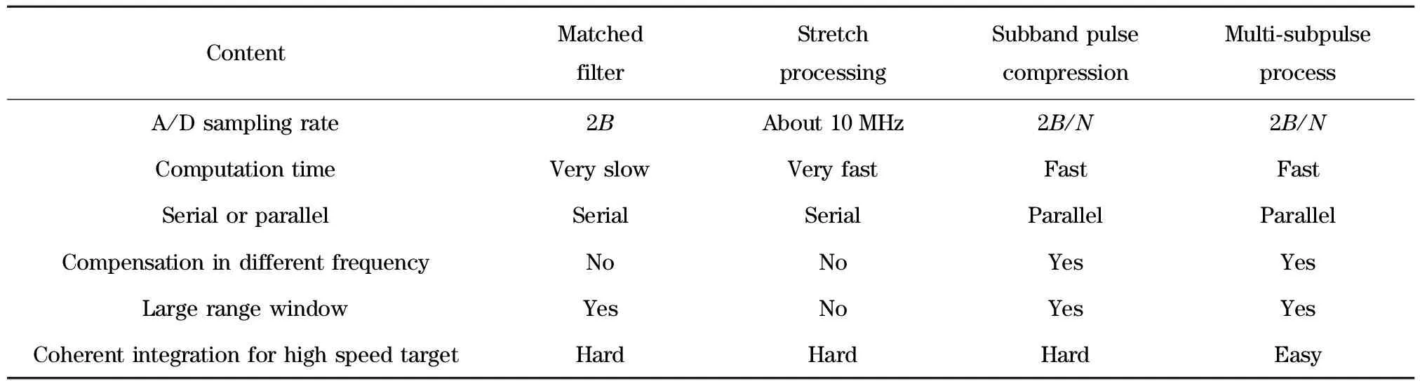
2 Simulations and field experiments


3 Conclusion
杂志排行

Journal of Beijing Institute of Technology的其它文章
- Influence of shear sensitivities of steel projectiles on their ballistic performances
- Generalized ionospheric dispersion simulation method for wideband satellite-ground-link radio systems
- Factor-graph-based iterative channel estimation and signal detection algorithm over time-varying frequency-selective fading channels
- Nano-silica particles enhanced adsorption and recognition of lysozyme on imprinted polymers gels
- Similarity matrix-based K-means algorithm for text clustering
- Optimizing control of a two-span rotor system with magnetorheological fluid dampers