Synergetic Analysis and Possible Control of Vortex-Induced Vibrations in a Fluid-Conveying Steel Catenary Riser
2015-04-05MENGDanandZHUChongji
MENG Dan, and ZHU Chongji
1)School of Architectural Engineering,Qingdao Agricultural University,Qingdao266033,P. R. China
2)School of Civil Engineering and Architectural,University of Jinan,Jinan250022,P. R. China
Synergetic Analysis and Possible Control of Vortex-Induced Vibrations in a Fluid-Conveying Steel Catenary Riser
MENG Dan1),*, and ZHU Chongji2)
1)School of Architectural Engineering,Qingdao Agricultural University,Qingdao266033,P. R. China
2)School of Civil Engineering and Architectural,University of Jinan,Jinan250022,P. R. China
This work aimed to demonstrate possibilities for both active and passive control of the vortex-induced vibration and fatigue life of steel catenary risers via an analysis of the self-organization and evolution of the structural vibration based on synergetic theory. An analysis of the complex interrelated and synergistic relationship between the order parameter and the fast variable was performed, and the master equation of the nodal displacements was established as the order parameter for the evolution of the riser’s structural vibration. Passive control methods include modifying the structure’s elastic modulus, the internal fluid velocity, the top tension and the structural damping ratio, while an active control involves adjusting the external flow rate. Optimized parameters were obtained by analyzing the non-steady state solution of the master equation. The results show that the fatigue life greatly increases as the riser’s elastic modulus decreases. In contrast, the fatigue life decreases with an increase of the internal fluid velocity. With an increase of the top tension, the vibration amplitudes and the number of modes may decrease, resulting in fewer bending stress cycles and a longer fatigue life. Furthermore, the structural damping ratio should be as large as possible. Finally, an active and passive control of the riser structure’s response to vortex-induced vibration and its fatigue life can be achieved by carefully modifying the parameters mentioned above. The results may provide a theoretical framework for engineering practice concerning the design and control of steel catenary riser structures which are affected by vortex-induced vibration.
steel catenary riser; vortex-induced vibration; synergetics; vibration control
1 Introduction
As a cable-like structure, steel catenary risers (SCRs) are widely used in offshore installations. Since they offer both a promising technological and commercial solution, SCRs have become primary candidates for a future application on floating production platforms in the ultradeepwater oil and gas industry.
Several papers have been published focusing on slender risers. For instance, Chucheepsakulet al.(2003) investigated the effect of the transported mass on the riser equilibrium configuration for large displacements in the cases of specified top tensions and a specified arc-length. Kaewunruenet al. (2005) studied the influence of several marine riser parameters,e.g., the flexural rigidity, top tension, internal flow velocity and static offset, on the nonlinear free vibration behavior by reformulating the governing equation as an eigenvalue problem. Kuiperet al.(2008) investigated the parametric excitation stability of a deepwater riser utilizing a numerical time-domain technique, while Changet al.(2008) studied the dynamicresponse of deepwater drilling risers subjected to random waves and vessel motions, and concluded that the vessel motion, rather than the wave force, produces the principal dynamic loading in the nonlinear dynamic response of the risers. Bahmani and Akbari (2010) studied the dynamic response and vortex shedding for an elastically mounted circular cylinder in the case of laminar flow. They showed that a decrease in either the mass ratio or the damping ratio of the system can lead to an increase in both the oscillation amplitude and the reduced velocity range over which the lock-in occurs. Menget al. (2011), and Meng and Chen (2012) showed that the natural frequencies of the risers are only slightly reduced when applying a low internal fluid flow rate but significantly reduced when applying a very high fluid flow rate.
One of the key issues in the analysis and design of SCRs exposed to ocean currents is to estimate and control the fatigue damage caused by vortex-induced vibration (VIV). A simplified procedure suitable for assessing the fatigue life of flexible risers during the early stages of design was proposed by Martins and Pesce (2002). Guoet al. (2005, 2008) analyzed the effect of an internal flowing fluid on the fatigue life of a short rigid riser. Their results showed that, when the natural frequency of the riser is close to the vortex shedding frequency, theresponse of the VIV will increase and the fatigue life of the riser will decrease considerably due to the change of the initial velocity. The relative contribution of in-line (IL) and cross-flow (CF) vibrations to fatigue damage was calculated directly from the measured data obtained by large-scale tensioned steel riser model tests by Baarholmet al. (2006). They found that IL stresses are the main cause of VIV fatigue for tension-dominated risers, while CF stresses are the main cause of fatigue for bendingstiffness-controlled risers. Xiaet al. (2008) performed a parametric study on an SCR connected to a semi- submersible to identify factors that mainly influence its loading condition and fatigue life, and proposed several weight-optimized configurations. Field data gathered on the multimodal vibration of a long flexible riser was used by Iranpouret al. (2008) to conduct a series of experimental tests in order to estimate the fatigue life of risers. The experimental results indicated that higher harmonics significantly contribute to fatigue damage and cannot be ignored.
Liet al. (2010) analyzed the fatigue life of top tensioned risers subjected to VIVs as well as the influence of certain parameters,e.g., the flexural rigidity, top tension and internal flow velocity, on the fatigue life of the riser. Guet al. (2013) studied the nonlinear coupled dynamics of the in-line and cross-flow VIVs of a long tensiondominated riser by adopting the wake oscillator model and considering the variation of the mean top tension.
As a multi-level and complex multi-degree-of-freedom domain system consisting of many sub-structures, a marine riser structure is always subject to an exchange of matter and energy with the external environment. The interaction between its internal subsystems is nonlinear in the presence of structural vibrations, which not only includes the material’s physical nonlinearity, but also the geometric nonlinearity caused by the structural deformation and the nonlinear coupling between the various substructures (Haken, 1983). Synergetic analysis is a powerful tool for investigating the nonlinear coupling of subsystems during the evolution of the system. It allows to examine the interaction between the subsystems that eventually results in the system’s macro-structure with respect to space, time, or the system’s function. Concerning VIVs of the riser, if the external forces acting on the structure (including the externally applied force and the artificially imposed control) are considered as intrinsic system fluctuations, the structure itself can be considered as an autonomous system, and the evolution of the system as a self-organization problem (e.g., Knyazeva and Kurdyumov, 1994).
Therefore, in this work, we aimed to 1) conduct a preliminary study on the evolution of VIVs of SCRs utilizing synergetic analysis and derive a viable structure control method, and 2) analyze the nonlinear VIVs of the riser in the time domain, and investigate possibilities for a passive or an active structural vibration control by manipulating the elastic modulus, internal fluid velocity, top tension and structural damping ratio, or the external flow velocity, respectively.
2 The Geometrically Nonlinear Equations of Riser Motion
2.1 Riser Deformation
With reference to the global Cartesian coordinate system, a general 3D continuum model of an SCR connecting a stationary floating structure to the seabed with simple pinned-pinned supports is shown in Fig.1. The horizontal offsetyVand the water depthxHdefine the chord inclination angle of the riser (i.e.,θr=tan-1xH/yV). In the marine environment, only the specified time independent loading (i.e., the force of gravity, static currents and the centrifugal force caused by the transported fluid) is considered. The riser can be considered as a single catenary configuration with the unstretched state as the initial condition. Due to the extensibility of the riser, the unstretched state translates to the equilibrium state, which is considered as an initial state of the riser. Subsequently, due to disturbances, such as waves, time dependent currents, and internal fluid flows, the riser is eventually displaced to the third state,i.e., the displaced state (Fig.1). In this state,u1is the vertical displacement, andu2andu3denote the horizontal displacement in the XY plane and the XZ plane, respectively. The strain at any material point of the riser is zero in the unstretched state, which is equal toε0andεin the equilibrium and the displaced state, respectively. The incoming constant and uniform external flow with densityρeand normal velocityUis considered to be parallel to theY-direction and therefore also parallel to the SCR plane (XY-plane) of the initial equilibrium curvatures.
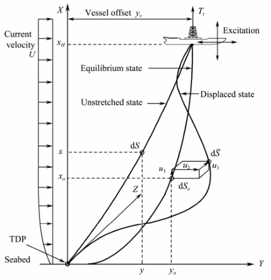
Fig.1 Schematic illustration of the large deformation of an SCR conveying a fluid.
2.2 Governing Equation of Motion
The transverse displacement of the riser can then becalculated as follows (Meng and Chen, 2012):

Following the standard procedure of the Galerkin finite element method, the coupled fluid-structure dynamical system described by Eq. (1) can be written in matrix form as

where [N]=[N1N2N3N4], {d}=[u1,3u'1,3u2,3u'2,3], andNiwithi=1, 2, 3, 4 represent the cubic polynomial shape functions, andui,3withi=1, 2 the nodal degree of freedom. In Eq. (2),

is the external force matrix;

is the total mass matrix; and {D},{D˙}, and {D˙˙} denote the global displacement, the velocity and the acceleration in cross-flow direction, respectively;

is the total gyroscopic matrix and
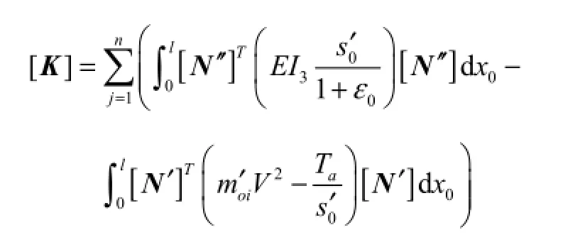
the total stiffness matrix.
3 Synergetic Analysis of the Coupled Dynamical System
3.1 Master Equation for the Order Parameter Evolution
If a process is carried out very fast, so that it is almost impossible to exchange energy with the surroundings, then this process can be regarded as an adiabatic process in accordance with the thermodynamic point of view. The adiabatic elimination principle allows to eliminate changes of the fast relaxation parameter inside the system while retaining the changes of the slow relaxation parameter.


The attenuation of the state variablex1is, and the attenuation of the state variablex2isThe relaxation time of the state variablex1is much longer than the relaxation time of the state variablex2. The adiabatic elimination principle allows to omit small changes of the relaxation time and large variations of the state variablex2,i.e., dx2/dt=0. Then, Eq. (4) can be rewritten as:

Substituting Eq. (5) into Eq. (3) yields

Eq. (6) is the master equation for the order parameterx1of the SCR system subjected to vibrations.
3.2 Analysis of the Non-Steady State Solution
The non-steady state solution of the differential equation in Eq. (6) is

whereC1is a constant that is determined by the initial state of the system.
The structure of the non-steady state solution implies that, in cases without fluctuation ([R]=0), the state parameterx1of the system vibration exhibits an exponential decreasing trend over time since -[K]/[C]〈0, whereas in the case of fluctuations ([R]≠0), the value of the state pa-rameter depends on the history of the fluctuations.
When considering the synthesis of the control force and the external force as structural fluctuation, the structure control can be achieved as follows:
1) To accelerate the change of the state variablex1, a decrease of the rate of increase over time or a decrease of its value can be achieved by adjusting the stiffness [K] or the damping coefficient [C] of the structure, which corresponds to a passive control of the structure.
2) Without changing the characteristics of the structure itself, the integrator value of Eq. (7) can be forced to converge to zero at any time by adjusting the external forces, which corresponds to an active control of the structure.
3) A combination of the two extreme cases,i.e., changing both the characteristics of the structure and the external forces at the same time, corresponds to a hybrid control of the structure.
4 Vortex-Induced Vibration Control Analysis
To determine the dynamic response of the riser, the numerical direct integration method was employed in this study, and the Newmark integration method was found to be suitable for solving this problem.andwere used as integration constants, andu3bottom=u3top=0 as boundary condition at both ends of the riser. The initial conditions for determining the dynamic responses of the marine risers can be expressed as. The time step Δtused in all calculations was chosen to be much smaller than the critical time step, and its effect on the results was investigated. A conveying fluid and top pretension were assumed for the analytical model used in this work to account for the inertial force of the mass of the internal fluid and the strain caused by the large extensibility of the SCR. The parameters for the model are listed in Table 1.
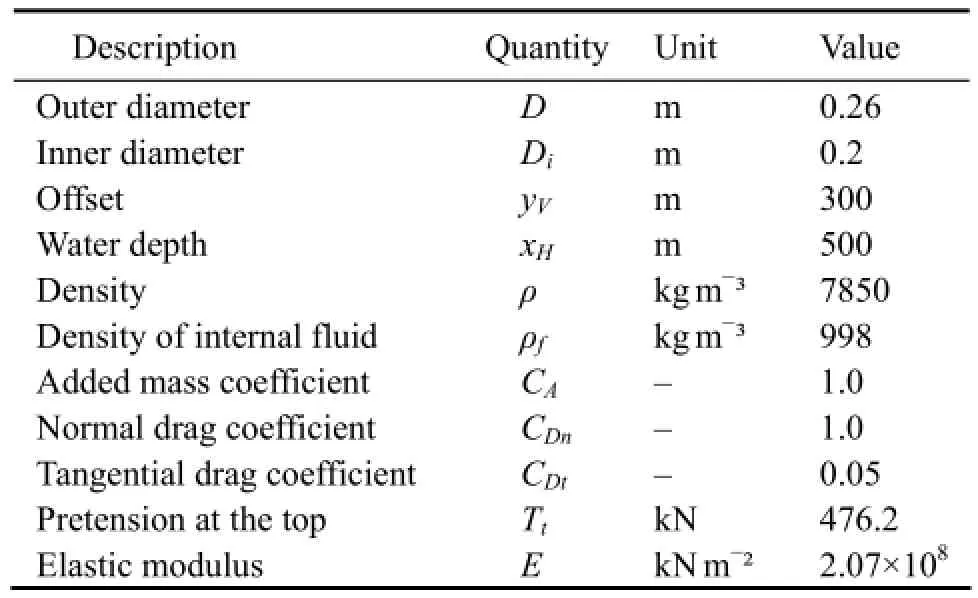
Table 1 Model parameters
4.1 Passive Structural Vibration Control
4.1.1 Effect of the elastic modulus on the dynamic response
The ability of the wake oscillator model to predict the effect of VIVs has been addressed in the previous section. Here, the focus lies on evaluating the capability of the same model to predict the shape of the slender structures under the influence of other parameters,e.g., the elastic modulus, the internal fluid velocity, the top pretension and the structural damping ratio.
The external flow velocity was set to 0.3 m s-1, and the variation of the cross-flow displacement amplitudes as a function of the elastic modulus is shown in Fig.2. The corresponding power spectrum densities (PSDs) of the riser at the locationsxH/4 andxH/2 from the bottom of the riser and the long-term bending stress responses are shown in Figs.3 and 4, respectively.
For an elastic modulus of 0.5E, the amplitude is dominated by mode 9 and the vibration frequencies at the two locations are 0.22 Hz and 0.22 Hz, respectively, which correspond to the vortex shedding frequencies for which the lock-in phenomena occur. At the same time, a mode transition occurs and the dynamic response amplitude increases with the elastic modulus. For an elastic modulus of 1.0E, the amplitude is dominated by mode 7 and the vibration frequencies at the two locations are both 0.184 Hz. But when the elastic modulus is increased to 1.5Eand the number of excited modes is kept constant, the riser response displacement amplitude decreases and the vibration frequencies both change to 0.2 Hz. Obviously, the flexural rigidityEIplays a significant role in the natural frequency domain. The small figures ofE, corresponding to a low flexural rigidity, indicate that the natural frequency is of the softening type. However, the higher ranges demonstrate the hardening dynamic characteristic of the riser, similar to the characteristic observed for flexural members,e.g., beams, girders, and plates.
The time histories of bending stress at the locationsxH/4 andxH/2 are shown in Fig.4. In this figure, the three curves represent the time-stress curves for different values of the elastic modulus. It can be seen that, after some transient dynamics, the cross-flow VIV response reaches the steady-state or ‘limit cycle’, with a slight phase difference between the time series, depending on the elastic modulus. The overall dynamic responses shown in Fig.4 are perfectly periodic. Depending on the location, the displacement amplitudes and the phase angle are different for the different time series.
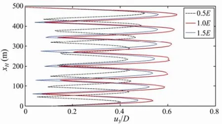
Fig.2 Effect of the elastic modulus on the number of modes and amplitudes contributing to the response of the riser.
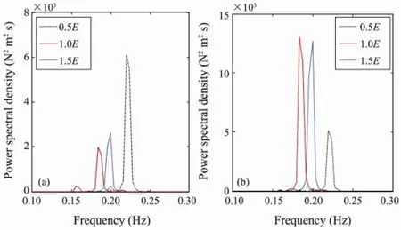
Fig.3 PSD of the riser displacement for different values of the elastic modulusE: (a) locationxH/4; (b) locationxH/2.
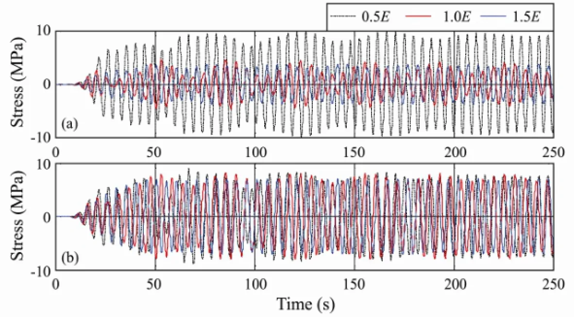
Fig.4 Bending stress histories of the riser for different values of the elastic modulus: (a) locationxH/4; (b) locationxH/2.
The inverse of the fatigue life of the riser is shown in Fig.5 for different values of the elastic modulus. For 0.5E, 1.0Eand 1.5E, the calculated minimum fatigue lives of the riser are 328.3, 37.3 and 21.3 year, respectively. The position with the minimum fatigue life point of the riser is located at a height of about 37 m above the bottom. For a given mode, the nodes are less spaced out near the sea floor, leading to higher stress and fatigue levels. This demonstrates that the fatigue life greatly increases with a decrease of the riser’s modulus of elasticity. Therefore, we propose that materials with a high strength and a low elastic modulus should be used in the fatigue-sensitive part of the riser.
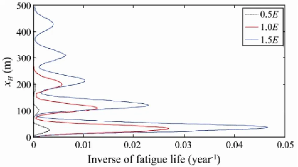
Fig.5 Inverse of the fatigue life of the riser for different values of the elastic modulus.
4.1.2 Effect of the internal flow velocity on the dynamic response
Previous studies have shown that the natural frequencies vary significantly with the internal fluid velocities, and that the natural frequency of the riser decreases with an increase of the internal fluid velocity (Meng and Chen, 2012; Menget al., 2011). Passive control of the VIV can be achieved by changing the internal fluid velocity. In our model, the top tension isTt=476.2 kN and the external flow velocity is 0.3 m s-1. The displacement profiles along the riser span are shown in Fig.6. In this plot, the mode shapes are rendered as actual displacement amplitudes. This allows to observe the degree of excitation of each mode. In the case of variations of the fluid flow rate, the response of mode 7 shows the greatest amplitude of vibration and is therefore the dominant mode forV=0 m s-1,whereas the response of mode 8 is the dominant mode for the other two velocities.
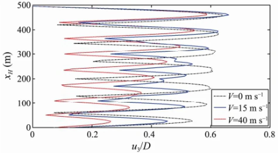
Fig.6 Effect of the internal fluid velocity on the number of modes and amplitudes contributing to the response of the riser.
Fig.7 shows the dimensionless PSD of the riser response at the locationsxH/4 andxH/2. The response frequencies obtained for the three different internal fluid velocities are listed in Table 2.

Fig.7 PSD of the riser displacement for different internal fluid velocities: (a) locationxH/4; (b) locationxH/2.

Table 2 The response frequency (Hz) for different internal fluid velocitiesV(m s-1)
In Fig.7(a), the spectra for the location andxH/4 are shown and a VIV activity can be observed for two distinct frequencies (V=0 m s-1) in the range from 0.1 Hz to 0.25 Hz. However, at a velocityV=15 m s-1, four distinct VIV frequencies can be observed. Fig.7(b) shows the corresponding spectra for the locationxH/2 where a VIV activity occurs at one (V=0 m s-1) and two (V=15 m s-1) distinct frequencies in the range from 0.1 Hz to 0.25 Hz, respectively. The observable behavior may result in a multi- mode lock-in of the cross-flow VIV. The spectra in Figs.7(a) and (b) indicate a multimode activity during a VIV event. But these multimode activities vanish and a single dominant peak appears when the fluid rate is increased toV= 40 m s-1. This is the uni-modal lock-in behavior of the riser. Based on these results, we can draw the conclusion that multimodal riser response happen for a low internal fluid velocity value.
The large variation in the number of frequencies indicates an irregular character of the response, which is corroborated by the time history of the bending stress shown in Fig.8. The time history curves forV=15 m s-1show a systematic variation which is known as beating phenomenon. The shape of the curve forV=15 m s-1in Fig.6 indicates that the response contains more than one mode which is further confirmed by Fig.7. When the two sine waves with the same amplitude are superimposed, a specific phenomenon will occur,i.e., the amplitude of the curve will exhibit slow cyclical changes.
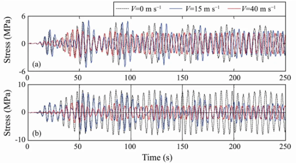
Fig.8 Stress histories of the riser for different internal fluid velocities: (a) locationxH/4; (b) locationxH/2.
Fig.9 shows the inverse of the fatigue life of the riser for different internal fluid velocities. Three different internal velocities,i.e., 0, 15 and 40 m s-1, were selected and the minimum fatigue life of the riser for each velocitywas calculated to be 37.3, 35.9 and 34.5 year, respectively. The fatigue life clearly decreases with an increase of the internal fluid velocity. The internal fluid will not only affect the response amplitudes and modes of the riser but will also lead to a decrease of the fatigue life. Therefore, more attention should be paid on its effect on the riser fatigue life during riser analysis and design.

Fig.9 Inverse of the fatigue life of the riser for different internal fluid velocities.
4.1.3 Effect of the Top Tension on the Dynamic Response
Fig.10 illustrates the effect of the top tension on the number of modes and amplitudes contributing to the response of the riser. The variation of the top tension results in a change in amplitude. Furthermore, with an increase of the pretension at the top, a mode transition occurs. But at the same time, the amplitude of the dynamic response increases with the mode transition.
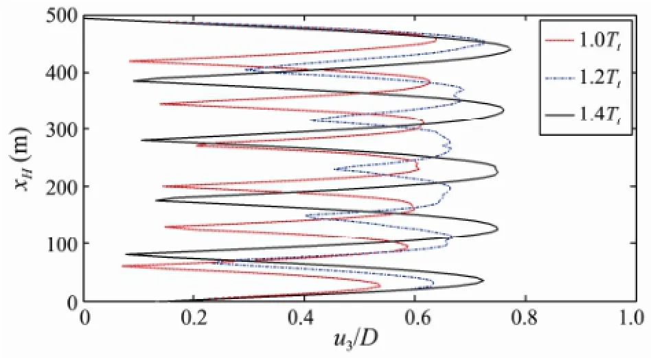
Fig.10 Effect of the top tension on the number of modes and amplitudes contributing to the response of the riser.
The dimensionless PSD and the long-term bending stress of the riser response at the locationsxH/4 andxH/2 are shown in Fig.11 and Fig.12, respectively. The response frequencies obtained for different top tensions are also listed in Table 2. As shown in Fig.11, a single dominant peak appears for the tension values of 1.0Ttand 1.4Tt, suggesting that the response is dominated by a single frequency, and the riser response is thus characterized by a single vibration mode. For the simulation done using a top tension of 1.2Tt, multiple peaks occurred in the PSD, indicating a multimode response, which would explain that more than one mode contributed to the response.
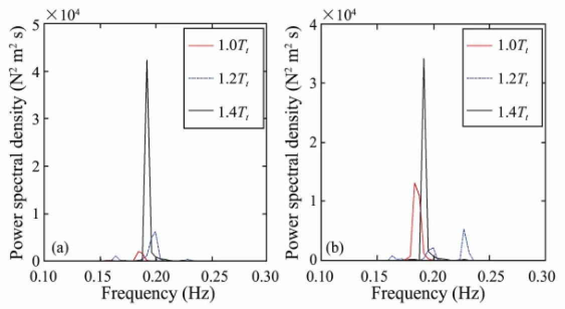
Fig.11 PSD of the riser displacement for different values of the top tension: (a) locationxH/4; (b) locationxH/2.
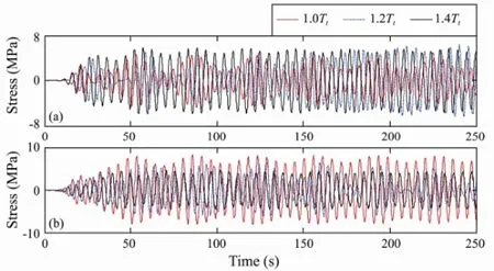
Fig.12 Stress histories of the riser for different top tension values: (a) locationxH/4; (b) locationxH/2.
Fig.13 shows the fatigue life of the riser for different top tensions,i.e., 1.0Tt, 1.2Ttand 1.4Tt, and the minimum fatigue lives of the riser were calculated to be 37.3, 67.6 and 125.0 year, respectively. With an increase of the top tension the vibration amplitudes will increase, but the mode numbers may decrease, resulting in fewer bending stress cycles.
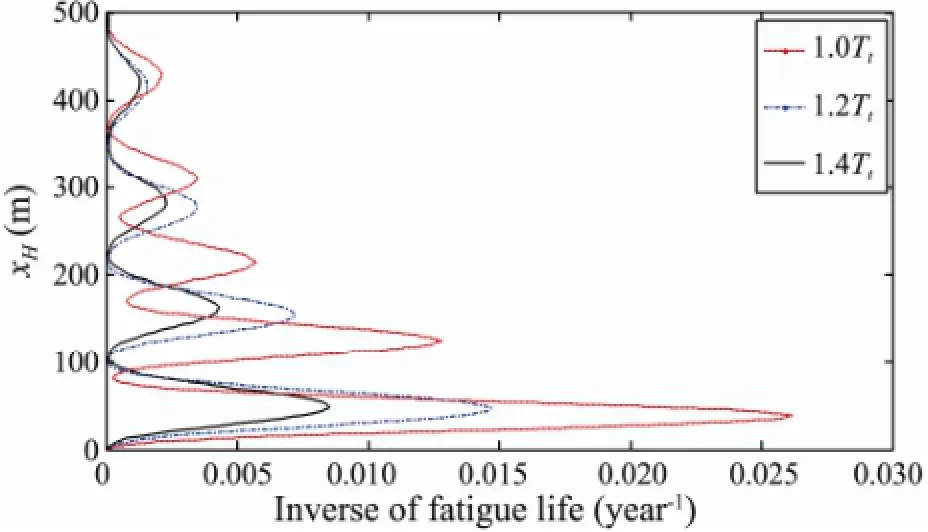
Fig.13 Inverse of the fatigue life of the riser for different top tension values.
4.1.4 Effect of the structural damping ratio on the dynamic response
The damping of the structural system can also be increased by an engineering measure to reduce the VIV,i.e., an external damper can be mounted to the riser. Its slap in the case of a structural vibration can increase the structural damping ratio nearly by a factor of three. The effect of the structural damping ratio on the contribution of the amplitudes to the response of the riser is shown in Fig.14. With an increase of the structural damping ratio, the amplitude of the dynamic response obviously decreases without mode transition.
The corresponding PSD of the riser at locationsxH/4 andxH/2 above the bottom of the riser and the long-term bending stress responses are shown in Fig.15 and Fig.16, respectively. As shown in Fig.15, the natural frequencies do not change significantly for different structural damping ratios. This means that the response is dominated by the same frequency, and the riser response can thus be characterized by different structural damping ratios.
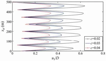
Fig.14 Effect of the structural damping ratio on the contribution of the amplitudes to the response of the riser.
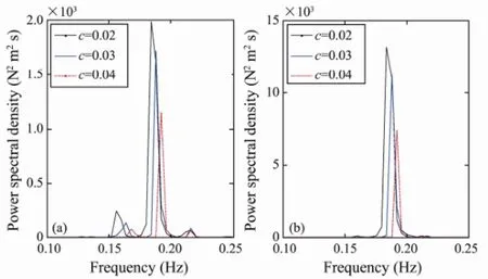
Fig.15 PSD of the riser displacement for different structural damping ratios: (a) locationxH/4; (b) locationxH/2.

Fig.16 Stress history of the riser for different structural damping ratios: (a) locationxH/4; (b) locationxH/2.
Fig.17 shows the fatigue life of the riser for different structural damping ratios. Three different structural damping ratios were selected,i.e., 0.02, 0.03 and 0.04, and the corresponding minimum fatigue lives of the riser were calculated to be 37.3, 71.4 and 278.5 year, respectively, implying that the fatigue life increases with the structural damping ratio. The structural damping ratio is therefore an important parameter to consider when designing risers, and it should be as large as possible as long as the selected value is permitted by other conditions.
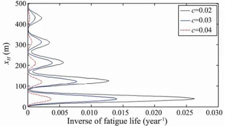
Fig.17 Inverse of the fatigue life of the riser for different structural damping ratios.
4.2 Active Control of the Structural Vibration
The second term on the right side of Eq. (8) is the reason for the VIV of the riser and will have a large impact on the VIV. In order to investigate the possibilities for an active control of the structure, external flow ratesUof 0.1, 0.2, 0.3 and 0.5 m s-1were considered in this section. Figs.18, 19 and 20 show the effect of the external flow rate on the number of modes and amplitudes contributing to the response of the riser, the corresponding PSD of the riser at locationsxH/4 andxH/2 above the bottom of the riser, and the long-term bending stress responses, respectively. It can be seen that a mode transition occurs as the external flow velocity increases. The mode numbers from 3 to 11 while the external flow rates from 0.1 to 0.5 m s-1. The dynamic response amplitude decreases and the response frequencies increase with increasing velocity.
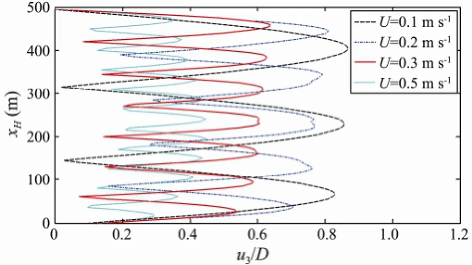
Fig.18 Effect of the external flow velocity on the number of modes and amplitudes contributing to the response of the riser.
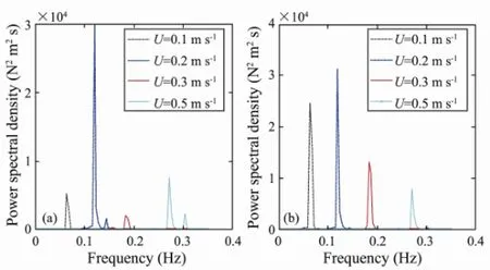
Fig.19 PSD of the riser displacement for different external flow velocities: (a) locationxH/4; (b) locationxH/2.
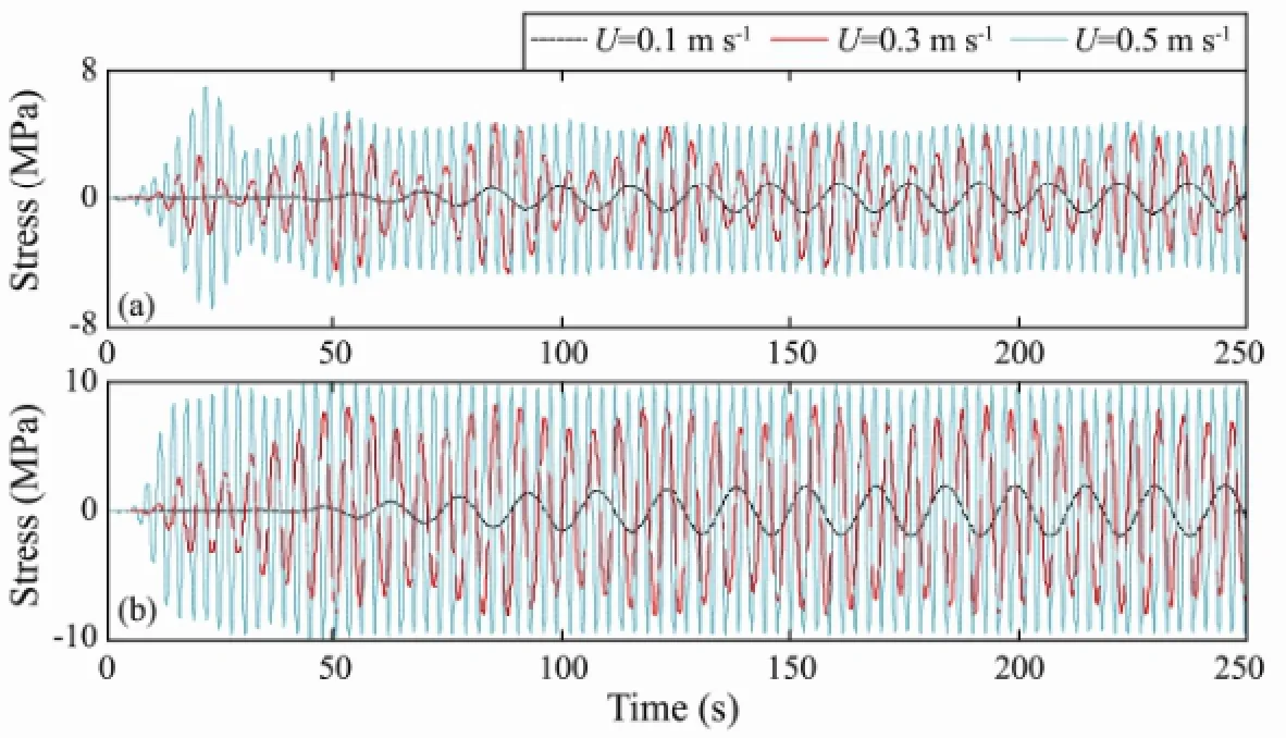
Fig.20 Stress history of the riser for different external flow velocities: (a)xH/4; (b)xH/2.
It can be concluded that, for an SCR, an increase of the external flow rate will lead to an enhancement of the frequency response and a simultaneous enhancement of the multi-modal phenomenon. Furthermore, the VIV response will become more complex.
5 Conclusions
The vortex-induced vibration and fatigue life of a steel catenary riser model were analyzed in the time domain. The influence of the riser’s parameters, such as the flexural rigidity, top tension, internal flow velocity and damping ratio, on the dynamic response and fatigue life were analyzed in detail and the following conclusions can be drawn:
1) The flexural rigidity has a significant impact on the response amplitudes and fatigue life of the riser. The fatigue life greatly increases with a decrease of the riser’s modulus of elasticity.
2) The flow of the internal fluid will affect the response amplitudes and modes of the riser, and the fatigue life decreases as the internal fluid velocity increases.
3) The top tension has a great influence on the dynamic response and fatigue life of the riser. With an increase of the top tension the vibration amplitudes will increase but the mode numbers may decrease, resulting in fewer bending stress cycles;
4) The structural damping ratio also has a great influence on the dynamic response and fatigue life of the riser. With an increase of the structural damping ratio, the amplitude of the dynamic response obviously decreases without mode transition, implying that the fatigue life increases with the structural damping ratio.
Although the possibilities to freely select the analyzed parameters are generally restricted, enough attention should be paid to these parameters during the preliminary riser design process, considering both the passive control method and the active control method.
Acknowledgements
Financial support from the China Postdoctoral Science Foundation Fund (Grant No. 2013M531563) and the Qingdao Agricultural University High-Level Talents Research Fund (Grant No. 631424) is gratefully acknowledged.
Baarholm, G. S., Larsen, C. M., and Lie, H., 2006. On fatigue damage accumulation from in-line and cross-flow vortexinduced vibrations on risers.Journal of Fluids and Structures, 22 (1): 109-127.
Bahmani, M. H., and Akbari, M. H., 2010. Effects of mass and damping ratios on VIV of a circular cylinder.Ocean Engineering, 37: 511-519.
Blevins, R. D., 1990.Flow-Induced Vibrations. 2nd edition. Van Nostrand & Co., New York, 363pp.
Chang, Y. J., Chen, G. M., Sun, Y. Y., Xu, L. B., and Peng, P., 2008. Nonlinear dynamic analysis of deepwater drilling risers subjected to random loads.China Ocean Engineering, 22 (4):683-691.
Chucheepsakul, S., Monprapussorn, T., and Huang, T., 2003. Large strain formulation of extensible flexible marine pipes transporting fluid.Journal of Fluids and Structures, 17:185-224.
Facchinetti, M. L., de Langre, E., and Biolley, F., 2004. Coupling of structure and wake oscillators in vortex-induced vibrations.Journal of Fluids and Structures, 19: 123-140.
Gu, J. J., Wang, Y., Zhang, Y., Duan, M. L., and Levi, C., 2013. Analytical solution of mean top tension of long flexible riser in modeling vortex-induced vibrations.Applied Ocean Research, 41: 1-8.
Guo, H. Y., Fu, Q., and Lou, M., 2005. Vortex-induced vibrations and fatigue life of marine risers conveying flowing fluid.Engineering Mechanics, 22 (4): 220-224 (in Chinese with English abstract).
Guo, H. Y., Li, X. M., and Liu, X. C., 2008. Numerical prediction of vortex induced vibrations on top tensioned riser in consideration of internal flow.China Ocean Engineering, 22 (4): 675-682.
Haken, H., 1983.Advanced Synergetics. Spring-verlag, Berlin, 376pp.
Iranpour, M., Taheri, F., and Vandiver, J. K., 2008. Structural life assessment of oil and gas risers under vortex-induced vibration.Marine Structures, 21 (4): 353-373.
Kaewunruen, S., Chiravatchradej, J., and Chucheepsakul, S., 2005. Nonlinear free vibration of marine risers/pipes transporting fluid.Ocean Engineering, 32 (3-4): 417-440.
Knyazeva, E. N., and Kurdyumov, S. P., 1994.Laws of Evolution and Self-Organization of Complex Systems. Nauka Publishers, Moscow, 323pp (in Russian).
Kuiper, G. L., Brugmans, J., and Metrikine, A. V., 2008. Destabilization of deep-water risers by a heaving platform.Journal of Sound and Vibration, 310 (3): 541-557.
Li, X. M., Guo, H. Y., and Meng, F. S., 2010. Fatigue life assessment of top tensioned riser under vortex-induced vibrations.Journal of Ocean University of China, 9 (1): 43-47.
Martins, C. A., and Pesce, C. P., 2002. A simplified procedure to assess the fatigue-life of flexible risers. In:The Proceedings of the 12th International Offshore and Polar Engineering Conference. ISOPE, Kitakyushu, Japan, 2: 26-31.
Meng, D., Guo, H. Y., and Xu, S. P., 2011. Nonlinear dynamic model of a fluid-conveying pipe undergoing overall motions.Applied Mathematical Modelling, 35: 781-796.
Meng, D., and Chen, L., 2012. Nonlinear free vibrations and vortex-induced vibrations of fluid-conveying steel catenary riser.Applied Ocean Research, 34: 52-67.
Xia, J., Das, P. K., and Karunakaran, D., 2008. A parametric design study for a semi/SCR system in northern North Sea.Ocean Engineering, 35 (17-18): 1686-1699.
(Edited by Xie Jun)
(Received March 21, 2013; revised April 17, 2013; accepted January 6, 2015)
© Ocean University of China, Science Press and Springer-Verlag Berlin Heidelberg 2015
* Corresponding author. Tel: 0086-532-88030416 E-mail: md1101@163.com
杂志排行
Journal of Ocean University of China的其它文章
- Effect of Dietary Lipid on the Growth,Fatty Acid Composition and Δ5 Fads Expression of Abalone(Haliotis discus hannai Ino)Hepatopancreas
- Species Composition and Diversity of Macrobenthos in the Intertidal Zone of Xiangshan Bay, China
- Evaluation of Cytotoxicity and Genotoxicity of Insecticide Carbaryl to Flounder Gill Cells and Its Teratogenicity to Zebrafish Embryos
- Purification of a Diatom and Its Identification to Cylindrotheca closterium
- Mechanical Stress Induces Neuroendocrine and Immune Responses of Sea Cucumber (Apostichopus japonicus)
- Preparation of κ-carra-Oligosaccharides with Microwave Assisted Acid Hydrolysis Method
