Design of handheld terminal for shock wave pressure measurement system
2015-03-03SHIXiaodanXIAYongle
SHI Xiao-dan, XIA Yong-le
(Key Laboratory for Instrumentation Science & Dynamic Measurement (North University of China),Ministry of Education, Taiyuan 030051, China)
Design of handheld terminal for shock wave pressure measurement system
SHI Xiao-dan, XIA Yong-le
(KeyLaboratoryforInstrumentationScience&DynamicMeasurement(NorthUniversityofChina),MinistryofEducation,Taiyuan030051,China)
Considering that it is difficult to monitor the measurement system and amend the test parameters on the scene in shock wave overpressure measurement and it is inconvenient to operate and carry traditional PC in outdoor experiments, a new handheld terminal for shock wave pressure measurement system based on ARM is designed, The handheld terminal, whose application program is developed by the software of Qt, can control the measurement system by Wi-Fi and perform the functions of monitoring the system state, transmitting the data by wireless and displaying waveforms. To prevent data loss, USB interface is designed to read the data. The test results show that the designed handheld terminal has good stability and reliability in several explosion experiments.
shock wave; handheld terminal; Qt
The shock wave is an important factor of destructive effects of projectiles, whose overpressure is reliable data to represent the power and damage probability of weapon[1-2]. Now the main ways to measure the shock wave overpressure are leads method and storage testing method at home and abroad[3-4]. The leads method has the shortcomings of cumbersome wirings and poor anti-interference ability and additional noises[5-6]. The storage testing method can make up for the deficiency of leads method, but it is difficult to monitor the measurement system and necessary to recover testing devices in order to read data after experiment[7]. With the rapid development of communication technology, wireless technology has also been applied in shock wave measurement[8-10]. As the test environment is harsh and the explosion is highly destructive, wireless sensors are typically arranged on the ground, resulting in complicated wireless transmission channel and severe signal attenuation[11], which affects the wireless transmission rate and distance greatly. Furthermore, it is difficult to monitor the system state. Once the test parameters are changed by human factors incorrectly, the test will fail. Additionally, it is inconvenient to carry traditional PC in outdoor experiments, which reduces work efficiency[12].
By studying the principle of storage test and combing WIFI technology, the new handheld terminal for shock wave pressure measurement based on ARM is designed, which has the functions of controling the system,monitoring status, and data acquisition. To prevent data loss, the USB interface is designed to read the data, improving the system reliability further.
1 Overall design of the system
The whole system includes a shock wave pressure measurement system and a handheld terminal, and the overall design diagram is shown in Fig.1.
1) Shock wave pressure measurement system
It mainly completes shock wave signal acquisition and data storage. The shock wave signal acquired by the sensors and processed by the conditioning circuit is converted into digital signal by A/D converter and stored in the memory. The WM001S made by Seanywell company is chosen as the wireless module of the system. This module has integrated micro controller (MCU) with 802.11 b/g 2.4 GHz RF transceiver chip, and has complete built-in TCP/IP protocol stack, which is installed in the measurement system as a server mode. Moreover, the system FTDI’s USB chip named FT245RL is used to output data by USB interface.
2) Handheld terminal
In order to reduce development cycle and realize portablility, ARM development board with 3.5 inch touch screen is selected to build a hardware platform and the control interface is designed by the software of Qt based on this hardware platform. To communicate with the measurement system wirelessly, the wireless network card with USB interface based RT3070 is installed into the handheld terminal. We can send instructions just by clicking on the touch screen to control the measurement system easily and complete the test task.
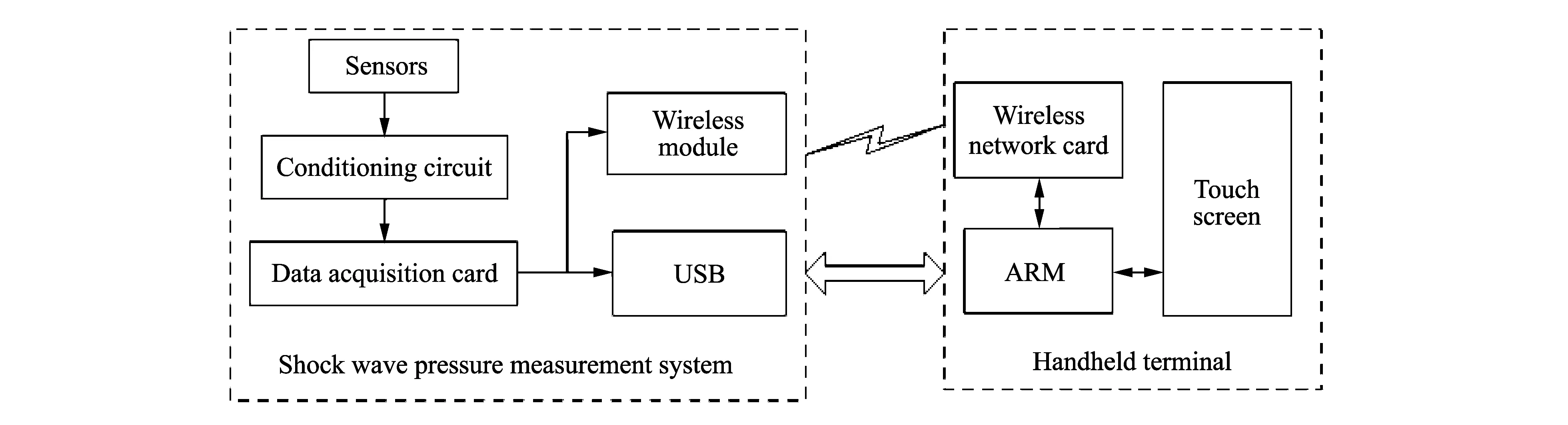
Fig.1 Overall design diagram of the system
2 Software design of handheld terminal
Handheld terminal’s main tasks done by the interactive interface are to control the testing system, monitor the state of testing system, read and display the testing data.
The software design will deal with USB correspondence, wireless communication and interactive interface, which performs the functions of setting parameters of the test system by wireless commands, reading parameters to acknowledge the working state (which can be reset in the correct state on the scene if the test parameters changed by human factors are improper), and reading data and waveforms.
The overall design diagram of the software is shown in Fig.2.
2.1 Design of USB FT245RL driver
The FTDI’s USB chip named FT245RL with the advantages of small size, high transmission speed and easy connection with the microprocessor is chosen to achieve wire communication between handheld terminal and the measurement system. However, the FT254RL driver must be designed because FTDI does not provide the driver for Linux. As USB driver is a character device driver, function “module_init( )” is utilized to complete initial loading, register USB device and apply for identification number in driver program. Different types of USB chips can be discerned by VID and PID, therefore, FT245RL chip can be found by “VID=0x0403, PID=0x6001”.
According to the file named “usb-skeleton.c” in /drivers/usb/ which belong to the framework program of USB driver in the Linux kernel sources, we can modify the driver program of FT245 is modified and the driver file named “ft245.c” is put in /drivers/char/. Then, the kernel sources can support FT245 driver by modifying the files named“Kconfig”and“Makefile”in the same directory. On the terminal the kernel can be configured by executing the command of “#make menuconfig” and the driver module can be compiled by using the instruction of“#make SUBDIR=drivers/char/modules”. Finally, the “ft245.ko” file in drivers/char/ can be got and sent to the ARM development board. Meanwhile, the command of “insmod ft245.ko” is used to accomplish dynamic loading. By means of these steps, the design of FT245RL driver is completed for USB communication between the handheld terminal and the measurement system.
2.2 Software design of wireless module
TCP protocol is connection-oriented protocol, namely in the two ends of transmission information, the connection is always established and maintained[13]. In addition, TCP has the abilities of more complex flow control and error control mechanism, data verification and retransmission. TCP protocol is often applied in design of communication system with higher reliability. Considering the advantages of TCP protocol and the characteristics of wireless module of testing system, TCP protocol is used for data transmission and point-to-point communication.
The system can apply TCP protocol to the socket communication only when both sides have established a connection before sending and receiving data in a formal way. The steps for designing TCP application program by the software of Qt are as follows: Firstly, the port of a server is in the state of circulatory monitoring all the time and it will send a “new connection” signal as soon as the port receives a connection request from a client. Secondly, the application program of sending data is developed by associating this signal with the corresponding private slots. Meanwhile, if it receives the data set by the server, the client will send a “readyRead” signal, which can be associated with the corresponding private slots to design the program of receiving data.
2.3 Design of control interface
The control interface is designed by Qt with the conjunction of graphical representation and traditional code. Firstly, the main window is established by subclass of QWainWindow derived from QWidget. Secondly, Qt Designer Form Class is built in the project to set up the windows of “setting paremeters” and “reading parameters”. The window of “waveform display” is drew by traditional code with coordinate representation and data waveform. We can call other sub windows in the main window by Qt’s specific signals and solts mechanism. The window of “setting parameters” is shown in Fig.3 and the window of “reading parameters” is shown in Fig.4.

Fig.3 “setting parameters” window
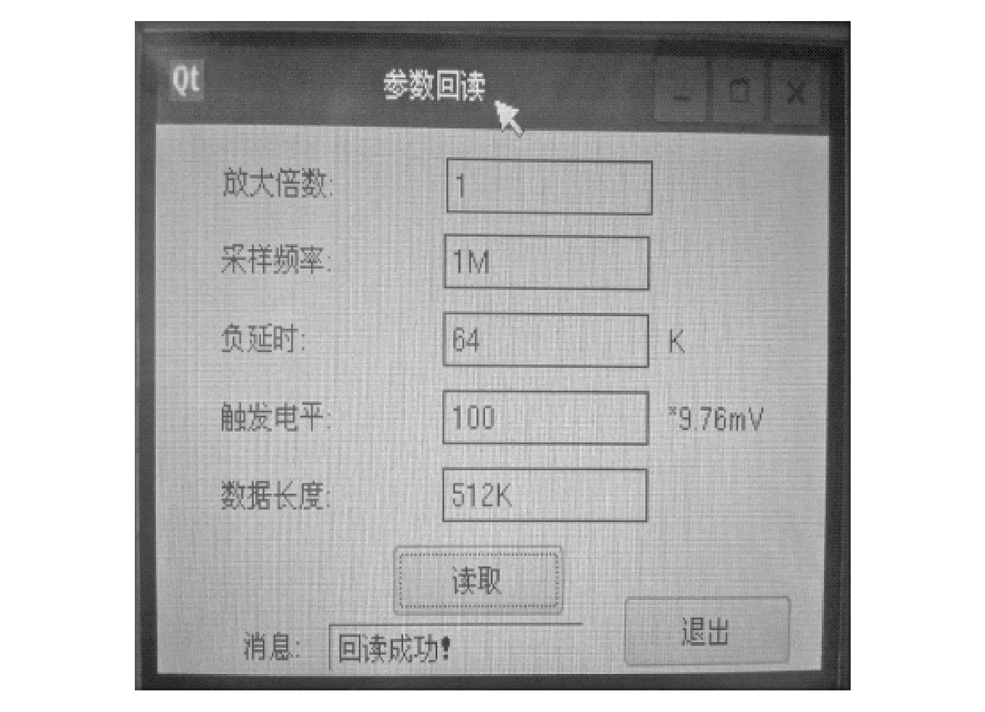
Fig.4 “reading parameters” window
2.4 Background design
The background design mainly includes USB and Wi-Fi, performing the functions of parameters setting and reading,data transmission and storage, and wavefrom display.
1) Parameters setting
It is selective to set the control instructions of parameter setting for the testing system, including: sampling frequency, triggering level, magnification, length of negative delay and the size of data storage.
The main functions of the procedure for USB are given as follows:
fd=open(“/dev/ft2450”, O_RDWR); // open the USB driver in read-only mode
FT_Status=write(fd, WriteBuffer, WriteCount); // write the control instruction to the testing system
FT_Status=read(fd, ReadBuffer, ReadCount); // read data from the testing system
The main functions of the procedure for WIFI are given as follows:
int tcppport = 5003; // the Destination Port
hostAddress = QHostAddress(“192.168.1.5”); // the destination IP
tcpClient=new QTcpSocket(this); // Create a new tcpsocket communication to server
tcpClient->connect To Host(host Address, tcpport); // connect to the TCP sever and will set a signal if succeed
connect(tcpClient, SIGNAL(connected( )), this, SLOT(send( )));
connect(tcpClient, SIGNAL(readyRead( )), this, SLOT(dateRe-ceived( )));
tcpClient ->write(byteArray); // send data
QByteArray serverData = tcpClient ->readAll(); // read data
2) Parameters reading
The corresponding control command is sent to test system and acquire the feedback information for determining whether the test system works normally and the parameters are set successfully by the statement of ui→label→setText (tr (“correlation parameters”)) and feedbacking to Label of ui file.
3) Data reading
The testing data which is read back from the testing system is saved to the file specified in a binary form. The main functions of this program are given as follows:
QFile file(“/opt/temp/11.dat”); // Open the specified file
if(!file.open(QIODevice::ReadOnly)) // Open the file in read-only mode
{ qDebug( )<<“error!”;
Return; }
Short int line;
QDataStream in(&file); // Read data from the file in.setByteOrder(QDataStream::LittleEndian);
for(b=0;b<=524287;b++)
{ In>>line;
row[b]=line;}
file.close( );
4) Waveform display
Coordinate representation and data waveform are designed by QPainter class. Firstly, the functions are declared including redrawing event function, initializing interface function and setting coordinate function in the header file. Then these functions are defined including VoidWaveDisplay::paint Event(QPaintEvent*e), voidWaveDisplay::initInterface() and void Draw::resizeEvent(QResizeEvent *e) in the file named WaveDisplay.cpp. Finally, reading data from the binary file and displaying the waveform are realized.
3 Wireless performance test and results
In order to verify the reliability and stability of wireless communication between the handheld terminal and the measurement system, the wireless performance test was conducted in actual explosion environment. The shock wave pressure measurement system was buried in the ground the same as the arrangement of ammunition experiment. Firstly, the shock wave pressure measurement system was set in the condition of waiting for trigger and the size of data storage was set at 1 MB in each test. After manual trigger or software trigger (handheld terminal), the working state of measurement system can be obtained by handheld terminal to verify the parameter reading function further. Then the test data were read by wireless communication in different ranges and the time needed was record later. The tests are repeated 3 times to read data at the same distance and the average value is taken as the transmission time. A break never occurs in data transmission and data loss during the whole process never occurs, too. That is to say, the reliability and stability of wireless communication was verified. The test results of wireless performance are shown in Table 1.
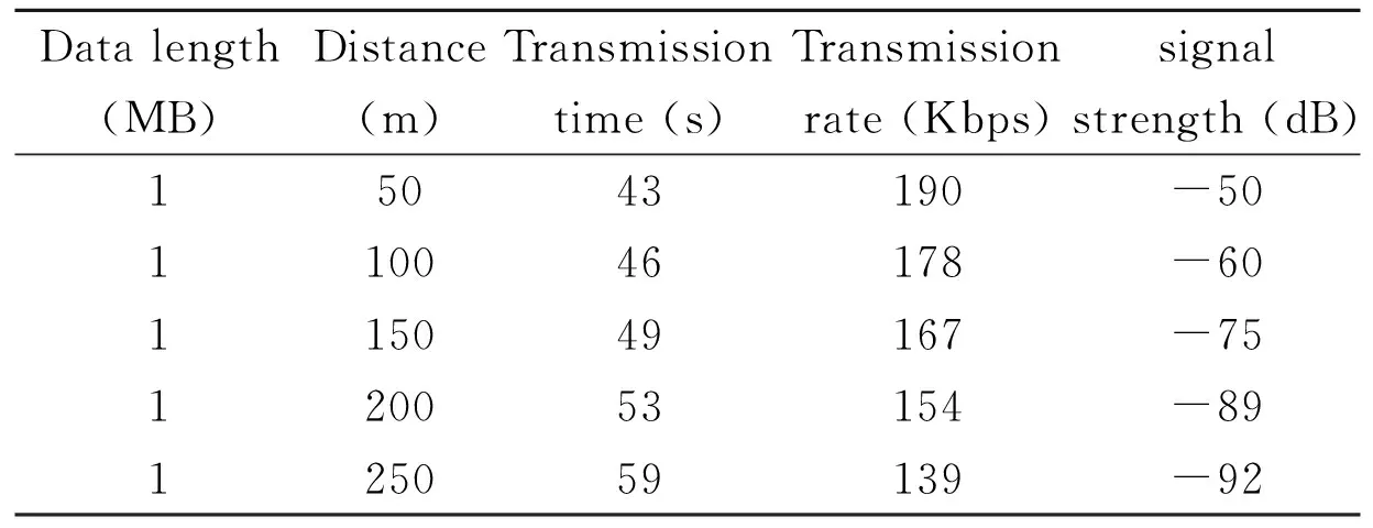
Table 1 Test results of wireless performance
The results show that the handheld teminnal can read back the working parameters of the measurement system successfully and read data reliably by wireless transmission. But the wireless transmission rate will reduce and the signal strength will weaken seriously with the increase of distance mainly because the measurement system is arranged on the ground because complicated wireless transmission channel and severe signal attenuation ground have a great effect on the wireless transmission rate and distance greatly. To solve these problems, by adjusting the distance of handheld terminal and the test system easily on the scene, the transmission performance is improved to ensure data transmission successfully. In addition, to prevent data loss, the data can be read by USB interface with wire transmission if the wirelss communication does not work.
In a static burst power test, the handheld terminal controlled the shock wave pressure measurement system successfully at a distance of 150 m and acquired the working parameters set before experiment in order to ensure that the test system is in the correct state. After explosion is over, the handheld terminal can read the test data of the shock wave pressure by wireless successfully (see Fig.5) and displayed the waveform as a result (see Fig.6).
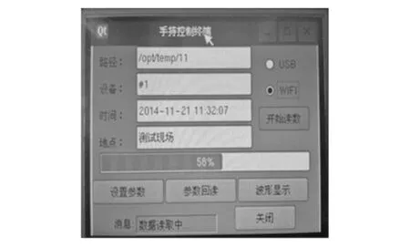
Fig.5 Result of reading data
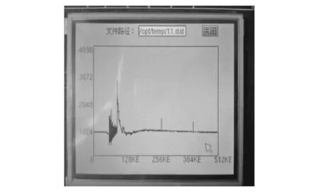
Fig.6 Experimental result
4 Conclusion
The handheld terminal designed in this paper has the advantages of low cost, portability and easy operation. Furthermore, it has the function of setting and reading the test parameters, transmiting the data by Wi-Fi and displaying the test result. In addition, by adjusting the distance of handheld terminal and the test system easily on the scene to improve the transmission performance and ensure data transmission. The problem is solved that the testing system is typically arranged on the ground, which results in the failure of data transmission, complicated the wireless transmission channel and severe signal attenuation. The validity and superiority of the proposed handheld terminal are further verified by applying it to actual measurement experiments.
[1] HUANG Zheng-ping. Explosion and shock electrical measurement technology. Beijing: Defense Industry Press, 2006: 26-49.
[2] ZHU Man-lin, SHI Cheng-ying, CAI Xing-hui, et al. Shock wave press measure of explosive based on ICP technology. Explosive Materials, 2012, 41(4): 30-32.
[3] Klaseboer E, Hung K C, Wang C, et al. Experimental and numerical investigation of the dynamics of an underwater explosion bubble near a resilient/rigid structure. Journal of Fluid Mechanics, 2005, 537: 387-413.
[4] WANG Dai-hua, SONG Lin-li, ZHANG Zhi-jie. A Stored overpressure measurement system based on ICP sensor for shock wave. Chinese Journal of Sensors and Actuators, 2012, 25(4): 478-482.
[5] MA Tie-hua, ZU Jing. Shock wave pressure measurement by memorized technique. Chinese Journal of Scientific Instrument, 2004, 25(4): 134-136.
[6] ZHAO Yan, MA Tie-hua, DU Hong-mian, et, al. Design of shock wave overpressure acquisition system based on FPGA and wireless communication. Journal of Engineering Design, 2011, 18(6): 449-452.
[7] ZHANG Zhe, LI Bao-zhu, WANG Cun-bao, et, al. Study on shock wave test system based on wireless data transmission. Transducer and Microsystem Technologies, 2009, 28(6): 7-9.
[8] Sallai J, Volgyesi P, Pence K, et a1. Fusing distributed muzzle blast and shockwave detections. In: Proceedings of the 14th International Conference on Information Fusion, Chicago, Illinois, USA, 2011: 748-755.
[9] WANG Jian, PEI Dong-xin, WANG Wei. The remote multiparameter’s data acquisition system of XXX explosion power field. Chinese Journal of Sensors and Actuators, 2013, 26(4): 516-517.
[10] DONG Bing-yu, DU Hong-mian, ZU Jing. The blast wave overpressure measuring system based on wireless-control. Chinese Journal of Sensors and Actuators, 2010, 23(2): 279-281.
[11] KONG Xiang-shan, ZHAO De-guang, WANG Da-ihua, et al. The impact analysis of wireless sensor network in low-level channel. Chinese Journal of Sensors and Actuators, 2011, 24(1): 106-110.
[12] ZHANG Xia, ZHANG Zhi-jie, XUAN Zhi-wei. Design of wireless portable terminal based on ARM and WiFi. Video Engineering , 2013, 37(15): 74-76.
[13] Hardy G T. Personal communications services. IEEE Communications Magazine, 1992, 30(6): 53-54.
冲击波测试系统的手持终端设计
石晓丹, 夏永乐
(中北大学 仪器科学与动态测试教育部重点实验室, 山西 太原 030051)
由于冲击波测试中测试系统的工作状态难以监测、 测试参数难以现场更改, 而且传统测试系统大多以PC作为控制终端, 在户外进行实验时存在着操作不便、 不易携带的问题。为此, 设计了基于RAM的新型冲击波测试系统的手持终端。 利用Qt技术设计控制界面的应用程序, 通过Wi-Fi无线控制测试系统, 实现了测试系统的状态监测、 数据的无线传输与波形显示的功能。 此外, 还设计了USB接口用于数据的有线读取, 避免了数据丢失。手持终端在多次弹药试验得到了很好应用, 具有良好的可靠性和稳定性。
冲击波; 手持终端; Qt
SHI Xiao-dan, XIA Yong-le. Design of handheld terminal for shock wave pressure measurement system. Journal of Measurement Science and Instrumentation, 2015, 6(2): 169-174.
10.3969/j.issn.1674-8042.2015.02.010
Foundation items: The 11th Postgraduate Technology Innovation Project of North University of China (No.20141147 )
XIA Yong-le (nucxyl@163.com)
1674-8042(2015)02-0169-06 doi: 10.3969/j.issn.1674-8042.2015.02.010
Received date: 2015-03-05
CLD number: TP274 Document code: A
猜你喜欢
杂志排行

Journal of Measurement Science and Instrumentation的其它文章
- Fuzzy PID control system for hose pulse experiment based on LabVIEW
- Modelling and simulation of high-speed milling chatter regeneration based on MATLAB
- Use of online electrical conductivity meter to monitor cold decomposition of carnallite
- Methane concentration detection system based on differential infrared absorption
- A fuzzy immune algorithm and its application in solvent tower soft sensor modeling