Fuzzy PID control system for hose pulse experiment based on LabVIEW
2015-03-03LIULipingLIUXinfuGONGYujieGUOHuan
LIU Li-ping, LIU Xin-fu, GONG Yu-jie, GUO Huan
(School of Mechanical Engineering, Hebei University of Technology, Tianjin 300130, China)
Fuzzy PID control system for hose pulse experiment based on LabVIEW
LIU Li-ping, LIU Xin-fu, GONG Yu-jie, GUO Huan
(SchoolofMechanicalEngineering,HebeiUniversityofTechnology,Tianjin300130,China)
The hose pulse testing bench generally uses electro-hydraulic servo system. It occupies little space, tracks signals fast and has simple structure, and therefore it is widely used in industrial control field. However, there are lots of problems such as little accuracy and instability caused by slow response of hydraulic and various interference factors. Simple proportional integration derivatiation (PID) control method of traditional pulse bench is simple in principle, but it is difficult in parameter adjustment. According to the special requirements of the control system, a PID method based on fuzzy control is proposed in the paper. This method not only retains the advantages of the conventional control system, but also ameliorates the drawbacks of parameter uncertainty, instability and lag. It has been testified that the method is practicable and can improve the precision and adaptation.
fuzzy control; servo system; proportional integration derivatiation (PID); hose pulse
0 Introduction
Hydraulic steering system is wildly used in industry field. It transfers energy by hydraulic pressure[1]. In industry, it is mainly used in position control, speed control and force control[2]. Now, the research on position control has developed fast. It is widely used both in large, heavy, special type of heavy industry and in robot micro driving. The self-adaptive fuzzy control has made progress in the position control system. At present, this technology has been very mature and reached a high level in accuracy and precision.
However, for the force control of hydraulic equipment, especially hydraulic pulse and hydraulic blasting, the control mode is still the conventional way and there exist some problems such as low accuracy, serious lag and varied parameters[3]. With the development of industrial system and new quality control standards, the quality of hose for vehicles and aviation industry has become important and it is difficult for original control method of hydraulic equipment to meet the practical requirements. More rigorous experimental scheme and more accurate experimental data are needed to improve the tester in hardware and control mode.
Since fuzzy set was first established by Zadeh L A in 1965, efforts have led to rapid development in fuzzy set theory and its applications[4]. The first known successful application of fuzzy set theory in control field was provided by Mamdani E H in 1974[5]. Compared with conventional control theory, fuzzy control does not rely on the analysis of mathematical model of the process. In essence, fuzzy logic can emulate human’s thinking and organize the approximate and indeterminate nature of the environment[6]. Fuzzy control rules frequently derive from expert knowledge and experience of workers. Considering poor stability, serious lag and time-varying parameters in hydraulic impulse test system, the paper introduces the concept of advanced fuzzy control that will strongly improve its operating performance and achieve better control effect.
1 Development status of hydraulic pulse system
Hydraulic test equipment mainly includes three parts: device under test (DUT), automated test equipment and auxiliary equipment (tooling, filtration devices, etc.)[7].
1.1 Development of hydraulic pulse test equipment
Hydraulic test equipment can be divided into three types: scientific equipment, teaching equipment and production test equipment. Scientific equipment is mainly used in scientific experiments to investigate the development of hydraulic system and hydraulic components[8]. It has been applies to the National Institute for Hydraulic Research and various hydraulic and pneumatic professional graduate schools, such as the design of twin car bombs cylinder synchronization system hydraulic test bench of Central South University, the gear pump performance test platform designed by Special Equipment Supervision and Inspection Center in Fujian and the hydraulic test bench based on LabVIEW designed by School of Mechanical Engineering of Guangxi University. Teaching hydraulic equipment is used in professional colleges and universities, such as the QCS003A hydraulic test designed by Southwest Jiaotong University. Production test equipment is used for batch testing of hydraulic components such as type test and release test. It is a also widely used in manufacturers for hydraulic components test, such as the CAT test-bed system of servo valve performance testing for a steel rolling mill equipment company designed by Zhejiang University.
1.2 Development of fuzzy control in hydraulic systems
So far, fuzzy control has been applied to various hydraulic system focusing on position control but rarely in output power control. The fuzzy control has many advantages, i.e. it is based on expert knowledge and experience of workers and it need not to establish specialized mathematical model[9]. The impact of interference and parameters on control will be greatly weakened. Therefore, it is particularly suitable for nonlinear, time-varying and time delay control system with a certain level of intelligence. Traditional PID control combined with fuzzy control will make the system both maintain the original accuracy and enhance the stability, resulting in the desired effect well.
2 Hardware design
The hydraulic servo test equipment contains machinery, electricity, hydraulics, computer and software control[10]. It consists of three components: hydraulic system, electrical control system and computer control system. The core technologies include electro-hydraulic servo control technology, electrical automatic control technology, data acquisition, data processing and measurement technology etc.[11].
2.1 Electro-hydraulic servo system
The energy backlogging, conversion, transmission and amplification rely on static pressure of the liquid medium in a certain electromechanical system to make sure the mechanical function is lightweight, scientific and maximized, which is called hydraulic principle[12]. Fig.1 is a simple hydraulic pulse generating device.

Fig.1 Simple pulse generating device
Hydraulic oil is pressed into the pipeline by pump, and then reaches the relief valve after the filter and flows through a check valve. Finally, it reaches servo valve. Excess hydraulic oil will flow back to the tank until the pressure in the pipe reaches the set pressure by relief valve. Then the energy is stored in accumulator. Therefore before servo valve, a constant pressure will be formed in pipes and accumulator, which is usually called system pressure. Servo valve can set the output pressure arbitrarily when receiving a certain voltage control signal. We can get precise waveform if we have the right control scheme.
2.2 Pulse generation mechanism
Fig.2 is the national standard for water hammer wave and Fig.3 is the national standard for trapezoidal wave. The shaded area represents that the hydraulic waveform must fluctuate within its scope.

Fig.2 Standard water hammer wave

Fig.3 Standard trapezoidal wave
In simple terms, the pulse generation process can be divided into three stages: initial state, pulse generation and waveform disappearance[13].
In the initial stage, as shown in Fig.4, the specimen with a volume ofV0has been pre-filled by the working medium. The specimen communicates with the tank through the servo valve, and at this time the pressure in the specimen isP0. The pump runs at the rated working pressurePand the discharge flow fills pressure for accumulator and excess oil flows back into the tank through relief valve.

Fig.4 Initial stage
The second stage is hydraulic pulse generation stage. As shown in Fig.5, the pump runs at the rated working pressurePand high-pressure oil enters specimen from the accumulator under the control of servo valve, finally a high hydraulic pressure pulse forms.

Fig.5 Hydraulic pulse generation stage
The last stage is that the pulse wave disappears andV0andP0are restored to the original state under the control of servo valve.
2.3 Hardware design
2.3.1 Technical specifications
The technical requirements are shown in Table 1.

Table 1 Tester’s technical requirements
2.3.2 Hydraulic system design
According to the control requirements, the system uses a closed-loop feedback control scheme. Hydraulic servo control system can adopt the form of mechanical feedback mechanism. It has advantages of simple and reliable structure, strong dirt capacity, low cost and small system damping. But its speed and accuracy is poor[14]. Unfortunately, once the design is determined, the gain is difficult to be adjusted. In addition, the fit clearance and ulnar gap that appears in the joints of mechanical parts are all nonlinear factors. That will affect control precision and stability.
Compared with mechanical form, the feedback elements and comparing elements of electro-hydraulic servo control system are all electric components[15]. Amplifying element is also electro-hydraulic servo valve which handles signals fast and has small gain with open-loop gain regulated conveniently, thus the system can be corrected easily.
In summary, this design uses electro-hydraulic servo control system. Mechanical feedback structure need not to be designed because general hydraulic system is good. Fig.6 is a hydraulic principle scheme.
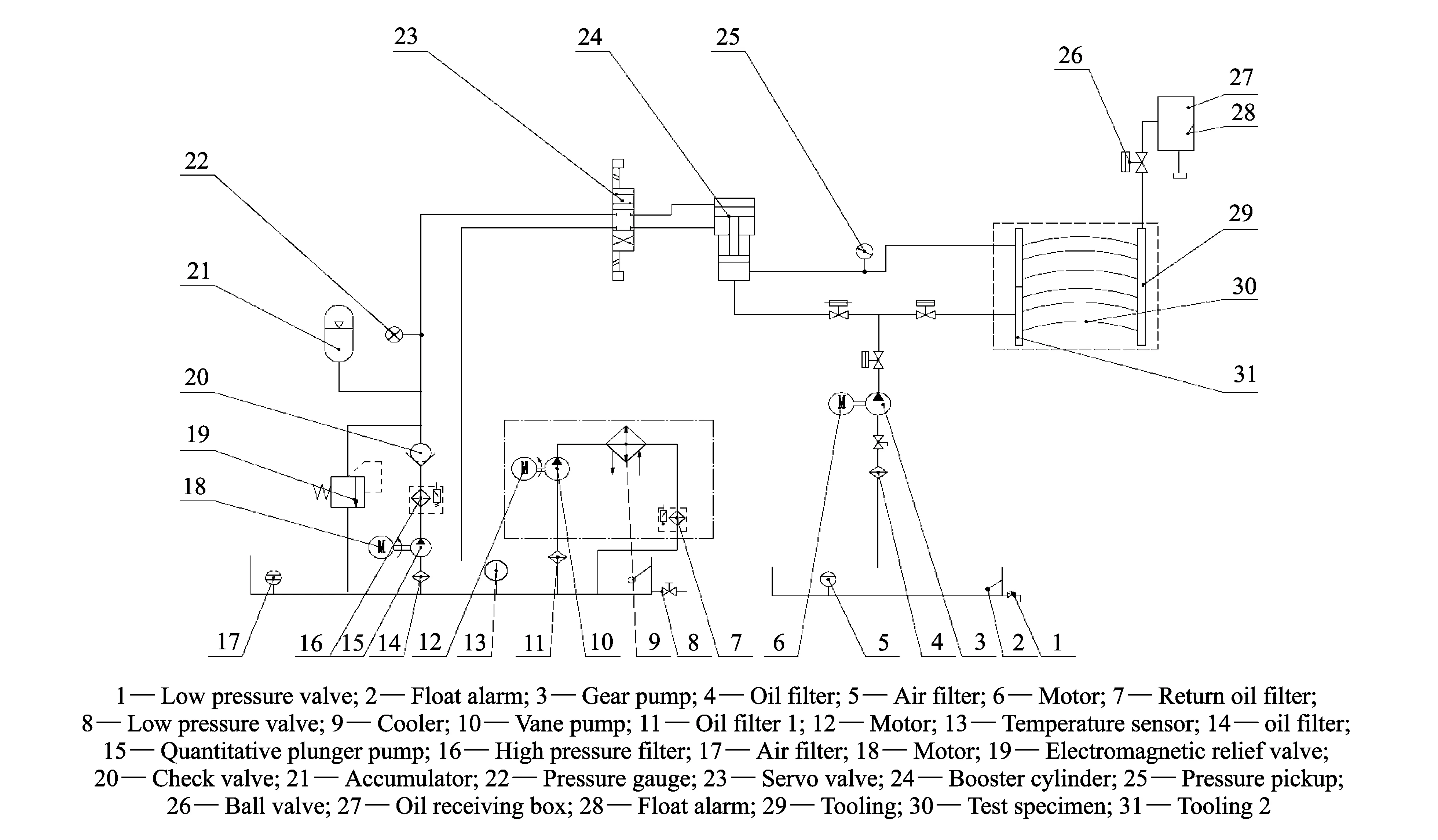
Fig.6 System schematic
3 Control system design
The traditional hydraulic servo pulse equipment commonly uses linear control or PID control[16]. Low precision and slow response are exist in linear control. Therefore, it is not suitable for high-speed pulse experiments. The traditional PID control largely alleviates the shortcomings of linear control, but PID parameters vary due to the influence of external factors. In severe cases, it will lead to the failure of the experiments.
The paper describes the control scheme of the experimental system and introduces the fuzzy control theory and the software implementation.
3.1 Fuzzy control
PID controller is a very common feedback loop control mode in industrial control. It constantly compares the collected data with a given reference, then it uses this difference as a new input value. The difference will make the system be in the reference range. Its drawback is that the PID parameters can not be adjusted automatically when the specimen volume, test temperature or the external environment change during the experiment. Slow speed boosting and uncompleted bucking also exist in this system. Trials and experiences have shown that we can adjust the parameter values(generally only value ofp) to overcome these drawbacks.
After repeated research, the system will calculatepconstantly with the change of test conditions on the basis of the original control mode. The adjustment ofpsolves the problems of slow boosting, uncompleted relief, etc. The overall control system scheme is shown in Fig.7.

Fig.7 Overall control system scheme
3.2 Fuzzy controller design
To ensure a certain control precision without complex control rules which can increase the difficulty of the design, the control system uses a two-dimensional fuzzy controller commonly used in industry[17]. Input variables of fuzzy control system are the difference(e) between the given value and the actual pressure value and its rate of change(ec). The output variable is the value ofpof PID controller. Their corresponding linguistic variables areE,ECandP. The linguistic variables are described as seven values: PB(positive big), PM(positive middle), PS (positive small), Z(zero), NS(negative small), NM (negative medium), NB(negative big)[17]. And the triangle function is membership function.
3.2.1 Determination of membership function
Based on experiences, the triangular membership function in fuzzy domain [-3, +3] is shown in Fig.8.

Fig.8 Membership of e
Considering that the error and its change rate are just predicted or estimated values, both sides of the membership function are set as station type to ensure that the controller can still work when input value exceeds the set range. Memberships ofec,pare the same.
3.2.2 Determination of fuzzy control rules
The basic principle to establish fuzzy control rules is as follows: when the system error is large or larger, control amount should be selected to nullify the error as soon as possible; when the error is small or smaller, selection of control amount should prevent overshoot to ensure system stability[19]. The fuzzy control rules are shown in Fig.9.

Fig.9 Fuzzy control rules table
3.2.3 Defuzzification
Control rules are described in Fig.1 and could also be described as the following fuzzy conditional statements:
1) If E = NB and EC = NB then U = PB
2) If E = NB and EC = NS then U = PB
…
After calculation, the fuzzy control query table is shown in Fig.10.

Fig.10 Fuzzy control query table
4 Software design
The design of control program is based on LabVIEW platform for friendly interactive interface, which is easy to be understood and operated.
The software system of hydraulic pulse test equipment mainly includes data acquisition, waveform display, data retention, data communication etc. Its functional principle is shown in Fig.11.
The control of servo valve and the data acquisition are completed by acquisition card of Advantech. The program is shown in Fig.12.
Main interface of control panel is shown in Fig.13.

Fig.11 Functional principle of software system

Fig.12 Program of data acquisition

Fig.13 Main interface of control panel
5 Field test and analysis
5.1 Experimental materials
The materials in this test equipment are steel wire braided hoses with the maximum pressure about 60 MPa or less. It consists of four parts: inner layer, middle layer, steel wire braid and the outer layer. It is mainly used for engineering and construction, materials handling, and ships. Its products are shown in Fig.14.

Fig.14 Steel wire braided hose
5.2 Field test and analysis of results
After repeated experiments and parameters adjustment, final results show that issues of slower boosting and lag are being addressed properly. As shown in Figs.15 and 16, abscissa represents the number of sampling, curve 1 represents the given waveform and curve 2 represents the experimental waveform. Lag and slow boosting are basically eliminated. Pressure control error is limited within 5%. Control accuracy is higher than the requirements of national standards.

Fig.15 Water hammer results

Fig.16 Experimental results
6 Conclusions
Focusing on the typical problems of parameter variability, slowly boosting and lagging, a new control method of hydraulic pulse equipment is presented and a hydraulic servo system with fuzzy control based on LabVIEW is proposed in this paper. It mainly include the following contents:
1) Design of hydraulic test system. We have designed hydraulic schematics of the tester that includes the calculation of hydraulic test systems and complet selection of hydraulic components depending on the load requirements and related standards.
2) By analyzing the original control method, a fuzzy control scheme is proposed and applied to the control system.
3) Software program design and human-computer interface design based on LabVIEW. Through trial and error adjustments, the final result has met the requirements of technical protocols and related standards.
Of course, there is quite a lot of research need to be studied in the future. For example, the fuzzy control rules generally come from the knowledge of experts and on-site commissioning experience, therefore some problems will exist inevitably due to subjective factors.
[1] ZHAO Yong-lin, XU Qian-wen, WANG Ming-wei. Design and development trend of the hydraulic system. ST Marine Expo Story·Discovery Science and Technology, 2012.
[2] ZHOU Yan-jing, YIN Jian-bo, GAN Lin. Study on electro-hydraulic servo control of certain artillery. Instrumental Technique, 2010, (9): 25-27.
[3] LI Pan-wei, JIAN Xun. Application of PID and fuzzy control based on PLC in hydraulic servo synchronization control system. Machine Tool & Hydraulics, 2008, 36(8): 277-279.
[4] GE Xin-cheng, HU Yong-xia. Present analysis and development trends of fuzzy control techniques. Modern Defence Technology, 2008, 36(3): 51-55.
[5] ZHANG Wei-guo, YANG Guo-zhong. Fuzzy control theory and technical application. Xi’an: Northwestern Polytechnical University Press, 2000.
[6] YANG Lun-biao, GAO Ying-jie. The principle of fuzzy mathematics and its application. Guangzhou: South China University of Technology Press, 2006.
[7] JIN Guang-jun. Research design and research of the comprehensive hydraulic pressure test platform based on Labview. Yanshan University, 2009.
[8] Laamanen A, Linjama M, Tammisto J, et al. Velocity control of water hydraulic motor. In: Proceedings of the JFPS International Symposium on Fluid Power, 2002, 5(1): 167-172.
[9] Zimmermann A, Scholz D. Proportional hydraulics work basic level. Festo Didactic GmbH & Co., 1998.
[10] ZHANG Chan. Design and research of heat alternating servo control testing system. Zhejiang University, 2006.
[11] BIAN Jun. Study of control system based on FESTO hydraulic servo test bed. Shenyang University of University, 2011.
[12] HUANG Wei-ling. Study on eight-station tube end forming machine control system based on PLC. Dongnan University, 2007.
[13] CHEN Ze-ting. The generating technology of ultra-short pulse based on multi-mode laser. Journal of Guangdong radd & TV University, 2013, (3): 102-106.
[14] SHI Wei-xiang. Status and new developments fluid power transmission and controlling. Fluid Power Transmission and Control, 2004, (1): 9-15.
[15] LI Liang. Study of digital self-examined electro-hydraulic servo system by PROFIBUS. Wuhan University of Science and Technology, 2006.
[16] ZHOU Jian-gang. Optimization for PID control method on hydraulic servo control system. Jiangnan University, 2009.
[17] SHI Ning. Reach on the fuzzy control of electro-hydraulic velocity servo system. Liaoning Technical University, 2003.
[18] ZHANG Qing. Reach on the intelligent temperature control system of sludge heat treatment furnace. Zhejiang University, 2005.
[19] MA Ming. Design and research of fuzzy control of hydraulic servo control system. Taiyuan University of Technology, 2009.
基于LabVIEW的软管脉冲实验模糊PID控制系统研究
刘力平, 刘新福, 宫玉洁, 郭 欢
(河北工业大学 机械工程学院, 天津 300130)
软管脉冲实验台一般使用电液伺服系统, 占用空间小, 原理结构简单, 信号跟踪能力强, 在工业控制领域应用广泛。 然而, 由于液压反应速度慢、 干扰因素多, 因而控制精度低, 系统不稳定; 而传统的液压脉冲实验台单纯PID的控制方式原理简单, 但参数调节困难。 本文针对控制系统的特殊要求, 提出了一种模糊PID控制方法, 既保留了原控制系统的优点, 又改善了原系统存在的参数时变、 不稳定、 滞后等缺点, 提高了系统的适应能力和精度。 经反复调试和试验, 结果表明, 该系统有效地解决了系统不稳定、 滞后严重和参数时变等问题。
模糊控制; 伺服; PID; 软管脉冲
LIU Li-ping, LIU Xin-fu, GONG Yu-jie, et al. Fuzzy PID control system for hose pulse experiment based on LabVIEW. Journal of Measurement Science and Instrumentation, 2015, 6(2): 161-168.
10.3969/j.issn.1674-8042.2015.02.009
Foundation items: High Level Talented Person Funded Project of Hebei Province (No. C2013005003); Excellent Experts for Going Abroad Training Program of Hebei Province (No.10215601D)
LIU Xin-fu (liuxf999@163.com)
1674-8042(2015)02-0161-08 doi: 10.3969/j.issn.1674-8042.2015.02.009
Received date: 2015-02-27
CLD number: TP273+.4 Document code: A
猜你喜欢
杂志排行

Journal of Measurement Science and Instrumentation的其它文章
- Design of handheld terminal for shock wave pressure measurement system
- Modelling and simulation of high-speed milling chatter regeneration based on MATLAB
- Use of online electrical conductivity meter to monitor cold decomposition of carnallite
- Methane concentration detection system based on differential infrared absorption
- A fuzzy immune algorithm and its application in solvent tower soft sensor modeling