Modelling and simulation of high-speed milling chatter regeneration based on MATLAB
2015-03-03MEIWentaoYUANLinglingZHENGYongfengLIHongsheng
MEI Wen-tao, YUAN Ling-ling, ZHENG Yong-feng, LI Hong-sheng
(Tianjin Bohai Vocational Technical College, Tianjin 300402, China)
Modelling and simulation of high-speed milling chatter regeneration based on MATLAB
MEI Wen-tao, YUAN Ling-ling, ZHENG Yong-feng, LI Hong-sheng
(TianjinBohaiVocationalTechnicalCollege,Tianjin300402,China)
Considering the deficiency in milling process parameters selection, based on the modelling of dynamic milling force and the deduction of chatter stability limits, the chatter stability lobes simulation program for milling is developed with MATLAB. The simulation optimization application software of dynamics was designed using engineering simulation software Visio Basic. The chatter stability lobes for milling, which can be used as an instruction guide for the selection of process parameters, are simulated with frequency response functions (FRFs) gained by hammer test. The validation and accuracy of the simulation algorithm are verified by experiments. The simulation method has been used in a factory with an excellent application effect.
chatter stability lobes; machining process simulation; milling
0 Introduction
The milling is a process in which the workpiece is manufactured by the milling machine based on computer numerical control (NC) technology. The most important mission for high speed milling is to determine the reasonable cutting parameters. The study on cutting force simulation and chatter has very important significance to optimization of machining parameters and working efficiency. Therefore, the genetic research and rules of the machine tool in high-speed milling chatter suppression method can effectively avoid the instability caused by vibration of the milling[1-5]. In this paper, the regenerative chatter stability domain simulation flow chart is established by analysis of high-speed milling processing and simulation analysis of MATLAB simulation algorithm[7-9]. Cutting chatter can be avoided by choosing appropriate parameters in the stable region. The simulation method has been applied in the factory to good effect.
1 Chatter theory of high-speed milling
1.1 Chatter stability lobes algorithm
The static high-speed milling force model does not consider the effect of dynamic characteristic parameters of milling, and the cutting thickness of milling process is simply considered to be nonlinear relationship between feed rate and the instantaneous angle, but the influence of vibration in milling process is ighored. Therefore, the milling parameters are changed due to workpiece vibration. As a result, the static milling force model can not describe the actual milling process, and dynamics modelling has become an inevitable trend, as shown in Fig.1.
The dynamic milling force formula can be simplified as
(1)
In the milling chatter stability analysis, the effects of dynamic milling force produced by the dynamic displacement of the tool and workpiece are considered, but the milling force of the static component of the cutting thickness is neglected. The reason is that the change of the cutting depth and cutting force direction is the periodic change of dynamic milling force coefficient matrix. In the frequency domain analysis, the vibration vector equation is described by harmonic function and transformed into frequency domain equation. Regeneration displacement equation has been obtained by the above transformation as
(2)
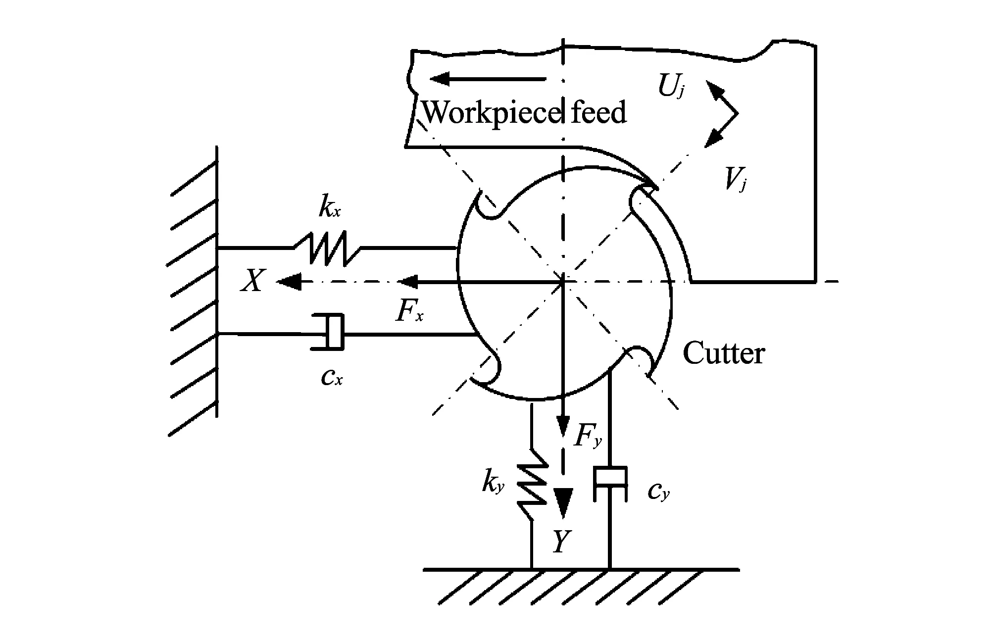
Fig.1 Schematic diagram of dynamic milling system
Substituting Eq.(2) into Eq.(1), dynamic milling force considering the regenerative vibration can be obtained by
(3)
For the flutter frequency, the mathematical formula is characteristic equation, namely characteristic equation of the closed loop dynamic milling system solutions. The mathematical formula is established based on the chatter stability analysis of closed loop feedback dynamic milling system as
(4)
(5)
According to Euler’s formula, in the actual production, axial back engagement is real. The expression of the limit shaft support engagement in the plural form has been calculated. This expression has been calculated in the chatter frequency and carried out under the condition of stable cutting. And all the conditions are critical ones as
(6)
In the actual production of milling,apmust be real, therefore imaginary part of type 7 must be zero. Then the simplified limit formula of axial cutting depth can be obtained by
(7)
In the milling cutter tooth, the cutting cycleTunder the known conditions, among the critical axial depth of cutting and spindle speed relatively has been obtained by
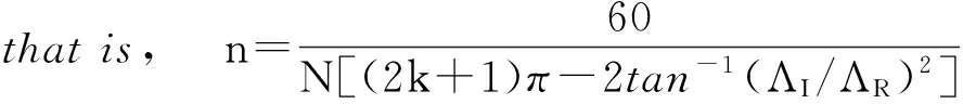
(8)
wherekrepresentsleafnumberofgraphsinthechatterstabilityanalysis.
Basedontheaboveanalysis,theultimateexpressionofhigh-speedmillingchatterstabilityhasbeenobtained.Dynamicsparametersofprocessingsystemarefrequencyresponsefunctionsoftheworkpiecemachiningpartsorthetooltippartsandhavebeenobtainedbyusingexperimentalmodalanalysismethod(Hammeringexperiment).
1.2 Simulation program design
Basedontheabovetheoreticalanalysis,thesimulationprogramisdevelopedbasedonsoftwareMATLAB7.1,andthesimulationinterfaceisdesignedbasedonMATLABGUIDEintegratedenvironment,ACCESSDatabaseandVisioBasic.Thesimulationresultsareoutputintheformofgraphicanddatafiles.TheflowchartofchatterstabilitylobesispresentedinFig.2.IncontrastwiththesimilarforeignsoftwareCUTPRO,twosimulationresultsarebasicallythesame,butourmethodhasfastersimulationspeed,asshowninTable1.
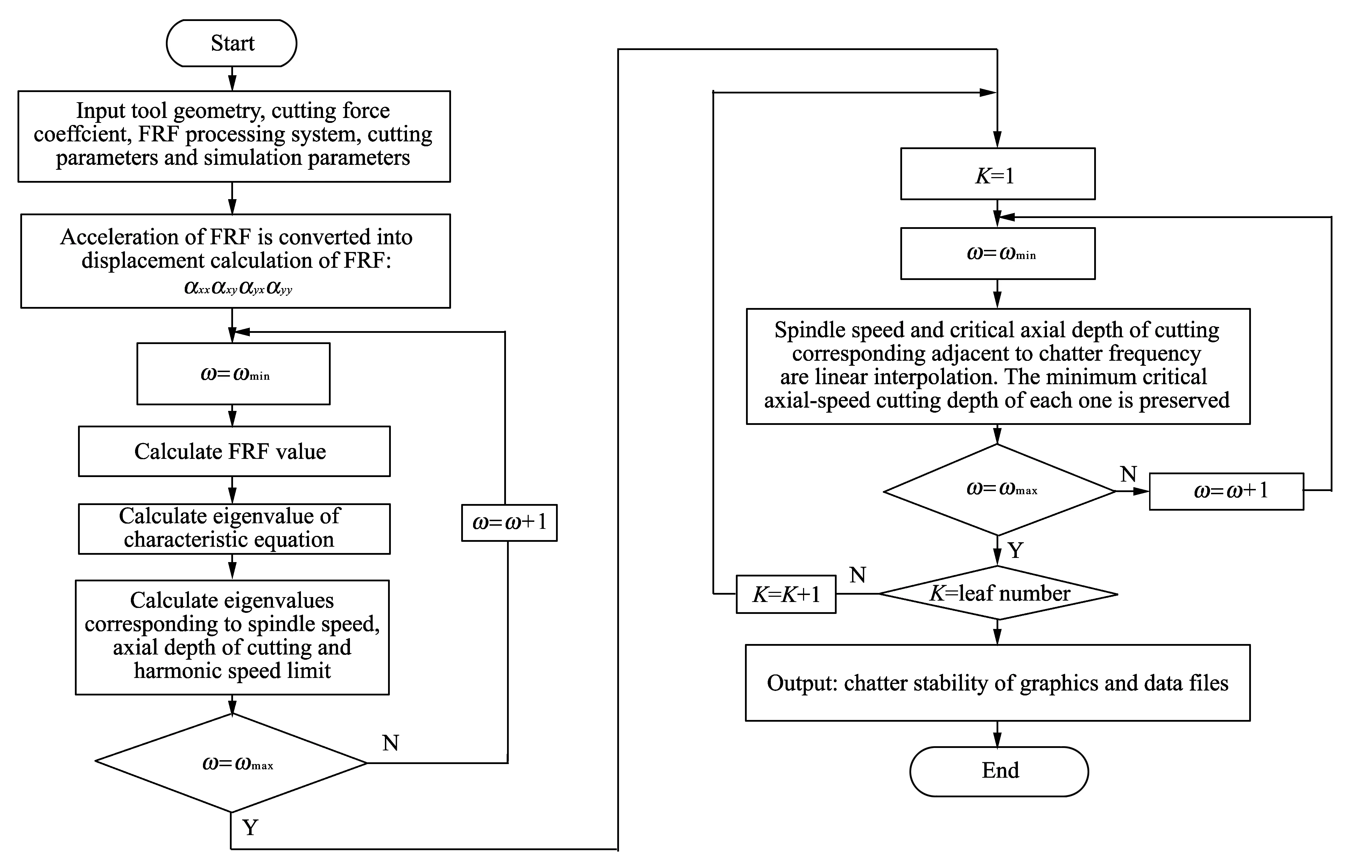
Fig.2 Flow chart of chatter stability lobes

Table 1 Comparison of simulation speed
2 Experimental verification
In order to verify the validity and accuracy of chatter stability lobes simulation algorithm, cutting experiment was carried out in FIDIA D318 high-speed machining center. The maximum speed of this machine tool is 30 000 r/min. The tool used by the experiment is the whole hard alloy cutter of Sandvik, diameter of 12 mm, 2 teeth, 30 spiral angles, overhang length 70 mm. The workpiece material is Al12, specimen size is 100×100×20 (mm). Hammer test was conducted based on “machine-tool” system. The results inXandYdirections of the FRFs were obtained. Compared with the tool, the box workpiece is considered to be a rigid body, and it can be neglected when the simulation occurs.

Fig.3 Simulation results
Fig.3 is the chatter stability lobes diagram of domain simulation. Validation experiments were performed in six selected points from the diagram (● chatter, ■ stable cutting zones). Table 2 is the processing parameters used in the experiment and verification results. Fig.3 and Table 2 show that chatter does not appear when cutting parameters of point 1, 2 and 3 are used. Chatter appears when cutting parameters points 4, 5 and 6 are used. This is fully consistent with the chatter stability lobes simulation results. Therefore, the stability simulation algorithm is proved to be effective and accurate.

Table 2 Flutter stability lobes verification (all slot milling, feed per tooth for 0.1 mm)
3 Application
The milling chatter stability lobes simulation method has been applied and good results were obtained in a large state-owned enterprise. Now taking the enterprise backbone machining center FIDIA D518 for example, the maximum speed of FIDIA D518 is 40 000 r/min, greater than parameters previously used. Dynamic parameters test and stability domain simulation were carried out on several commonly-used tools. Through the simulation experiment, cutting parameters were optimally selected. The comparison of cutting parameters and the material removal rates before and after optimization is shown in Table 3. Apparently, according to the simulation results of chatter stability lobes, cutting parameters are chosen more reasonably and the processing efficiency is higher.

Table 3 Cutting parameters before and after optimization
4 Conclusion
To solve the problem of selecting parameters in CNC milling process, based on calculation and analysis of the dynamic milling force modelling and chatter stability lobes, taking MATLAB as the development tool, the regeneration chatter milling simulation algorithm is established. The principle and steps of the algorithm are presented. The stability graphics of the whole machining system are given out. It provides a theoretical basis for the selection and optimization of milling parameters. The simulation algorithm proved to be efficient and accurate by cutting experiment.
[1] Gradisek J, Kalveam M, Weinert K. Mechanistic identification of specific force coefficients for a general end mill. International Journal of Machine Tools & Manufacture, 2004, 44(4): 401-414.
[2] Ratchev S, Liu S, Huang W, et al. A flexible force model for end milling of low-rigidity parts. Journal of Materials processing Technology, 2004, (153/154): 134-138.
[3] Ryu S H, Chu C N. The form error reduction in side wall machining using successive down and up milling. International Journal of Machine Tools & Manufacture, 2005, 45(12/13): 1523-1530.
[4] Mascardelli B A, Park S S, Freiheit T. Substructure coupling of micro end mills to aid in the suppression of chatter. Journal of Manufacturing Science and Engineering, 2008, 130(1): 1-12.
[5] ZHANG Lei, ZHENG Li. Prediction of cutting forces in milling of circular corner profiles. International Journal of Machine Tools & Manufacture, 2004, 44(2/3): 225-235.
[6] Li Z Z, Zhang Z H, Zheng L. Feedrate optimization for variant milling process based on cutting force prediction. International Journal of Advanced Manufacturing Technology, 2004, 24(7/8): 541-552.
[7] Bravo U, Altuzarra O. Stability limits of milling considering the flexibility of the work-piece and the machine. International Journal of Machine Tools & Manufacture, 2005, 45(15): 1669-1680.
[8] Gagnol V, Bouzgarrou B C, Ray P, et al. Model-based chatter stability prediction for high-speed spindles. International Journal of Machine Tools & Manufacture, 2007, 47(7/8): 1176-1186.
[9] Ozlu E, Budak E. Analytical modeling of chatter stability in turning and boring operations. Journal of Manufacturing Science and Engineering, 2007, 129: 726-732.
[10] Altintas Y, Shamoto E, Lee P, et al. Analytical prediction of stability lobes in ball-end-milling . Journal of Manufacturing Science and Engineering, 1999, 121(1): 586-592.
[11] Budak E, Altintas Y, Armarego E J A. Prediction of milling force coefficients from orthogonal cutting data. Journal of Manufacturing Science and Engineering, 1996, 118(2): 216-224.
基于MATLAB的高速铣削加工再生型颤振的建模与仿真
梅文涛, 苑苓苓, 郑勇峰, 李红升
(天津渤海职业技术学院, 天津 300402)
针对国内高速铣削加工工艺参数选择存在的问题, 基于动态铣削力建模和颤振稳定域分析计算, 以MATLAB为开发工具, 得到了铣削加工再生型颤振仿真算法。 通过模态锤击实验获得频响函数, 利用Visio Basic软件设计了圆柱立铣刀动力学仿真系统, 对整个加工系统的颤振稳定域图形进行仿真, 为铣削加工切削参数选择和优化提供了理论依据。 实验验证了该仿真算法的有效性和准确性, 并在实际应用中取得了良好的效果。
颤振稳定域; 加工过程仿真; 铣削
MEI Wen-tao, YUAN Ling-ling, ZHENG Yong-feng, et al. Modelling and simulation of high-speed milling chatter regeneration based on MATLAB. Journal of Measurement Science and Instrumentation, 2015, 6(2): 175-179.
10.3969/j.issn.1674-8042.2015.02.011
Foundation items: Tianjin Municipal Association of Higher Vocational & Technical Education Projects (No.XIV412 )
MEI Wen-tao (406091864@qq.com)
1674-8042(2015)02-0175-05 doi: 10.3969/j.issn.1674-8042.2015.02.011
Received date: 2015-03-12
CLD number: TP391.73 Document code: A
猜你喜欢
杂志排行

Journal of Measurement Science and Instrumentation的其它文章
- Rapidly determining fuel pollution level of aviation lubricating oil 50-1-4Φ by mid-infrared spectrometry
- Modeling and simulation of turbofan engine based on equilibrium manifold
- Prouhet-Thue-Morse sequence and atomic functions in applications of physics and techniques
- A fuzzy immune algorithm and its application in solvent tower soft sensor modeling
- Methane concentration detection system based on differential infrared absorption
- Use of online electrical conductivity meter to monitor cold decomposition of carnallite