Simulation and performance analysis of organic Rankine cycle combined heat and power system
2015-03-01LiuYulanCaoZhengChenJiufaXiongJian
Liu Yulan Cao Zheng Chen Jiufa Xiong Jian
(1School of Energy and Environment, Southeast University, Nanjing 210096, China)(2Lotusland Renewable Energy Holdings Limited, Shanghai 200233, China)
Simulation and performance analysis of organic Rankine cycle combined heat and power system
Liu Yulan1Cao Zheng1Chen Jiufa1Xiong Jian2
(1School of Energy and Environment, Southeast University, Nanjing 210096, China)(2Lotusland Renewable Energy Holdings Limited, Shanghai 200233, China)
Abstract:To improve the overall thermal efficiency of the organic Rankine cycle (ORC), a simulation study was carried out for a combined heat and power (CHP) system, using the Redlich-Kuang-Soave (RKS) equation of state. In the system, R245fa was selected as the working fluid. A scroll expander was modeled with empirical isentropic expansion efficiency. Plate heat exchangers were selected as the evaporator and the condenser, and detailed heat transfer models were programmed for both one-phase and two-phase regions. Simulations were carried out at seven different heat source temperatures (80, 90, 100, 110, 120, 130, 140 ℃) in combination with eight different heat sink temperatures (20, 25, 30, 35, 40, 45, 50, 55 ℃). Results show that in the ORC without an internal heat exchanger (IHE), the optimum cycle efficiencies are in the range of 7.0% to 7.3% when the temperature differences between the heat source and heat sink are in the range of 70 to 90 ℃. Simulations on CHP reveal that domestic hot water can be produced when the heat sink inlet temperature is higher than 40 ℃, and the corresponding exergy efficiency and overall thermal efficiency are 29% to 56% and 87% to 90% higher than those in the non-CHP ORC, respectively. It is found that the IHE has little effect on the improvement of work output and efficiencies for the CHP ORC.
Key words:organic Rankine cycle; combined heat and power; cycle efficiency; exergy efficiency; thermal efficiency
Received 2015-03-25.
Biographies:Liu Yulan(1990—), female, graduate; Chen Jiufa(corresponding author), male, doctor, professor, chen.jiufa@126.com.
Foundation item:Special Fund for Industry, University and Research Cooperation (No.2011DFR61130).
Citation:Liu Yulan, Cao Zheng, Chen Jiufa, et al.Simulation and performance analysis of organic Rankine cycle combined heat and power system[J].Journal of Southeast University (English Edition),2015,31(4):489-495.[doi:10.3969/j.issn.1003-7985.2015.04.010]
With increasing scarcity of non-renewable energy, the development of new energy and recovery of waste heat is increasingly important. Using a low-temperature heat source to generate power with the ORC is one of the effective ways to solve this problem. So far, much research on ORC systems has been carried out, and the form of heat source can be solar[1], geothermal[2], biomass[3], industrial waste heat[4]and so on. However, what they are most concerned about is the power efficiency. Madhawa et al.[2]compared different refrigerants in the ORC system, such as ammonia, HCFC 123, n-pentane and PF5050, however, the maximum power efficiency is not more than 10%. Li et al.[5]obtained the highest efficiency of 7.98% in the regenerative ORC with 6 kW power output. Jradi et al.[6]employed HFE7100 in an ORC system, and the maximum electric power of 500 kW has been generated with a cycle efficiency of 5.7%. Zheng et al.[7]pointed out that the cycle efficiency is steady between 5% and 6% when the heat source temperature is 90 ℃. Pei et al.[8]designed and manufactured a specifical turbine to adapt the ORC system in order to improve cycle efficiency, and obtained a maximum efficiency of 6.8%. In summary, as stated in previously mentioned studies, the present thermal efficiency is relatively low in small-scale ORC systems, both under the theoretical and experimental conditions. This phenomenon may be due to two main reasons: the first is the limitations of the research projects themselves; the second is the application limit of the low-grade heat source, which is only used for output power.
Therefore, to compensate for this inadequacy, the discharged heat is recycled in the condenser for domestic hot water by using the CHP technology, thus improving the overall thermal efficiency and reducing the exergy destruction. According to the civil architecture standard of domestic hot water, the temperature of cooling water at the condenser outlet,Tow, should be set in the range of 50 to 60 ℃. In addition, a simulation program is developed in this paper to study the ORC and optimized under different conditions. Therefore, it can provide technical support and a theoretical basis for calculating the overall system, and give guidance to the test bench in future research.
1System Introduction
1.1 Organic working fluids selection
The selection of low boiling point organic working fluid is important for optimizing the ORC system. Apart from its environmental impacts, the thermophysical property of the working fluid should be considered. Qiu[9]pointed out that R245fa was one of the best working fluids in small-scale ORC systems by proposing some evaluation standards and methods; Aghahosseini et al.[10]proved that the performance indicators of the ORC were all in the most reasonable range by using R245fa under different conditions; Saleh et al.[11]pointed out that R245fa should be considered in order to obtain a high thermal efficiency in the reheated cycle. In view of the previous studies, R245fa was chosen in this paper for a small-scale ORC system with a low-temperature heat source.
1.2 Basic ORC system
The schematic diagram of a basic ORC is presented in Figs.1 and 2. The refrigerant enters the condenser as superheated vapor at state 1 and leaves as subcooled liquid at state 4, and the cooling water will take away the heat, which is rejected during this vapor-liquid phase change process at condensing pressurePd. Then, the refrigerant enters the pump and is compressed to the evaporating pressurePein an isentropic efficiency which is determined by the pump. Then, it enters the evaporator as compressed liquid at state 5 and leaves as superheated vapor at state 8 by absorbing heat from the heat carrier at constantPe. The superheated vapor enters the expander and expands in an isentropic efficiency which is determined by the expansion ratio, and produces work by rotating the shaft connected to a generator. The pressure and temperature of the vapor drop during this process to the initial state 1. Then the refrigerant reenters the condenser, completing the cycle[12]. During this cycle, work can be produced in the expansion process, which can be used for generating electricity. Meanwhile, the cooling water at an appropriate temperature can be obtained by controlling the condensing temperatureTd, thus improving the overall thermal efficiency. Furthermore, instead of water, thermal oil serves as the heat carrier.

Fig.1 Schematic diagram of the ORC system
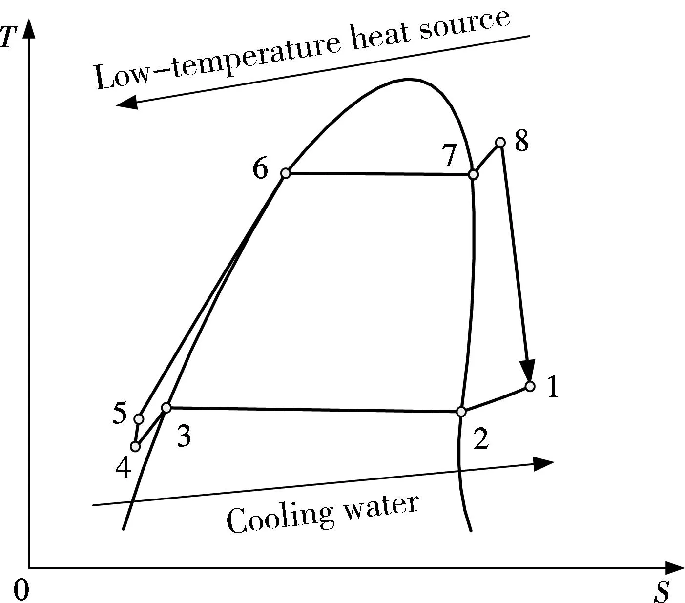
Fig.2 T-S diagram of the ORC system
1.3 ORC system with IHE
Compared with the basic ORC, the thermal load of the condenser and the cooling load of the evaporator can be reduced by adding a counter-flow IHE between the expander and pump outlet pipes, thus improving thermal efficiency. The subcooled liquid refrigerant (at state 5) absorbs heat from the superheated vapor refrigerant (at state 1) in the IHE, then they leave the IHE at state 5i and 2i, respectively, as illustrated in Figs.3 and 4.

Fig.3 Schematic diagram of the ORC system with IHE

Fig.4 T-S diagram of the ORC system with IHE
2ORC Model
A program of the ORC model is developed in this paper, which is written in VB language. The main routine connects the subroutines of working fluid, the evaporator, expander, condenser, pump and IHE. This program is simulated under ideal conditions; i.e., the pressure drops in pipes, heat exchangers and other components are ignored.
2.1 Working fluid subroutine
The physical parameters of R245fa in one-phase and two-phase regions are calculated by using the RKS equation of state with an elaborated thermodynamic frame. In addition, the following basic parameters are needed: an eccentric factor, molecular weight, critical temperature, critical pressure, the heat capacity of the liquid, and the heat capacity of the ideal gas.
In the superheated or subcooled region, the physical parameters of the working fluid, such as enthalpy, entropy, internal energy, density, can be calculated according to the temperature and pressure. While in the two-phase region, either temperature or pressure is enough for the calculation. For given temperature (or pressure), the fugacity coefficients of both the liquid phase and vapor phase are calculated and compared. If the deviation between those two fugacity coefficients is smaller than a given tolerance, the equilibrium state is reached, and the iterated pressure (or temperature) can be outputted; otherwise, a new iteration process will be repeated. In addition, other physical parameters can be calculated according to the temperature and pressure.
In short, the physical parameters of the working fluid can be calculated in this working fluid subroutine, which provides a basis for the simulation of the entire program.
2.2 Model of evaporator and condenser
The aim of the subroutine of the evaporator model is to output the iterated evaporating temperatureTe, heat exchangeQeand other outlet parameters. This subroutine is to perform iterative calculation by controlling the deviation between the iterated heat transfer area and the actual area of the evaporator. When the system is equipped with IHE, the heat exchange is
Qe=(h8-h5i)qm,r
(1)
and without IHE, it is
Qe=(h8-h5)qm,r
(2)
whereqm,ris the mass flow rate of refrigerant;h8,h5i,h5are the enthalpy per unit mass of refrigerant at state 8, 5i, and 5, respectively.
For the chevron plate heat exchanger, the empirical correlation of heat transfer coefficientkin the single-phase region can be calculated as[13]

(3)
whereλis the thermal conductivity;Deqis the equivalent diameter of the single channel in the plate heat exchanger;Reis the Reynolds number;Pris the Prandtl number;βis the angle of the herringbone plate heat exchanger.
In the two-phase region, the precise heat transfer coefficient can be calculated as[14]

(4)
wherekrlis the heat transfer coefficient of the liquid refrigerant;Bois the Boiling number;Cois the convection number;Frlis the Froude number of the liquid refrigerant.
The simulation algorithm of the condenser model is similar to that of the evaporator. In the CHP system, the discharged heat in the condenser is collected for domestic hot water. When the system is equipped with IHE, the discharged heatQdis
Qd=(h2i-h4)qm,r
(5)
and without IHE, it is
Qd=(h1-h4)qm,r
(6)
whereh2i,h4,h1are the enthalpy per unit mass of refrigerant at state 2i, 4, and 1, respectively.
The heat transfer coefficient of the two-phase fluid can be calculated as[13]

(7)
whereλlis the thermal conductivity of the liquid refrigerant;Reeqis the equivalent Reynolds number;Prlis the Prandtl number of the liquid refrigerant.
2.3 Model of expander, pump and IHE
For the selected scroll expander, the isentropic efficiency is maximum when the cycle pressure ratio matches the internal volume ratio of the expander, and it will be decreased in over- or under-expansion. The work outputWexpis
Wexp=(h8-h1)qm,r
(8)
The working fluid pump is used for elevating the pressure of the liquid refrigerant fromPdtoPe, and its simulation algorithm is similar to that of the expander. The power consumption of the pumpWpis
Wp=(h5-h4)qm,r
(9)
In the IHE, the high-pressure liquid refrigerant (at state 5) can be heated by absorbing heat from the low-pressure gas refrigerant (at state 1), and the heat transfer leads to a reduction in the thermal load of the condenser and cooling load of the evaporator, thus improving the cycle efficiency. The heat exchange in the IHEQIis
QI=(h5i-h5)qm,r=(h1-h2i)qm,r
(10)
2.4 Cycle indicators
The net work outputWnet, cycle efficiencyηcyc, exergy efficiencyηexand overall thermal efficiencyηoveare set to be the cycle indicators to evaluate the performance of the ORC system and select the optimal working conditions.
Wnet=Wexp-Wp
(11)

(12)

(13)

(14)

(15)

(16)
whereQwis the heat absorbed by the cooling water;Tambis the ambient temperature;Towis the temperature of the cooling water at the condenser outlet;Ewis the exergy of the cooling water;Tiois the temperature of the thermal oil at the evaporator inlet;Qois the heat released from the thermal oil;Eois the exergy of the thermal oil.
2.5 Main routine flowchart of system

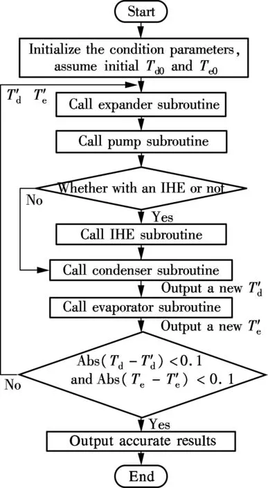
Fig.5 Main routine flowchart of the ORC system
3Simulation Results
Several graphs are plotted to show the influences ofTeandTdon cycle efficiency, exergy efficiency and overall thermal efficiency, and the effects of the CHP technology and the IHE on the basic ORC system, with a fixed flow rate of cooling water and thermal oil.
3.1 Influences of heat source and heat sink temperatures on cycle performance
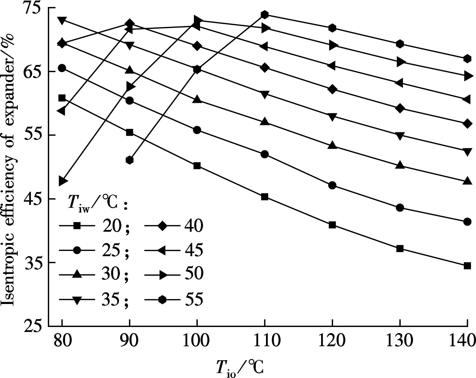
For a non-CHP ORC without IHE, the isentropic efficiency, work output and cycle efficiency vs.Tioare plotted in Fig.6 at different condenser inlet temperatures of cooling water (Tiw).
(a)

(b)
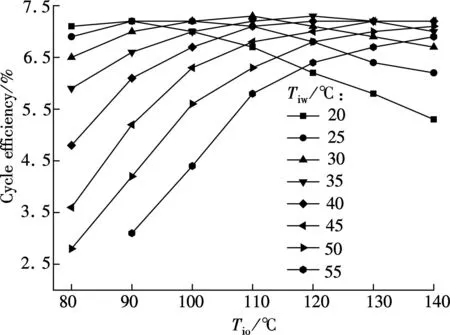
(c)Fig.6 Influences of Tio and Tiw on cycle performance. (a) Isentropic efficiency; (b) Work output; (c) Cycle efficiency
For the selected scroll expander, its optimum isentropic efficiency appears whenTiwwell matchesTioas shown in Fig.6(a), and the cycle pressure ratio is about 2.5 under these conditions. As shown in Fig.6(b), the work output increases with the increase ofTio. As shown in Fig.6(c), whenTiwis less than 35 ℃, the cycle efficiency increases first and then decreases asTioincreases. It is mainly because the isentropic efficiency decreases rapidly with the continuous increase ofTio. Thus, the increments in work output and cycle efficiency are limited. While the cycle efficiency increases but the growth rate decreases asTioincreases whenTiwis larger than 40 ℃. The main reason is that the isentropic efficiency increases first and then decreases slowly.
In summary, for the selected scroll expander, a better temperature match between the heat source and heat sink leads to larger isentropic efficiency, work output and cycle efficiency. Moreover, the optimum cycle efficiencies, in the range of 7.0% to 7.3%, are obtained when the temperature differences between the heat source and the heat sink are in the range of 70 to 90 ℃.
3.2 Influences of CHP technology
In order to improve the overall thermal efficiency and exergy efficiency, hot water can be obtained for the building by recycling the discharged heat in the condenser.
3.2.1Influence ofTioandTiwonTow
Since the temperature rise of cooling water is limited in the condenser, the lowestTiwis required for obtaining hot water. The influences ofTioandTiwonToware shown in Fig.7.

Fig.7 Influences of Tio and Tiw on Tow
It can be seen thatTowincreases asTioincreases. WhenTiwis 35 ℃,Towis less than 50 ℃ continuously with a fixed flow rate of cooling water, and water less than 50 ℃ cannot be used for domestic hot water. WhenTiwis 40 ℃,Towcan meet the standard of domestic hot water only whenTioachieves 120 ℃. Besides, the higher theTiw, the lower the temperature requirement of the heat source. Therefore, to produce hot water,Tiwrequires a minimum value of 40 ℃.
3.2.2Influence of CHP technology on exergy and overall thermal efficiency
As is shown in Fig.8(a), the exergy efficiency decreases asTiwincreases in the non-CHP ORC system. It is mainly because the higher the temperature, the greater the ambient heat loss, without consideration of heat recovery from cooling water. However, the exergy efficiency increases along with the increasingTiwin the CHP ORC system, and it is 29% to 56% better than that in the non-CHP system. In addition, the overall thermal efficiency is equal to the cycle efficiency in the non-CHP system, but it reaches 90% or higher in the CHP system (see Fig.8(b)). Therefore, the use of CHP technology will further improve the utilization rate of low-temperature heat sources. However, under actual conditions, the higher the temperature, the greater the heat loss; therefore, the overall thermal efficiency will decline.
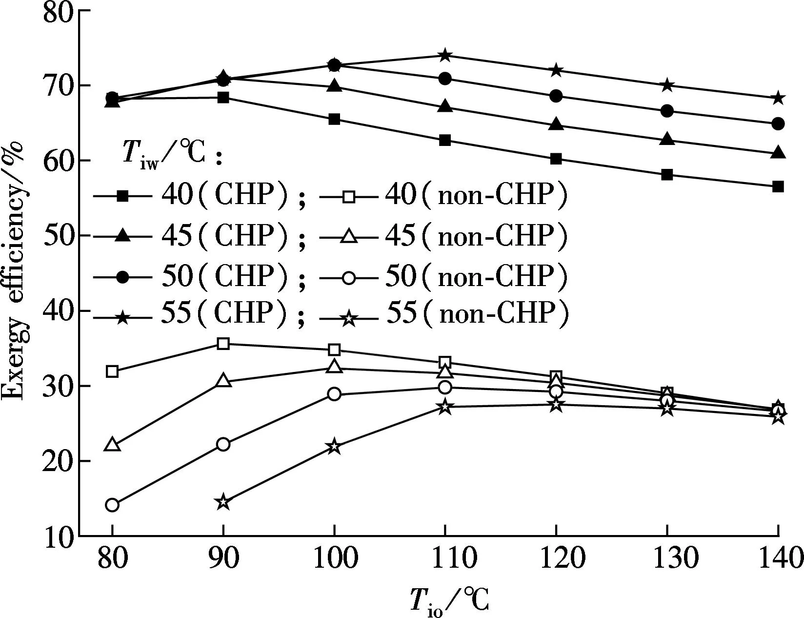
(a)

(b)Fig.8 Influence of CHP technology on efficiency. (a) Exergy efficiency; (b) Overall thermal efficiency
3.3 Influence of IHE on cycle indicators
For the CHP ORC systems with and without IHE, whenTiwis 45 ℃, the cycle indicators vs.Tioare plotted in Fig.9.

(a)
It can be seen from the simulation results that, as the heat source temperature increases, the trends of performance curves remain unchanged by adding an IHE, and the performance improves somewhat. The work output in a cycle with an IHE is 0.06 to 0.13 kW larger than that without an IHE, and the growth of exergy efficiency and cycle efficiency are only about 1.3% and 0.6%, respectively. Therefore, from the simulation results under ideal condition, IHE has little effect on the improvement of the performance parameters of the CHP ORC system. Besides, based on heat loss, cost, complexity and other factors, IHE is not strongly recommended for an actual ORC plant.
4Conclusions
1) For a non-CHP ORC without IHE, optimum cycle efficiency is related to the optimum pressure ratio. For the scroll expander selected in this paper, the optimum cycle efficiencies of 7.0% to 7.3% are obtained when the temperature difference between the heat source and the heat sink is in the range of 70 to 90 ℃.
2) For a CHP ORC, to produce hot water, the heat sink inlet temperature requires a minimum value of 40 ℃. In contrast to the non-CHP system, the use of the CHP technology will improve exergy efficiency and overall thermal efficiency by 29% to 56% and 87% to 90%, respectively.
3) The usage of the IHE will raise the exergy efficiency and cycle efficiency of only about 1.3% and 0.6%, respectively. Therefore, IHE has little effect on the improvement of the efficiencies of the CHP ORC system. Besides, based on heat loss, cost, complexity and other factors, IHE is not strongly recommended for an actual ORC plant.
References
[1]Manolakos D, Kosmadakis G, Kyritsis S. On site experimental evaluation of a low temperature solar organic Rankine cycle system for RO desalination[J].SolarEnergy, 2009, 83(5): 646-656.
[2]Madhawa H H D, Golubovic M, Worek W M, et al. Optimum design criteria for an organic Rankine cycle using low-temperature geothermal heat sources[J].Energy, 2007, 32(9): 1698-1706.
[3]Liu H, Shao Y J, Li J X. A biomass-fired micro-scale CHP system with organic Rankine cycle (ORC)-thermodynamic modeling studies[J].BiomassandBioenergy, 2011, 35(9): 3985-3994.
[4]Wei D H, Lu X S, Lu Z, et al. Performance analysis and optimization of organic Rankine cycle (ORC) for waste heat recovery[J].EnergyConversionandManagement, 2007, 48(4): 1113-1119.
[5]Li M Q, Wang J F, He W F, et al. Construction and preliminary test of a low-temperature regenerative organic Rankine cycle (ORC) using R123[J].RenewableEnergy, 2013, 57(3): 216-222.
[6]Jradi M, Li J X, Liu H, et al. Micro-scale ORC-based combined heat and power system using a novel scroll expander[J].InternationalJournalofLow-CarbonTechnologies, 2014, 9(2): 91-99.
[7]Zheng N, Zhao L, Wang X D, et al. Experimental verification of a rolling-piston expander that applied for low-temperature organic Rankine cycle[J].AppliedEnergy, 2013, 112(16): 1265-1274.
[8]Pei G, Li J, Li Y Z, et al. Construction and dynamic test of a small-scale organic Rankine cycle[J].Energy, 2011, 36(5): 3215-3223.
[9]Qiu G Q. Selection of working fluids for micro-CHP systems with ORC[J].RenewableEnergy, 2012, 48(6): 565-570.
[10]Aghahosseini S, Dincer I. Comparative performance analysis of low-temperature organic Rankine cycle (ORC) using pure and zeotropic working fluids[J].AppliedThermalEngineering, 2013, 54(1): 35-42.
[11]Saleh B, Koglbauer G, Wendland M, et al. Working fluids for low-temperature organic Rankine cycles[J].Energy, 2007, 32(7): 1210-1221.
[12]Onkar Singh.Appliedthermodynamics[M]. New Delhi, India: Mechanical Engineering Department, Harcourt Butler Technological Institute, 2009.
[13]García-Cascales J R, Vera-García F, Corberán-Salvador J M, et al. Assessment of boiling and condensation heat transfer correlations in the modelling of plate heat exchangers[J].InternationalJournalofRefrigeration, 2007, 30(6): 1029-1041.
[14]Quoilin S. Sustainable energy conversion through the use of organic Rankine cycles for waste heat recovery and solar applications[D]. Liège, Belgium: University of Liège, 2011.
doi:10.3969/j.issn.1003-7985.2015.04.010
杂志排行
Journal of Southeast University(English Edition)的其它文章
- Mitigation of inter-cell interference in visible light communication
- Modified particle swarm optimization-based antenna tiltangle adjusting scheme for LTE coverage optimization
- Distribution algorithm of entangled particles for wireless quantum communication mesh networks
- Kernel principal component analysis networkfor image classification
- CFD simulation of ammonia-based CO2 absorption in a spray column
- Experimental investigation on heat transfer characteristics of a new radiant floor system with phase change material
