Mitigation of inter-cell interference in visible light communication
2015-03-01AghaYasirAliZhangZaichenAbdeldimeAbdelgaderZongBaiqing
Agha Yasir Ali Zhang Zaichen Abdeldime M.S.Abdelgader Zong Baiqing
(1National Mobile Communications Research Laboratory, Southeast University, Nanjing 210096, China)(2 ZTE Corporation, Shenzhen 518057, China)
Mitigation of inter-cell interference in visible light communication
Agha Yasir Ali1Zhang Zaichen1Abdeldime M.S.Abdelgader1Zong Baiqing2
(1National Mobile Communications Research Laboratory, Southeast University, Nanjing 210096, China)(2ZTE Corporation, Shenzhen 518057, China)
Abstract:This paper proposes the orthogonal and non-orthogonal schemes in the interference environments for visible light communication (VLC) systems. The proposed schemes pay attention to the case when different bit streams from multiple cells are simultaneously transmitted, which consequently causes inter-cell interference (ICI) and greatly deteriorates the bit error rate (BER) and channel capacity performance of the system. The performance of the new developed multi-cell system in indoor VLC systems is evaluated. The bipolar phase shift keying (BPSK) modulation scheme with orthogonal pulses (OPs) for multiple cells environments is employed to mitigate the ICI problem and improve the BER and channel capacity performances. Since the use of different OPs in each cell requires more number of OPs, which requires high bandwidth, OPs are reused at certain distances. Three different schemes, which are OPs, orthogonal and non-orthogonal pulses (NOP) reuse, are compared. This paper investigates the impact of using these schemes and compared their performances in the ICI environments. The BER and channel capacity using the proposed schemes are comprehensively examined. Simulation and theoretical results show that the OPs schemes are more effective in the interference areas of the room and significantly outperform NOP.
Key words:visible light communication; inter-cell interference; orthogonal pulses
Received 2015-03-09.
Biographies:Agha Yasir Ali (1979—), male, graduate, aghayasirali@hotmail.com; Zhang Zaichen(corresponding author), male, doctor, professor, zczhang@seu.edu.cn.
Foundation items:The National High Technology Research and Development Program of China (863 Program) (No. 2013AA013601), the National Natural Science Foundation of China(No. 61223001), the Natural Science Foundation of Jiangsu Province (No.BK20140646), the Research Fund of National Mobile Communication Research Laboratory (No.2014A03, 2014B03, 2014B04), the Research Fund of Zhongxing Telecommunication Equipment Corporation, the Fundamental Research Funds of the Central Universities (No.2242014K40033), the United Creative Foundation of Jiangsu Province (No.BY2013095-1-18).
Citation:Agha Yasir Ali, Zhang Zaichen, Abdeldime M.S. Abdelgader, et al. Mitigation of inter-cell interference in visible light communication[J].Journal of Southeast University (English Edition),2015,31(4):437-442.[doi:10.3969/j.issn.1003-7985.2015.04.002]
In recent years, visible light communication (VLC) has emerged as a promising technology that has been used to support communication systems in special scenarios such as hospitals, conference rooms and universities[1]. VLC has been the object of extensive interest over the past few years. Many potential applications for this technology have been suggested. They refer to optical wireless communication using the visible light spectrum from 380 to 780 nm. VLC transmits data by intensity modulation on optical sources, such as light emitting diodes (LEDs) and laser diodes. Multiple LED sources are commonly employed in typical indoor environments because the optimum illuminance can be met at 300 to 1 500 lux for sufficient illumination[1].
Recently, the study of the multi-cell VLC system has emerged as an important research topic. One of the major problems in VLC systems is inter-cell interference (ICI) due to the overlapping of images from multiple cells. The multiple input multiple output (MIMO) system for multi-user environments are introduced and simulation results are presented in Ref.[2]. The limitation of this system is that it cannot work in the central area and middle corners of the room. The complete area of the room is covered with multiple cells[3], as shown in Fig.1. In some areas, the images overlap. Another solution is proposed in Ref.[4], in which cell arrangement is proposed for multi-cell VLC systems to reduce the signal-to-noise ratio(SNR) fluctuation, but this technique needs a greater number of cells and some parts of the room will not be covered by communication. Guerra-Medina et al.[5]proposed an optical code-division multiple accesses (OCDMA) system for multi-user VLC, which utilizes random optical codes (ROCs) as coding sequences, thus increasing the implementation complexity of the system. In the same context, an indoor VLC system which supports multiple accesses under line-of-sight (LOS) constraints is investigated in Ref.[6], but the room coverage problem remains unsolved. Moreover, Chen et al.[7]proposed a pre-coding multi-user MIMO indoor VLC system. Their main problem is the separation of the receiving data for different user terminals. Some other schemes were proposed in Refs.[8-9]. The optical detectors with different fields of view (FOV)are utilized and the influence of the FOV of the proposed system is analyzed, but the FOV of the detectors cannot be changed. Rahaim et al.[3]eliminated the ICI by using frequency partitioning. The available bandwidth is divided intoKsslots and the neighboring cells utilize separate frequencies to eliminate interference at interference regions. However, this scheme requires LEDs with a high bandwidth.
This paper investigates the interference problem in the interference areas and proposes a scheme to eliminate the ICI by using orthogonal pulses (OPs), which can be generated by various techniques as given in Refs.[10-11]. To extend the network coverage and provide communication for user terminals in all locations of the room, a novel approach is proposed. It improves the bit error rate (BER) and the capacity performances of the VLC system by eliminating ICI. Due to the increase of ICI in some areas, approximately equal power is received from several cells, and OPs are figureted. As we increase the number of OPs, a high bandwidth LEDs is required. The requirement of high bandwidth LEDs can be managed by reusing OPs at certain distances in the room. The contribution of this work is to provide communication for the whole area of the room and mitigate the ICI in the overlapping areas by using OPs.
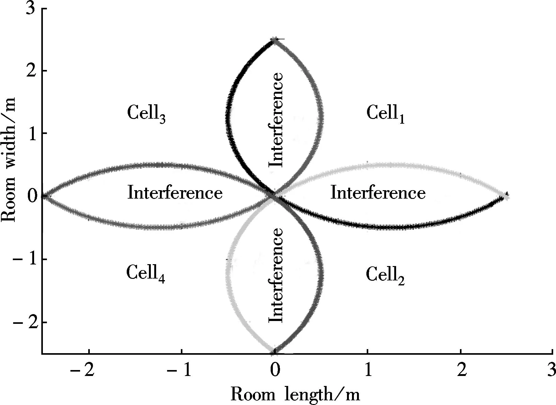
Fig.1 Foot prints of cells and interference areas in the room
1The Model of Proposed System
In this paper, a model for the source, reflectors, and receiver is considered in an empty square room. Also, the proposed techniques can be extended to other rooms in a straightforward manner. For a low cost VLC system, the most viable modulation is the intensity modulation and direct detection (IM/DD), in which the desired waveform is modulated onto the instantaneous power of the carrier. Modeling a VLC link as a linear baseband, the time-invariant system has impulse responseh(t) with signal independent additive noiseσ(t). The visible-light channel is modeled as a linear optical additive white Gaussian noise (AWGN).
yr(x,y,z)(t)=Rh(t)*x(t)+σ(t)
(1)
whereyr(x,y,z)(t) is the photo-detector current and it represents the photo sensitivity of the photo-detector (in A/W);x(t) is the instantaneous input pulse power. The average time transmitted optical power is given by[3,12]

(2)
The average received optical power generally can be determined by[12]

(3)
CLOS=(l+1)APDγcosl(φ)g(ψ)T(ψ)cofcos(ψ)
In this paper, the line of sight(LOS) and non line-of-sight (NLOS) links are considered. The DC gain on the first reflectionHrefis

(4)
CNLOS=(l+1)APDγcosl(φ)g(ψ)T(ψ)cofcos(ψ)
whereCLOSandCNLOSare the variables used in Eq.(3) and Eq.(4);dis the distance between the receiver and transmitter;D1is the distance between the transmitter and reflective point;D2is the distance between reflective point and receiver;γis the reflectance factor; dAis the reflective area of the small region;αis the angle of irradiance to the receiver;βis the angle of incidence to the receiver;lis the order of Lambertian emission;APDis the receiving area;φis the irradiance angle;ψis the angle of incidence;T(ψ)cofis the signal transmission coefficient of an optical filter;ψcis the FOV;pis the refractive index;g(ψ) is the gain of the optical concentrator[1].

(5)
In the LOS and NLOS, the received power is generally determined by[12]
Pr=HLOS(0)PtLOS+∑Href(0)Ptref
(6)
This paper is designed for multiple cells to solve the interference problem in multiple cell environments. The OPs are transmitted as bipolar phase shift keying (BPSK). A binary ‘1’ is represented by a positive pulse and binary ‘0’ is represented by a negative pulse.
The proposed scheme is designed to eliminate ICI from multiple cells in the room. Fig.1 shows the foot prints of interference areas between cells. This scheme is mainly effective in those areas. As defined in Ref.[3], the maximum area can be covered by cells to provide communication in every area of the room by adjusting the minimum acceptable power. Therefore, the covered area of each cell is π(λ)2/2Nfor a square shaped room, whereλis the length of the room andNis the number of cells.
The maximum power received at them-th receiver from thek-th cell can be obtained from Eq.(6).
Pr(k,m)=H(0)LOS(k,m)Pt(k)LOS+∑H(0)(k,m)refPt(k)ref
(7)
wherePt(k)is the transmitted power from thek-th cell. The total power received from the cell to them-th receiver is

(8)

The receiver only passes the signal from thek-th cell because the signals from other cells are orthogonal to the correlation function of them-th receiver, as shown in Fig.2.
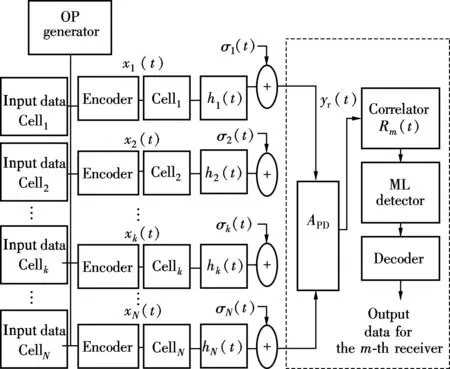
Fig.2 The VLC proposed model
2Analysis
The multiple cells (cell1,cell2,…,cellN) are transmitting OPs (x1(t),x2(t),…,xN(t)), respectively. Allowing them-th receiver to receive all the pulses from LOS, the NLOS and matched filter correlator is

(9)

(10)
where the maximum power is received at timetd, andRmis the correlator function of them-th receiver,

(11)
In the case of non-orthogonal pulses (NOPs), all the cells use the same pulse and bandwidth for transmission. Therefore, the signals from other cells in Eq.(11) are considered as noises and they are not equal to zero. The SNR cannot be affected by the bandwidth but it is affected by the ICI and distance. Using Eq.(7) and Eq.(8), the SNR from thek-th cell is defined as[3]

(12)
whereWkrepresents the bandwidth of thek-th cell.
The channel capacity of NOPs is the same for all cells because all pulses are using the same bandwidth. The capacity of NOPs is defined as

(13)
The proposed scheme improves SNR by using OPs. When each cell uses an OP, the receiver can easily distinguish signals from the principle cell. The bandwidth of OPs used by cells can be defined as

(14)
whereTsis the symbol time. From Eq.(14), the number of OPs requires high bandwidth LEDs. The high bandwidth pulses can affect the SNR. The greater the number of pulses is minimized by reusing OPs at certain locations in the room. Substituting Eq.(14) and Eq.(11) into Eq.(12), the SNR for OPs can be derived as

(15)
Note that the SNR performance of OP is affected by its high bandwidth but NOP is affected by interference.
Substituting Eq.(14) and Eq.(15) into the Shannon capacity figure, the channel capacity can be improved by using OPs, specifically in interference areas,

(16)
As BPSK modulation technique is used in this scheme, the theoretical BER can be calculated as

(17)
Consequently, the BER of NOPs is given as

(18)
From Eq.(7) and Eq.(11), we can obtain

(19)
3Simulation Results and Discussion
The setup of simulation program for the indoor VLC system contains four cells which are located in the ceiling[3,12]and two types of comparisons are given which are NOP with 4OP and NOP with 2OP. The receiving plane is 1.85 m away from ceiling. The center of the room is selected as the origin of the coordinate, and the other parameters of the proposed system are listed in Refs.[11-12].
Without loss of generality, we assume two typical scenarios to simulate BER and the capacity performances of the system by considering different pulses distributed in different cells.
Obviously, the proposed scheme is effective, particularly at the center and the interference area of the two cells, as shown in Fig.1. From the analytical results, it is observed that the capacity and BER performances are mainly affected by the distance and ICI; however, the proposed scheme is mainly affected by distance.
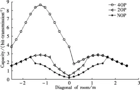
Fig.3 Channel capacity and bandwidth
As depicted in Fig.3 to Fig.5, the overall capacity performance is significantly improved by using the proposed scheme. Fig.3 shows the difference of channel capacity among 4OP, 2OP and NOP. Note that the highest channel capacity is obtained when using 4OP, and the high bandwidth cell obtains high channel capacity. In the case of 2OP, the diagonal cells share the same pulse; therefore, ICI occurs in diagonals of the room and the channel capacity deteriorates in diagonal cells. In the case of NOP, the capacity is almost identical between cells, because the same bandwidth pulses are used. The channel capacity of NOPs is affected by ICI and decreases rapidly in the interference area compared to OPs. Particularly, at a high SNR, the difference between OPs and NOPs is significantly high.
Fig.4 shows the difference of the channel capacity in the three-dimensional pattern between 4OP and NOP. Note that the maximum response is obtained by cell1and cell3because they are using the highest bandwidth. Cell4uses the lowest bandwidth, therefore, it produces a low channel capacity. As depicted in Fig.5, the two diagonal cells use the same bandwidth in the case of 2OP; therefore, only the channel capacities of diagonal cells are identical.
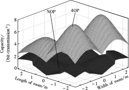
Fig.4 Channel capacity of 4OP and NOP
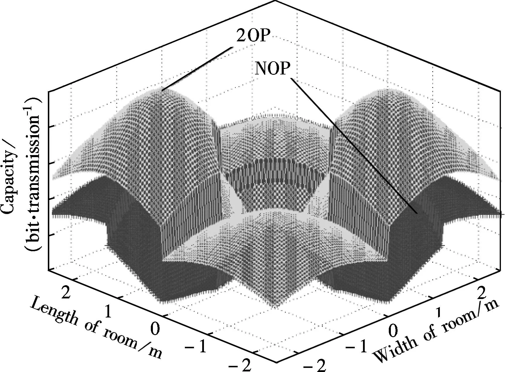
Fig.5 Channel capacity of 2OP and NOP
In what follows, we consider the BER performance of the system. The BER performance is significantly improved by using OPs over NOPs, especially at the center and interference areas of the room, as shown in Fig.6 and Fig.7. The theoretical and numerical results of 4OP, 2OP and NOP are compared with diagonals and sides of the room, as shown in Fig.6 and Fig.7. It is clear that the numerical and theoretical responses are almost identical. As discussed in the case of 2OP, the diagonal cells share the same pulse; therefore, the interference only occurs between diagonal cells. However, the side cells use OPs, so the BER responses of 2OP and 4OP in Fig.7 are identical. The maximum BER is in the center of the room because the equal power is received from all cells. The identical response for OPs and NOPs are at the corners of the room. The corners of the room are not affected by ICI. ICI occurs when a zero transmitted by the principle cell is falsely identified as the one from other cells. ICI increases with the increase of SNR; therefore, the difference between OPs and NOPs is increased with high SNRs, as shown in Fig.8.
Generally, a better BER performance can be achieved at a high SNR. However, due to interference, the performance of NOPs does not improve significantly. Fig.8 depicts the scenarios when the SNR are 56, 60, 65, and 68 dB along with the diagonals of the room. The results show that with the high SNR, the proposed scheme is more effective.
Simulation results show that the proposed scheme obtains a better BER at the expense of an increased bandwidth. Compared 2OP with 4OP, the 2OP requires low bandwidth and provides comparatively less capacity, and it also has worse BER performance. Hence, the proposed scheme eliminates the interference from LOS as well as from the diffuse path.
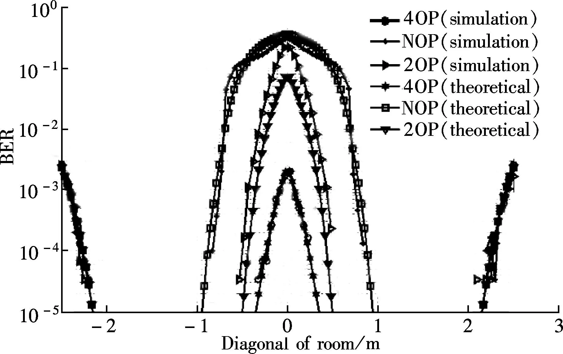
Fig.6 BER vs. diagonal of the room (SNR=66 dB)
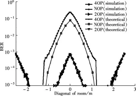
Fig.7 BER vs. length of the room (SNR=66 dB)
4Conclusion
We investigate the BER and capacity performances of our recently proposed scheme in the indoor VLC system under multi-cell environments. The inter-cell interference is eliminated by OPs. In this scheme, the BER and capacity performances are improved. A method to improve the system performance by utilizing high bandwidth pulses is analyzed.
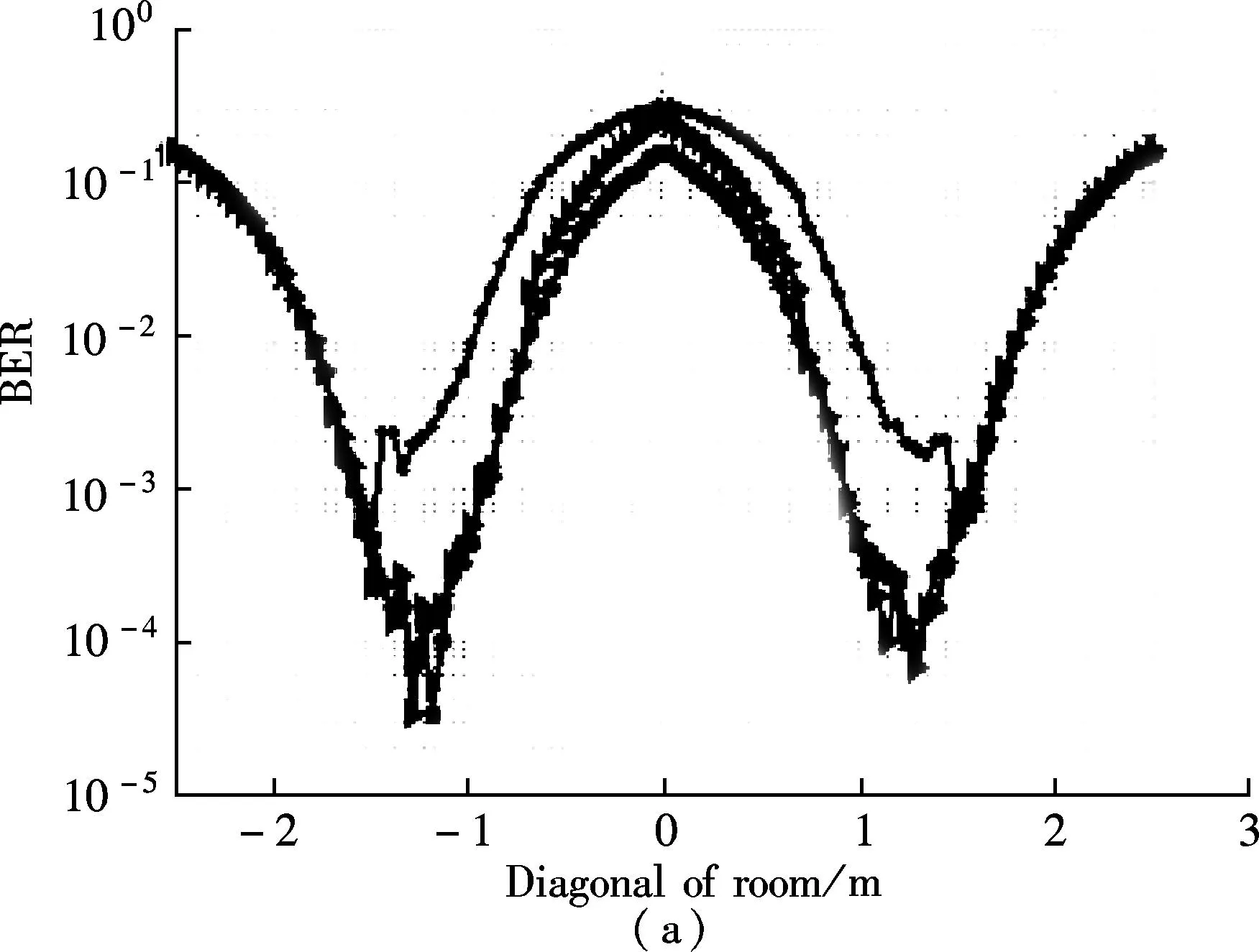
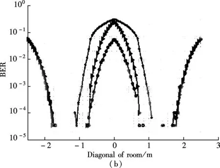
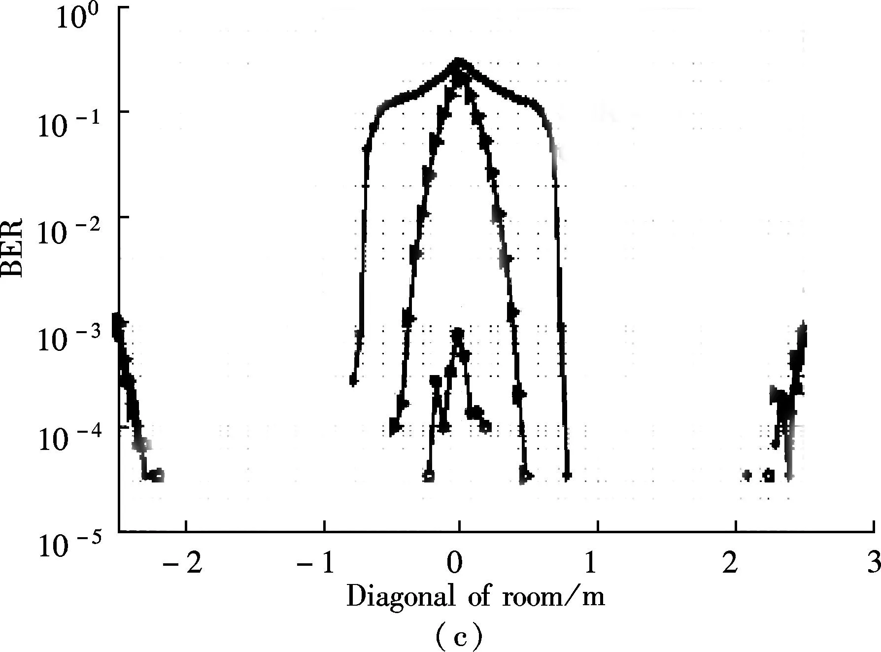
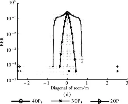
Fig.8 ER vs. diagonal of the room under different SNRs. (a) SNR=56 dB; (b) SNR=60 dB;(c) SNR=65 dB;(d) SNR=68 dB
Simulation results show that at a high SNR, the proposed scheme is more effective in the interference areas of the room. Simulation and theoretical results show that the proposed scheme removes the limitation of the FOV of the transmitter and covers the whole area of the room as well as reducing ICI. When the number of OPs increases, high bandwidth LEDs are required, which can be managed by reusing OP at a certain distance and significant improvements of the capacity and BER performances can be obtained.
References
[1]Komine T, Nakagawa M. Fundamental analysis for visible-light communication system using LED lights[J].IEEETransactionsonConsumerElectronics, 2004, 50(1): 100-107.
[2]Zeng L, O’Brien D, Minh H, et al. High data rate multiple input multiple output (MIMO) optical wireless communications using white LED lighting[J].IEEEJournalonSelectedAreasinCommunications, 2009, 27(9): 1654-1662.
[3]Rahaim M, Little T. SINR analysis and cell zooming with constant illumination for indoor VLC networks [C]//The2ndInternationalWorkshoponOpticalWirelessCommunications(IWOW). Newcastle Upon Tyne, UK, 2013: 20-24.
[4]Wang Z, Yu C, Zhong W D, et al. Performance of a novel LED lamp arrangement to reduce SNR fluctuation for multi-user visible light communication systems[J].Opticsexpress, 2012, 20(4): 4564-4573.
[5]Guerra-Medina M, Gonzalez O, Rojas-Guillama B, et al. Ethernet-OCDMA system for multi-user visible light communications[J].ElectronicsLetters, 2012, 48(4): 227-228.
[6]Wu Z, Little T. Network solutions for the line-of-sight problem of new multi-user indoor free-space optical system[J].IETCommunications, 2012, 6(5): 525-531.
[7]Chen J, Hong Y, Wang Z. Performance of precoding multi-user MIMO indoor visible light communications [C]//IEEEPhotonicsConference(IPC),WG4. Reston, USA, 2013: 541-542.
[8]Spencer Q H, Swindlehurst A L, Haardt M. Zero-forcing methods for downlink spatial multiplexing in multiuser MIMO channels[J].IEEETransactionsonSignalProcessing, 2004, 52(2): 461-471.
[9]Spencer Q H, Peel C B, Haardt M. An introduction to the multi-user MIMO downlink[J].IEEECommunicationsMagazine, 2004, 42(10): 60-67.
[10]Ali A Y, Zhang Z, Zong B. Pulse position and shape modulation for visible light communication system [C]//InternationalConferenceonElectromagneticsinAdvancedApplications(ICEAA). Palm Beach, Aruba, 2014:546-549.
[11]Uddin M S, Cha J S, Kim J Y, et al. Mitigation technique for receiver performance variation of multi-color channels in visible light communication[J].Sensors, 2011, 11(6): 6131-6144.
[12]Ali A Y, Zhang Z. Received power based area estimation for indoor visible light communication[C]//InternationalConferenceonInformation&IntelligentSystems(ICIIS). Sousse,Tunisia, 2013:1-8.
doi:10.3969/j.issn.1003-7985.2015.04.002
杂志排行
Journal of Southeast University(English Edition)的其它文章
- Modified particle swarm optimization-based antenna tiltangle adjusting scheme for LTE coverage optimization
- Distribution algorithm of entangled particles for wireless quantum communication mesh networks
- Kernel principal component analysis networkfor image classification
- CFD simulation of ammonia-based CO2 absorption in a spray column
- Simulation and performance analysis of organic Rankine cycle combined heat and power system
- Experimental investigation on heat transfer characteristics of a new radiant floor system with phase change material
