Improving the corrosion resistance of AZ91D magnesium alloy through reinforcement with titanium carbides and borides
2015-02-16RoertAkid
*Roert Akid
aEgyptian Armed Force,Kobbry Elkobba,Cairo,Egypt
bSchool of Materials,The University of Manchester,UK
Improving the corrosion resistance of AZ91D magnesium alloy through reinforcement with titanium carbides and borides
Mohamed Gobaraa,*,Mohamed Shamekha,Robert Akidb
aEgyptian Armed Force,Kobbry Elkobba,Cairo,Egypt
bSchool of Materials,The University of Manchester,UK
A composite consisting of magnesium matrix reinforced with a network of TiC-Ti2AlC-TiB2particulates has been fabricated using a practicalin-situreactive infltration technique.The microstructural and phase composition of the magnesium matrix composite(R-Mg)was investigated using SEM/EDS and XRD.The analyses revealed the complete formation of TiC,Ti2AlC and TiB2particles in the magnesium matrix.Comparative compression tests of R-Mg and AZ91D alloy showed that the reinforcing particles improve the mechanical properties of Mg alloy.EIS and potentiodynamic polarization results indicated that the reinforcing particles signifcantly improve the corrosion resistance of the reinforced alloy in 3.5%NaCl solution.
Magnesium composite;EIS;Compression test;Passivity
1.Introduction
Magnesium alloys are receiving increasing attention as potential applications in the automotive and aerospace sectors, due to their light weight.Magnesium is the lightest structural metal,being 35%lighter than aluminium and over four times lighter than steel[1].However,the application of magnesium and magnesium alloys in automotive and aerospace applications has been limited due to its rapid loss of strength with increasing temperature,low elastic modulus,low wear resistance at elevated temperatures,poor creep resistance,high coeffcient of thermal expansion,and poor corrosion resistance [2,3].Reinforcement of Mg with suitable ceramic particles such as TiC and TiB2can compensate for some of the above mentioned shortcomings[4].This facilitates its use in different applications requiring high specifc strength,high specifc stiffness,high wear resistance and good elevated temperature creep properties[5-10].
Different techniques have been used to fabricate Mg matrix composites reinforced with in-situ TiC and TiB2particles, such as self-propagating high temperature synthesis(SHS)and re-melting and dilution[3,7].In these techniques,a metal powder such as Al was added to Ti-B4C preform in fabricating TiB2-TiC/Mg matrix composites in order to promote the reaction between Ti and B4C.However,high Al content leads to limited ductility of the matrix because of the formation of the interdentritic grain boundary phase Mg17Al12[11].
In different applications,notably in the automotive industry,compression properties of Mg matrix composites are very important for the load carrying structural components, especially at elevated temperature[12].
Mg is a very electronegative metal,having an electrode potential around-1.5 V vs.SCE[13].This high negative potential combined with the formation of a non-compact,nonprotective oxide layer,when exposed to electrolytes as benignas water,leads to severe corrosion of this metal.Moreover, impurities and second phase particles act as active cathodic sites that accelerate corrosion of the magnesium matrix [14,15].
In order to increase the potential use of Mg and Mg alloys in various applications,engineers and designers are working to improve the magnesium corrosion resistance through modifcation of alloy chemistry and by improved surface protection technologies.In addition,improved mechanical properties may be achieved by microstructural engineering[14,16,17] and/or the addition of different alloying elements[18-26].
In this study,the corrosion behaviour of an in-situ reactive infltration fabricated Mg matrix composite is investigated in aerated 3.5%NaCl corrosive solution and the results are compared with those of a commercial Mg alloy AZ91D.
2.Experimental
The materials used in this work are a Mg alloy AZ91D and a Mg matrix reinforced with a network of TiC-Ti2AlC-TiB2particulates(R-Mg).The starting powders for synthesizing RMg are Ti(-325 mesh,99.61%purity,Alfa Aesar Co.),B4C (99%purity,<10 μm particle size,Alfa Aesar Co.),and MgH2(98%purity,<59 μm particle size,Alfa Aesar Co.)powders. Titanium and boron carbide powders are at a(3:1)molar ratio corresponding to that of stoichiometric TiC and TiB2.
In the processing of the R-Mg,the molten AZ91D alloy infltrates a preform of 90 wt.%(3Tip-B4Cp)+10 wt.% MgH2by capillary forces at a processing temperature of 900°C and 1.5 h hold time.Experiments were conducted in an electric furnace under argon gas atmosphere (purity=99.999%).The samples were allowed to cool to room temperature in the furnace.Additional details related to synthesis conditions,relative concentrations and mechanism of preparation of the reinforced particles are available elsewhere[27,28].
The‘apparent’density of R-Mg was measured using the water absorption method based on Archimedes principle (ASTM C20-00)[29].The microstructure and the phase analysis of the R-Mg samples were investigated by using scanning electron microscopy(SEM,Philips XL30 FEG) equipped with an energy dispersive X-ray spectroscopy(EDS) analyzer and X-ray electron probe microanalysis(EPMA).XRay diffraction(XRD)using X'Pert PRO X-ray diffractometer (PANalytical Inc.)was used to investigate the crystalline structure.It is important to note that silicon is added to the powder sample during the XRD analysis as an internal standard to correct any systematic error.
Mechanical compression tests were performed on asreceived AZ91D alloy and the R-Mg composite according to ASTM E9-89a[30].Cylindrical specimens 12.7 mm in diameter and 25 mm in height were used for the test. Compression tests were performed on an MTS 809 machine, with a 250 kN load capacity at room temperature with a crosshead speed of 0.5 mm/min.Note:no barrelling was observed.
AZ91D alloy samples(obtained from Q-panels)were cleaned with deionised water followed by rinsing with acetone and then left to dry for 30 min at 60°C.The samples (25 mm×25 mm×1 mm)then were cooled before corrosion tests were conducted at room temperature.R-Mg specimens were machined to cuboids with dimensions 10 mm×10 mm×25 mm and then cleaned according to the above cleaning procedure.
Corrosion tests were carried out in a three-electrode type cell using a saturated calomel electrode(SCE)reference electrode,a platinum counter electrode and the sample as the working electrode.The cyclic potentiodynamic polarization tests were performed using an initial delay time at steady opencircuit potential(OCP)for 60 min to stabilize the surface.The polarization scan started from 100 mV below OCP i.e.from cathodic to anodic at a rate of 1 mV/s.The sweep direction was reversed to the cathodic direction when the current density reached 2 mA/cm2.The test is stopped when the hysteresis loop closes or the corrosion potential is reached[31].
Electrochemical impedance spectroscopy(EIS)measurements were obtained at the measured OCP values applying ±10 mV perturbation in the frequency range from 1×10⁵to 10-2Hz.Electrochemical corrosion measurements were performed separately in 3.5%NaCl solution at room temperature, naturally aerated,with a Gamry reference 600 instrument.The solution was renewed every three days.The experimental results of the impedance were analyzed in terms of an equivalent circuit using nonlinear least squares ft technique provided by the Gamry software.
3.Results and discussion
3.1.Microstructure
Fig.1 shows the XRD spectra of the R-Mg matrix composite.The results confrm the complete formation of the reinforcing phases Ti2AlC,TiCxand TiB2inside the magnesium matrix.No residual intermediate phases(such as TiB) have been observed.The formation of the ternary compound, Ti2AlC,has been confrmed by comparing the XRD pattern ofthe fabricated composite sample with that of Ti2AlC obtained from Pearson's crystal database[32].It is important to note that magnesium and magnesium oxide have been produced during the synthesis of R-Mg due to reduction of MgH2and then interaction of Mg with oxygen respectively[33].
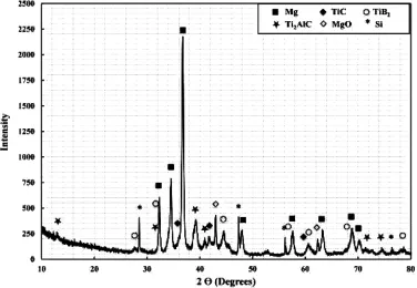
Fig.1.XRD spectra of the R-Mg fabricated at 900°C for 1.5 h using 10 wt.% MgH2-90%(3Ti-B4C).
EPMA was used to analyze the distribution of the in-situ reaction products;TiCx,TiB2,and infltrated magnesium as shown in Fig.2.The microstructure of the composite shown in Fig.2 reveals a relatively uniform distribution of reinforcing phases Ti2AlC,TiCxand TiB2,as a network in the R-Mg. Furthermore,the EPMA maps reveal the existence of Al not only inside the Mg matrix but also in the Mg-free regions.This indicates that the ternary compound(Ti2AlC)is relatively uniformly distributed in the network of the reinforcing phases. The overlap between titanium,boron and carbon is clearly observed proving the presence of the reinforcing phases Ti2AlC,TiC and TiB2.Moreover,the overlap between titanium,aluminium and carbon in the region of concentrated aluminium reveals three distinct regions from the interface to the core where Ti increases in the direction of the core while the concentration of Al increases in the opposite direction, indicating the reinforced particle of Ti2AlC is formed by diffusion of aluminium though titanium particles.
3.2.Characterization of R-Mg
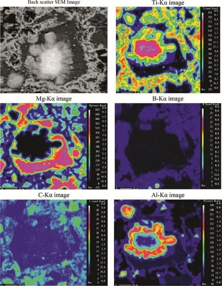
Fig.2.EPMA of the R-Mg fabricated at 900°C for 1.5 h using 10 wt.%MgH2-90%(3Ti-B4C).
The results of the density and room temperature compressive property measurements reveal that the density of the R-Mg liesat a value somewhere between the density of the AZ91D alloy and that of the reinforcing phases.The density of R-Mg (2800 kg m-3)is nearly 155%and 50%of that of the AZ91D alloy and TiC,respectively.Typical compression behaviour of theR-Mg,comparedwith thatofthe unreinforced AZ91Dalloy, isshowninFig.3.TheresultsshowthattheR-Mgmanufactured in this study exhibits higher modulus and compressive strength comparedwiththatoftheunreinforcedAZ91Dmatrix,whilethe ductility is reduced.The compressive strength and Young's modulus of the R-Mg increased by nearly 300%and 320%, respectively while the ductility decreased by typically 71% comparedwiththatoftheunreinforcedAZ91Dalloy.Ingeneral, theincreasedstrengthofthecompositeisduetotheformationof the reinforcing phases where the dispersion of fne and hard particles into the matrix blocks the dislocation motion and thus strengthens the material.
3.3.Corrosion performance of the AZ91D alloy and RMg
AZ91D is a two-phase alloy,where the second phase is not continuous therein reducing the ability for the second phase to provide a passive barrier[34].The corrosion behaviour of AZ91D alloy in a corrosive solution such as 3.5%NaCl solution is governed by the volume of the alpha-Mg matrix and the composition and the distribution of the other phases.The alpha-Mg matrix has a corrosion rate signifcantly greater than that of beta phase,Mg17All2M,in this corrosive solutions[35]. The second phase acts as micro-cathodes with respect to alpha-Mg anode forming micro-scale localized galvanic cells which signifcantly accelerate the corrosion rate of adjacent alpha-Mg matrix[34].
3.3.1.Potentiodynamic polarization results
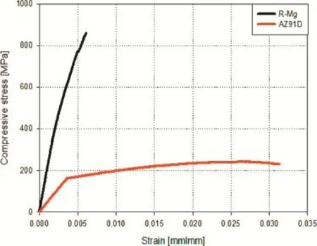
Fig.3.Compression stress-strain curves of(a)AZ91D alloy and(b)R-Mg composite.
AZ91D alloy is susceptible to localized corrosion,notably pitting corrosion;accordingly cyclic polarization tests were conducted to evaluate the pitting tendencies of both R-Mg and AZ91D alloys in a 3.5%NaCl solution.The cyclic potentiodynamic polarization curve obtained for both alloys immersed in solution is shown in Fig.4.AZ91D alloy does not exhibit passivity with the anodic branch of the AZ91D sample showing continuous active dissolution of the metal until the current density reaches the value of 2 mA/cm2whereupon the potential is reversed.The curve shows a positive hysteresis, with pitting potential located approximately at the same position of that of corrosion potential.In addition,the repassivation potential is more active than the corrosion potential (OCP)with a corrosion current density of 0.76 mA/cm2and the curve shows signifcant hysteresis,in comparison to the Mg-R sample,indicating nucleation and growth of pitting [36].
The cyclic potentiodynamic polarization of the R-Mg sample(Fig.4)shows negative hysteresis.In comparison,the corrosion current density of the R-Mg sample is one order of magnitude lower than that of AZ91D sample at 0.07 mA/cm2. Further,the polarisation curve of the R-Mg sample exhibits a corrosion potential(-1087 mV vs.SCE)that is higher than that of AZ91D sample(-1576 mV vs.SCE).In addition the slope of the anodic branch of the R-Mg sample(803 mV/dec.) is much greater than that of the AZ91D sample(214 mV/dec.), implying a higher corrosion resistance for the R-Mg sample. The surface morphology of both samples will be discussed later.
3.3.2.Electrochemical impedance results
Using potentiodynamic polarization technique for measuring corrosion rate is semi-quantitative as the rate of corrosion of magnesium alloys changes with the immersion time[37].Consequently,EIS was applied to evaluate the corrosion performance of both AZ91D and R-Mg alloys.EIS was used at an open-circuit potential with the alloys immersed in naturally aerated 3.5%NaCl solution.Nyquist plots,as a function of immersion time for the AZ91D alloy are shown in Fig.5.The plots do not illustrate perfect semicircles,asexpected from theory,which may be attributed to the inhomogeneities of the surface such as formation of porous layers and/or surface roughness[38].
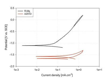
Fig.4.Cyclic potentiodynamic polarization curves for AZ91 and R-Mg in aerated 3.5%NaCl solution at room temperature.
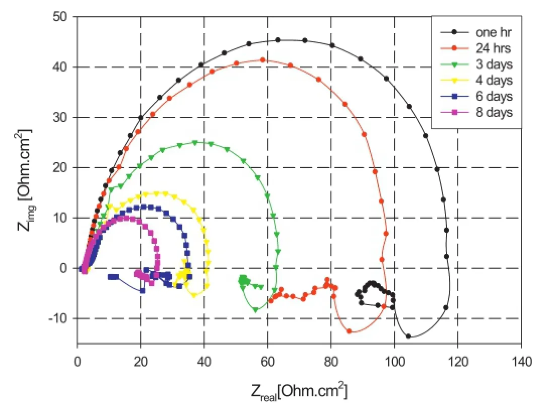
Fig.5.Nyquist plots of AZ91 in aerated 3.5%NaCl solution at room temperature.
Two phenomena are observed from the fgure:frstly,the alloy exhibits the same trend throughout the immersion period. Secondly,the magnitude of the semi-circles decreases with immersion time.It can be observed that,the Nyquist plot contains a capacitive loop at high to medium frequency and an inductance loop at low frequency which indicates that there are two processes taking place during immersion in solution. The frst process represented by the capacitive loop in the high-medium frequency region is related to the charge transfer resistance and the electric double layer capacitance.With prolonged immersion,the semicircle diameter decreases by about one order of magnitude over an 8-day period.This decrease of capacitive behaviour refects the decrease of corrosion resistance of the alloy that may be assigned to the formation of corrosion products[37].The second process is represented by the low frequency inductive loop,which may be related to corrosion processes at the metal/solution interface where interactions of water molecules and Cl-with the metal surface take place[39].This interaction can be described by either,or both,the instability of the electrode surface(Cl-penetration and adsorption),and the formation of a magnesium hydroxide layer[40].Also,it can be seen that the size of the inductive loop decreases with the immersion time which may be related to the formation of a non-protective layer of magnesium hydroxide and/or chloride that hinder the interaction between the metal surface and the corrosive solution.
Visual inspection reveals that a vigorous reaction of the magnesium surface takes place directly after immersion in 3.5%NaCl solution,which is related to water reduction and evolution of hydrogen gas.It was observed that this reaction continued during the following 8 days of immersion.Additionally,a white gelatinous insoluble precipitate appeared after 3 days of immersion in the electrolyte,which continued to develop with increased immersion time.The composition of the precipitate is considered to be likely that of magnesium hydroxide and/or chloride[33].
On the basis of these observations,the following electrochemical reactions are considered to take place on the magnesium surface in aqueous NaCl solution.

As shown in reaction(1),the anodic reaction comprises the oxidation of magnesium forming magnesium(II)ion where the cathodic reaction is water reduction(reaction(2)).Finally the magnesium ion reacts with hydroxyl ions producing insoluble magnesium hydroxide as shown in reaction(3) [37,41].
In the presence of high chloride ion concentration,magnesium hydroxide will transform to insoluble magnesium chloride[42].

The precipitate of corrosion products that thicken with immersion time delays the progressive dissolution of magnesium[43].
From the above discussion,when magnesium comes in contact with an aqueous solution,magnesium hydroxide and/ or chloride are formed on the magnesium surface,which serves as a protective layer.However,this layer cannot protect the alloy in the presence of a corrosive medium containing Cl-,due to the porous nature of this layer[44].
To further elucidate the corrosion mechanism of AZ91D in 3.5%NaCl solution,SEM analysis was conducted following immersion in 3.5%NaCl solution for 24 h and 8 days as shown in Fig.6.From Fig.6a it is clear that corrosion has occurred over the entire metal surface with individual shallow pitting being observed at sites of intermetallic particles.After 8 days of immersion,Fig.6b,the corrosion becomes intensive exhibiting localized corrosion at intermetallic particles,which are cathodic with respect to magnesium[45],forming a microgalvanic cell with the surrounding alpha magnesium matrix. When the magnesium matrix surrounding the intermetallic particles dissolves,these particles detached from the matrix leaving vacant sites on the surface[37].
The Nyquist for R-Mg in 3.5%NaCl solution is shown in Fig.7.The fgure shows a capacitive peak at high to intermediate frequency range and an inductive peak at a low frequency range after one hour of immersion.However,for following measurements(24 h to 22 days)this inductive peak is not present.The low frequency region represents the interfacial processes which occur between the metal surface and the corrosive solution,indicating that an interaction at the metal/solution interface takes place in the frst few hours of immersion.It is believed that the inductive loop in the low frequency range is an indication of the corrosion of magnesium[46-49].Therefore the disappearance of the inductive loop suggests that a more protective flm is formed on thesurface[46].Moreover,Fig.7 shows that,the Nyquist curves transform from a resistive behaviour during the frst 24 h of immersion to a capacitive behaviour during the remaining immersion time.This capacitive behaviour continues to increase with immersion time,which may be attributed to the formation of a passive layer.

Fig.6.SEM images of AZ91 sample after immersion for(a)24 h and(b)8 days in aerated 3.5%NaCl solution at room temperature.
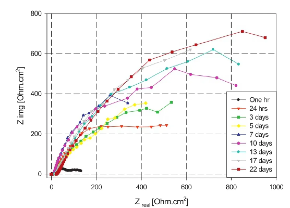
Fig.7.Nyquist plots of R-Mg in aerated 3.5%NaCl solution at room temperature.

Fig.8.Phase angle response of R-Mg in aerated 3.5%NaCl solution at room temperature.
Fig.8 presents Phase angle plots of the R-Mg alloy where it is seen that there is one time constant with an inductive loop for the sample directly after immersion(1 h);the time constant is at medium frequency range and the inductive loop is at low frequency range.The time constant represents the charge transfer resistance and the electric double layer capacitance, whilst the inductive peak is related to the corrosion process taking place at the metal/solution interface.
After 24 h of immersion,the phase angle curves show a broad peak,at≈0.3 Hz,which not only shifts from medium to low frequencies,but also increases to approach 70°.In addition,this peak becomes much broader with increasing time of immersion.The large phase angle peak could be indicative of two processes taking place during immersion[50].The time constant at medium frequency represents the charge transfer resistance and the electric double layer capacitance,whereas the low frequency range time constant represents the formation of a protective layer that increases the corrosion resistance of R-Mg sample.
This capacitive behaviour is typical of passive materials suggesting that a stable flm is formed on R-Mg surface in NaCl corrosive solution[50].This is consistent with the results determined by potentiodynamic polarization tests.
Physical observation of the R-Mg sample showed that a strong reaction occurs directly after immersion in NaCl solution.This reaction completely vanished after one day of immersion and neither sign of corrosion products nor precipitation on the metal surface were observed.This reaction may be related to the reduction of water on the magnesium surface(cathodic reaction)that produces hydrogen gas as shown in reaction(1).The anodic reaction is the oxidation of magnesium at the metal surface leaving the reinforcement network matrix,which has better corrosion resistance.
From the above discussion,it can be concluded that,the RMg has a different behaviour than that of AZ91D alloy;it seems to have a passivating behaviour.
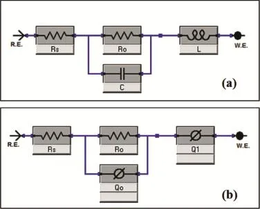
Fig.9.Equivalent circuits used for numerical ftting of the EIS experimental data for the R-Mg sample;(a)before 24 h and(b)after 24 h of immersion in aerated 3.5%NaCl solution at room temperature.
The EIS results were analyzed by ftting EIS data to‘equivalent circuit’models,as shown in Fig.9.In Fig.9a,Rsrepresents the solution resistance between the alloy and the counter(platinum)electrode,Cis the double layer capacitance,Rois the polarization resistance and theLis an inductive loop related to instability due to dissolution of magnesium from the surface of the R-Mg alloy.This circuit represents the R-Mg during the frst 24 h of immersion in 3.5%NaCl solution.The modelling circuit of R-Mg during the remaining period of immersion is presented in Fig.9b,whereRsis the solution resistance between the alloy and the counter(platinum)electrode,Rois the polarization resistance,QoandQ1are the constant phase elements(CPEs)for the double layer and the formed passivating layer on the R-Mg surface respectively.The results of ftting the experimental data to these circuits are presented in Fig.10.
Fig.10 shows that directly after immersion the sample in 3.5%NaCl solution,the R-Mg sample exhibits low resistance and high capacitance indicating a corrosion process,notably the dissolution of magnesium from the surface via cathodic reduction of water.It is observed that during the frst 3 days of immersion,the sample shows signifcant increase in the resistance(R1)from 106 to 890 Ohm cm2and signifcant decrease in the capacitance(Qo)from 0.5× 10⁻³to 10-5F cm-2.However,during the remaining time the sample is immersed,the value ofR1slightly increases from 890 to 1363 Ohm cm2(i.e.473 Ohm cm2over 19 days).In addition, the value ofQoexhibits a stable behaviour that varies within less than one order of magnitude.The fgure also shows that the value ofQ1of the layer formed on the magnesium surface offers stability to the alloy over 22 days of immersion period that it varies within one order of magnitude(between 10-2and 10-3F cm-2)as shown in Fig.10.
From the above results,the protective layer appears relatively stable,as represented by the capacitance values and the increase in the resistive behaviour suggests the system to be of a passivating type.
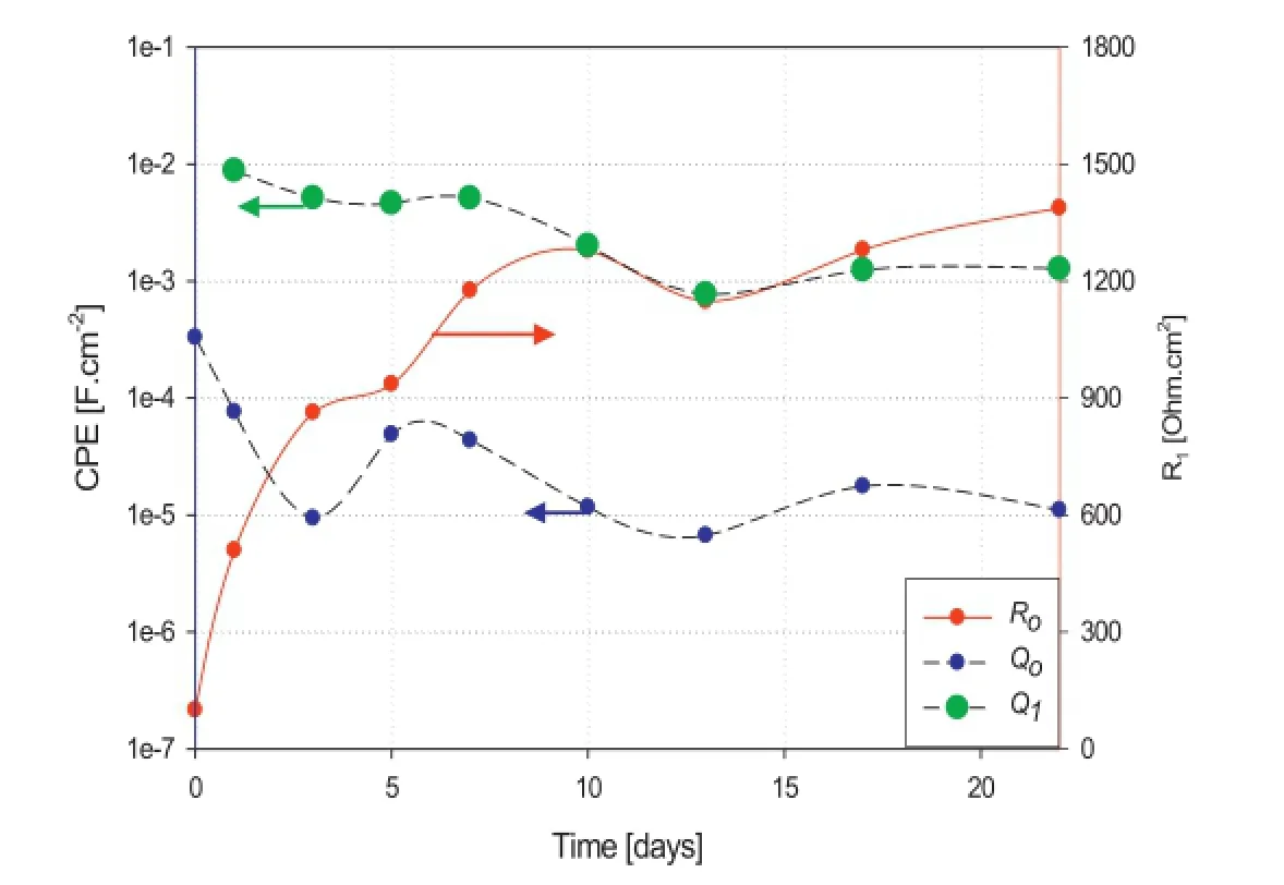
Fig.10.Change of constant phase elements of double layer capacitance(Qo), passivating layer capacitance(Q1)and charge transfer resistance(Ro)of R-Mg sample with time of immersion in 3.5%NaCl solution.
On exposure of the composite sample,R-Mg,in the 3.5% sodium chloride solution(Fig.10)a signifcant increase in the corrosion potential was observed,as shown in Fig.11.The electrode potential is continuously increasing to more noble potentials during the frst three days of immersion then the potential becomes typically stable which indicates the formation of a stable protective layer that improved corrosion resistance of the prepared composite alloy,R-Mg.
SEM images of the R-Mg sample,before and after 22 days of immersion in 3.5%NaCl solution,are shown in Fig.12. Fig.12a shows that the sample contains alpha magnesium(see arrows),as previously confrmed by XRD(Fig.1),however, these alpha-Mg areas disappear during immersion in thecorrosive solution,as shown in Fig.12b.This observation was confrmed by EDX-spot analysis as shown in Fig.12c and d where the magnesium peak dramatically decreases after immersion in the corrosive solution for 22 days.

Fig.11.Change of corrosion potential of R-Mg sample with immersion time in aerated 3.5%NaCl solution at room temperature.

Fig.12.SEM image of R-Mg sample(a)before and(b)after immersion in 3.5%NaCl solution,(c)EDX-spot analysis before immersion and(d)after 22 days of immersion in 3.5%NaCl solution.
From the above discussion,it can be concluded that the improvement in corrosion performance of R-Mg(compared to AZ91D alloy)is related to the dissolution of alpha magnesium from the R-Mg surface during frst few hours of immersion in the corrosive solution leaving a surface rich in titanium carbides and borides,which have improved corrosion performance over that of magnesium alloy AZ91D.This can be confrmed by the increase of corrosion potential,potentiodynamic polarization response and EIS results of R-Mg with immersion time.
The overall observation is that reinforcing magnesium with titanium carbides and borides particulates using in-situ reactive infltration technique improves the corrosion resistance in aerated 3.5%NaCl corrosive medium compared to the AZ91D alloy.
4.Conclusions
1.Reinforcing the AZ91D alloy with a network of TiC, Ti2AlC,and TiB2particulates increases the mechanical properties;notably compressive strength by 300%and Young's modulus by 320%.Furthermore,the density of the composite increased by 155%compared to that of the AZ91D alloy.
2.EPMA revealed a uniform distribution of reinforcing phases within the composite matrix R-Mg.
3.Potentiodynamic polarization indicted that AZ91D is susceptible to localized corrosion and the composite alloy showed a passivating behaviour.
4.Polarisation resistance values obtained from EIS analysis indicate that the composite alloy,R-Mg,has high activity during the frst days of immersion in NaCl corrosive solution due to initial dissolution of alpha magnesium from the R-Mg surface leaving a more corrosion resistance reinforced matrix(titanium carbides and borides).
Acknowledgements
The authors would like to thank the Egyptian Armed Force for providing access to the testing facilities to undertake this project.Moreover,the authors would also like to thank Dr. Magdy Ibrahim for his invaluable advice during the conducting SEM images and samples analysis.
[1]M.Kulekci,Int.J.Adv.Manuf.Technol.39(2008)851-865.
[2]B.L.Mordike,T.Ebert,Mater.Sci.Eng.A 302(2001)37-45.
[3]Z.Xiuqing,W.Haowei,L.Lihua,T.Xinying,M.Naiheng,Mater.Lett. 59(2005)2105-2109.
[4]C.Fang,L.Wang,H.Hao,X.Zhang,J.Mater.Process.Technol.214 (2014)551-555.
[5]S.Hassan,M.Gupta,Mater.Res.Bull.37(2002)377-389.
[6]H.Wang,Q.Jiang,X.Li,J.Wang,Q.Guan,H.Liang,Mater.Res.Bull. 38(2003)1387-1392.
[7]B.Ma,H.Wang,Y.Wang,Q.Jiang,J.Mater.Sci.40(2005)4501-4504.
[8]J.Dai,Y.Song,R.Yang,J.Alloys Compd.595(2014)142-147.
[9]Y.Hu,L.Rao,Trans.Nonferrous Met.Soc.China 22(2012)2659-2664.
[10]M.J.Shen,X.J.Wang,C.D.Li,M.F.Zhang,X.S.Hu,M.Y.Zheng, K.Wu,Mater.Des.54(2014)436-442.
[11]K.U.Kainer,Magnesium Alloys and Technology,Wiley VCH,Weinheim,Germany,2003.
[12]W.Cao,C.Zhang,T.Fan,D.Z.Di Zhang,Mater.Trans.49(2008) 2686-2691.
[13]H.Wang,R.Akid,M.Gobara,Corros.Sci.52(2010)2565-2570.
[14]G.Song,A.Atrens,Adv.Eng.Mater.5(2003)837-844.
[15]E.-S.Sherif,A.A.Almajid,Int.J.Electrochem.Sci.6(2011) 2131-2148.
[16]E.Ghali,Magnesium and Magnesium Alloys,Uhlig's Corrosion Handbook,John Wiley&Sons,New York,2000,p.793.
[17]S.Candan,M.Unal,E.Koc,Y.Turen,E.Candan,J.Alloys Compd.509 (2011)1958-1963.
[18]Y.Guangyin,S.Yangshan,Ding Wenjiang,Scr.Mater.43(2000) 1009-1013.
[19]Y.Guangyin,S.Yangshan,D.Wenjiang,Mater.Sci.Eng.A 308(2001) 38-44.
[20]D.Wenwen,S.Yangshan,M.Xuegang,X.Feng,Zhu Min,W.Dengyun, Mater.Sci.Eng.A 356(2003)1-7.
[21]W.Guohua,Y.Fan,G.Hongtao,Z.Chunquan,Z.Y.Ping,Mater.Sci. Eng.A 408(2005)255-263.
[22]W.Zhou,Naing Naing Aung,Yangshan Sun,Corros.Sci.51(2009) 403-408.
[23]B.H.Kim,S.W.Lee,Y.H.Park,I.M.Park,J.Alloys Compd.493(2010) 502-506.
[24]F.Wang,Y.Wang,P.-l.Mao,B.-y.Yu,Q.-y.Guo,Trans.Nonferrous Met. Soc.China 20(2010)311-317.
[25]N.D.Nam,J.Mag.Alloys 2(2014)190-195.
[26]K.Suresh,K.P.Rao,Y.V.R.K.Prasad,N.Hort,K.U.Kainer,Trans. Nonferrous Met.Soc.China 23(2013)3604-3610.
[27]M.P.M.Shamekh,M.Medraj,Adv.Mater.Res.409(2012)215-220.
[28]M.Shamekh,M.Pugh,M.Medraj,Adv.Eng.Mater.(2013).
[29]ASTM,C20-00,ASTM,West Conshohocken,PA,USA,2000.
[30]ASTM,A.E9-89a,ASTM,West Conshohocken,PA,USA,1989.
[31]F.Gui,C.S.Brossia,in:L.Yang(Ed.),Techniques for Corrosion Monitoring,Woodhead Publishing Limited,Cambridge,England,2008.
[32]H.A.Putz,Pearson's Crystal Data.
[33]P.Patnaik,Handbook of Inorganic Chemicals,McGraw-Hill Companies, New York,USA,2003.
[34]M.L.Zhiming Shi,Andrej Atrens,Corros.Sci.52(2010)579-588.
[35]M.Jonsson,D.Persson,C.Leygraf,Corros.Sci.50(2008)1406-1413.
[36]B.Zaid,D.Saidi,A.Benzaid,S.Hadji,Corros.Sci.50(2008) 1841-1847.
[37]A.Pardo,M.C.Merino,A.E.Coy,R.Arrabal,F.Viejo,E.Matykina, Corros.Sci.50(2008)823-834.
[38]M.A.Amin,M.M.Ibrahim,Corros.Sci.53(2011)873-885.
[39]H.Gao,Q.Li,F.Chen,Y.Dai,F.Luo,L.Li,Corros.Sci.53(2011) 1401-1407.
[40]C.Cao,J.Zhang,Introduction of Electrochemical Impedance Spectroscopy,Science Press of China,Beijing,2002.
[41]A.Dhanapal,S.Rajendra Boopathy,V.Balasubramanian,J.Alloys Compd.523(2012)49-60.
[42]M.Jamesh,S.Kumar,T.Sankara Narayanan,Corros.Sci.53(2011) 645-654.
[43]H.Meifeng,L.Lei,W.Yating,T.Zhixin,H.Wenbin,Corros.Sci.50 (2008)3267-3273.
[44]G.Song,The Corrosion and Protection of Magnesium Alloys,Chemical Industry Press of China,Beijing,2006.
[45]R.-c.Zeng,J.Zhang,W.-j.Huang,W.Dietzel,K.Kainer,C.Blawert, W.Ke,Trans.Nonferrous Met.Soc.China 16(2006)s763-s771.
[46]C.C.Tao Zhang,Yawei Shao,Guozhe Meng,Fuhui Wang,Xiaogang Li, Chaofang Dong,Electrochim.Acta 53(2008)7921-7931.
[47]J.Chen,J.Wang,E.Han,J.Dong,W.Ke,Electrochim.Acta 52(2007) 3299-3309.
[48]C.L.Yunchang Xin,Wenjun Zhang,Jiang Jiang,GuoyiTang, Xiubo Tian,Paul K.Chu,J.Electrochem.Soc.155(2008)C178-C182.
[49]L.Li,F.Pan,J.Lei,Corrosion and Surface Treatments,2011.Available from: http://www.intechopen.com/books/magnesium-alloys-corrosionand-surface-treatments/environmental-friendly-corrosion-inhibitors-formagnesium-alloys.
[50]A.Fekry,R.M.El-Sherif,Electrochim.Acta 54(2009)7280-7285.
Received 18 January 2015;revised 18 March 2015;accepted 20 March 2015 Available online 6 May 2015
*Corresponding author.Tel.:+20 1144919619;fax:+20 22621908.
E-mail address:m_gobara@yahoo.com(M.Gobara).
Peer review under responsibility of National Engineering Research Center for Magnesium Alloys of China,Chongqing University.
http://dx.doi.org/10.1016/j.jma.2015.03.002.
2213-9567/Copyright 2015,National Engineering Research Center for Magnesium Alloys of China,Chongqing University.Production and hosting by Elsevier B.V.All rights reserved.
Copyright 2015,National Engineering Research Center for Magnesium Alloys of China,Chongqing University.Production and hosting by Elsevier B.V.All rights reserved.
杂志排行
Journal of Magnesium and Alloys的其它文章
- Infuence of rolling parameters on dynamically recrystallized microstructures in AZ31 magnesium alloy sheets
- Effect of temperature on the mechanical abnormity of the quasicrystal reinforced Mg-4%Li-6%Zn-1.2%Y alloy
- Effects of Ti addition on the microstructure and mechanical properties of Mg-Zn-Zr-Ca alloys
- Phase stability,elastic properties and electronic structures of Mg-Y intermetallics from frst-principles calculations
- Dynamic compressive property and failure behavior of extruded Mg-Gd-Y alloy under high temperatures and high strain rates
- A comparative corrosion behavior of Mg,AZ31 and AZ91 alloys in 3.5% NaCl solution
