Numerical simulation for solid-liquid phase change of metal sodium in combined wick
2014-09-06YuPingZhangHongXuHuiShenYan
Yu Ping Zhang Hong,2 Xu Hui Shen Yan
(1College of Energy, Nanjing University of Technology, Nanjing 211816, China)(2Changzhou Institute of Technology, Changzhou 213002, China)
Numerical simulation for solid-liquid phase change of metal sodium in combined wick
Yu Ping1Zhang Hong1,2Xu Hui1Shen Yan1
(1College of Energy, Nanjing University of Technology, Nanjing 211816, China)(2Changzhou Institute of Technology, Changzhou 213002, China)
Based on the finite volume method and the enthalpy-porous model, the solid-liquid phase change of sodium in the combined wick is numerically studied. The one-temperature model is used since the thermal conductivity of sodium is close to that of the combined wick materials. The non-Darcy law and natural convection in the melting process are taken into account. The results show that a thin metal fiber felt in the combined wick can result in a faster melting rate of the sodium and a shorter time for the molten sodium to reach the maximum velocity, which can shorten the time for the high-temperature heat pipe startup. A thick metal fiber felt in the combined wick can result in a uniform temperature distribution in the vertical heating wall and a small wall temperature difference, which can reduce the possibility of an overheat spot.
solid-liquid phase change; combined wick; sodium; porous media
Metal sodium embedded in the porous media of a heat pipe wick is initially in a solid state before the high-temperature heat pipe startup[1]. When power is applied to the evaporator section of the heat pipe, metal sodium in the porous media begins to melt, and natural convection takes place in the molten region because of the density difference of the molten sodium under the gravitational field. The natural convection heat transfer has important effects on the motion speed and shape of the solid/liquid phase change interface, and then further influences the high-temperature heat pipe startup process. Thus, the study on the solid-liquid phase change in porous media has attracted considerable attention[2-6].
Beckermann et al.[7]conducted experimental and numerical investigations on the metal gallium phase change in porous media of glass beads. Natural convection was taken into account, and the heat transfer was ignored between the porous media and the phase change materials on account of the thermal diffusivity being in the same order of magnitude. The numerical results of the solid-liquid phase change interface shape and temperature distribution with a one-temperature model agreed reasonably well with the experimental results. However, if the thermal diffusivity of the porous media exceeds significantly that of the phase change materials, the heat transfer between them should not be ignored. Yang et al.[8]used a two-temperature model to simulate numerically solid-liquid phase change in the porous media, accounting for the thermal non-equilibrium between the phase change materials and the metal foam. They found that interstitial heat transfer can enhance the melting process significantly and improve the overall heat transfer rate. Volume expansion of the phase change materials during melting caused an extra flow that suppressed the propagation of the melting front, and consequently decreased the melting rate. Li et al.[9]developed a two-equation physical and mathematical model to describe the solid-liquid phase change process in the porous metallic foam. The natural convection of molten paraffin and the local thermal non-equilibrium between the porous metallic foam and the paraffin were taken into account. The study found that under the same pore density of the metallic foam, a smaller porosity, which had a greater effective thermal conductivity, can result in a higher melting rate.
This paper mainly studies the solid-liquid phase change of metal sodium in the porous media of the combined wick of the high-temperature heat pipe[10-11]. The combined wick porous media is initially filled with solid sodium, and it melts gradually in the startup process from its frozen state. The melting time of solid sodium and the temperature distribution both have an effect on the high-temperature heat pipe startup process. Therefore, it is necessary to investigate the solid-liquid sodium phase change process in porous media of the combined wick. The solid-liquid sodium phase change process in the combined wick is numerically studied using the finite volume method and enthalpy-porous model. Since the thermal conductivity of the sodium and that of the combined wick (314L stainless steel) are in the same order of magnitudes, one-temperature model is applied[7,9]to the current model. The non-Darcy law and the natural convection of liquid sodium are also taken into account. Issues investigated and discussed in this paper include the velocity field, the temperature profiles, and the motion rate of the phase change interface.
1 Mathematical Formulation and Physical Model
1.1 Physical model
In this paper, the combined wick[11]is defined as a whole porous media, in which the phase change process of sodium is discussed. The metal fiber felt thicknessδin the combined wick has three sizes: 2, 3 and 4 mm. The permeabilities of the combined wick withδof 2, 3 and 4 mm are about 3.37×10⁻¹⁰, 2.46×10⁻¹⁰, and 1.05×10⁻¹⁰m2, respectively[11].
The physical model used is shown in Fig.1. The computational domain taken randomly from the combined wick is 100 mm×100 mm, which is filled uniformly with the rigid, porous media saturated with the solid sodium. We only simulate the initial state of the high-temperature heat pipe startup from the frozen state, namely the process of the solid sodium melting. In order to simulate the operating conditions of the high-temperature heat pipe, the heat flux boundary condition is used. The heat flux on the wall W1is 63 kW/m2.The other three faces are adiabatic. Initially, the model was at a uniform temperature of 30℃.
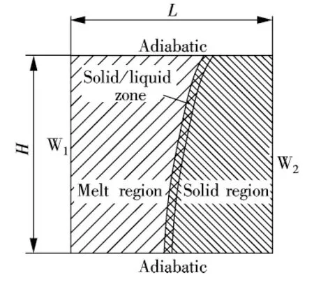
Fig.1 Schematic illustration of the physical model
1.2 Mathematical Model
1.2.1 Assumptions
The following simplifying assumptions are made to obtain the volume averaged conservation equations:
1) The flow and heat transfer are two-dimensional and laminar.
2) The porous media and fluid are incompressible and the Boussinesq approximation can be invoked.
3) The porous media and the sodium (solid or liquid) are at a local thermal equilibrium.
1.2.2 Governing equation
Porous media is modeled by adding a momentum source term to the standard fluid flow equations. The source term is composed of two parts: a viscous loss term and an inertial loss term:
(1)

According to the above assumptions, the volume averaged conservation equations are

(2)

(3)
(4)

(5)
whereUis the velocity vector;pis the pressure;βis the coefficient of thermal expansion; andTmeltis the melting temperature of the sodium;εis the fraction fluid in the volume element (that is, porosity),ε=Vf/V;γis the fraction liquid in fluid,γ(t)=Vl(t)/Vf;δis the fraction liquid in the volume element,δ(t)=Vl(t)/V=εγ(t).
2 Results and Discussion
2.1 Model validation

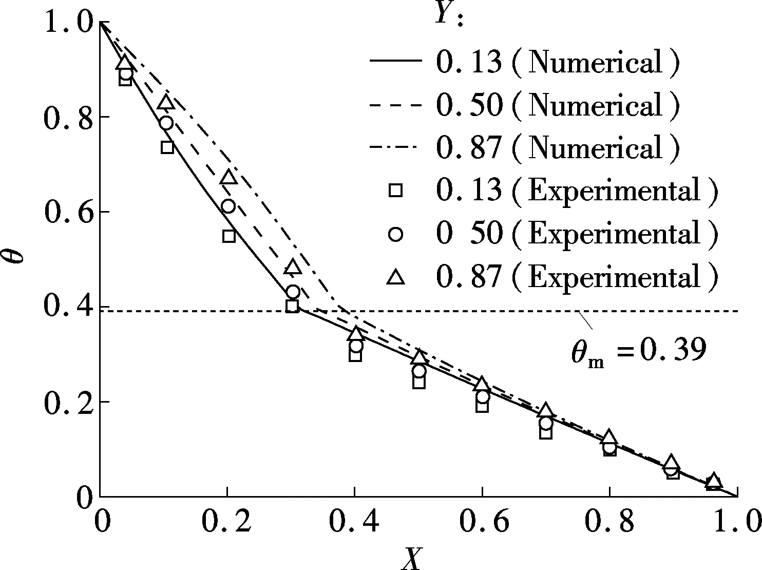
Figs.2 and 3 show the comparisons of the evolution of the melting front and temperature profiles between the present model and the experimental results in Ref.[7]. From Fig.2 (t=1 to 5 min) and Fig.3(a), the deviation between the numerical simulation results and experimental ones in the early melting process is due to the uneven packing of the glass beads at the top of the computational domain. The loose packing causes the local volume fraction of gallium to be larger near the top than in the lower layers, which requires a larger amount of heat to melt them and can explain the slower advance of the melting front. Later in the process (t=20 min), the melting rate of gallium is greatly reduced due to the lower temperature gradients. As the melting rate decreases, the heat transfer is dominated by conduction and convection, and the effect of the uneven packing of glass beads (volume fraction of gallium) on the temperature profile and melting front is greatly diminished. Under these conditions, a good agreement is observed between the measured and predicted melting front locations and temperature profiles, as shown in Fig.2 (t=20 min) and Fig.3(b).

Fig.2 Comparison of the evolution of the melting front
From the above analysis, the current model is valid and can be applied to study a sodium melting process in the porous media of the combined wick.
2.2 Relationship between the structure and the mot-ion speed of the melting front
Fig.4 illustrates the evolution of the melting front in the combined wick with differentδ. In the initial stage of melting, the melting front of sodium moves from the left wall to the right wall gradually. It can be seen that a thinnerδresults in a higher melting rate in the combined wick. The reason is, on the one hand, that the flow resistance becomes less in the combined wick when a thinnerδresults in a larger permeability. On the other hand, the porosity of the combined wick is less whenδis thinner. Less porosity means less solid sodium embedded in the combined wick; thus the absorbed heat is less under the melting process of sodium. The motion speed of the melting front is faster.
(a)

(b)

Fig.4 Comparison of the evolution of the melting front in the combined wick with different δ
Due to the above reasons, the sodium will have a higher melting rate in the combined wick with a thinnerδ, and the heat transfer rate is also higher and then the time for the high-temperature heat pipe startup becomes shorter. It is very important when requiring a fast startup.
2.3 Distribution of temperature and velocity
In the process of the sodium melting, the temperature profiles and the distribution of fluid flow in the combined wick withδof 2, 3 or 4 mm are similar, and thus we only discuss the phase change process in the combined wick withδof 2 mm in this paper.
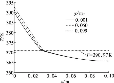
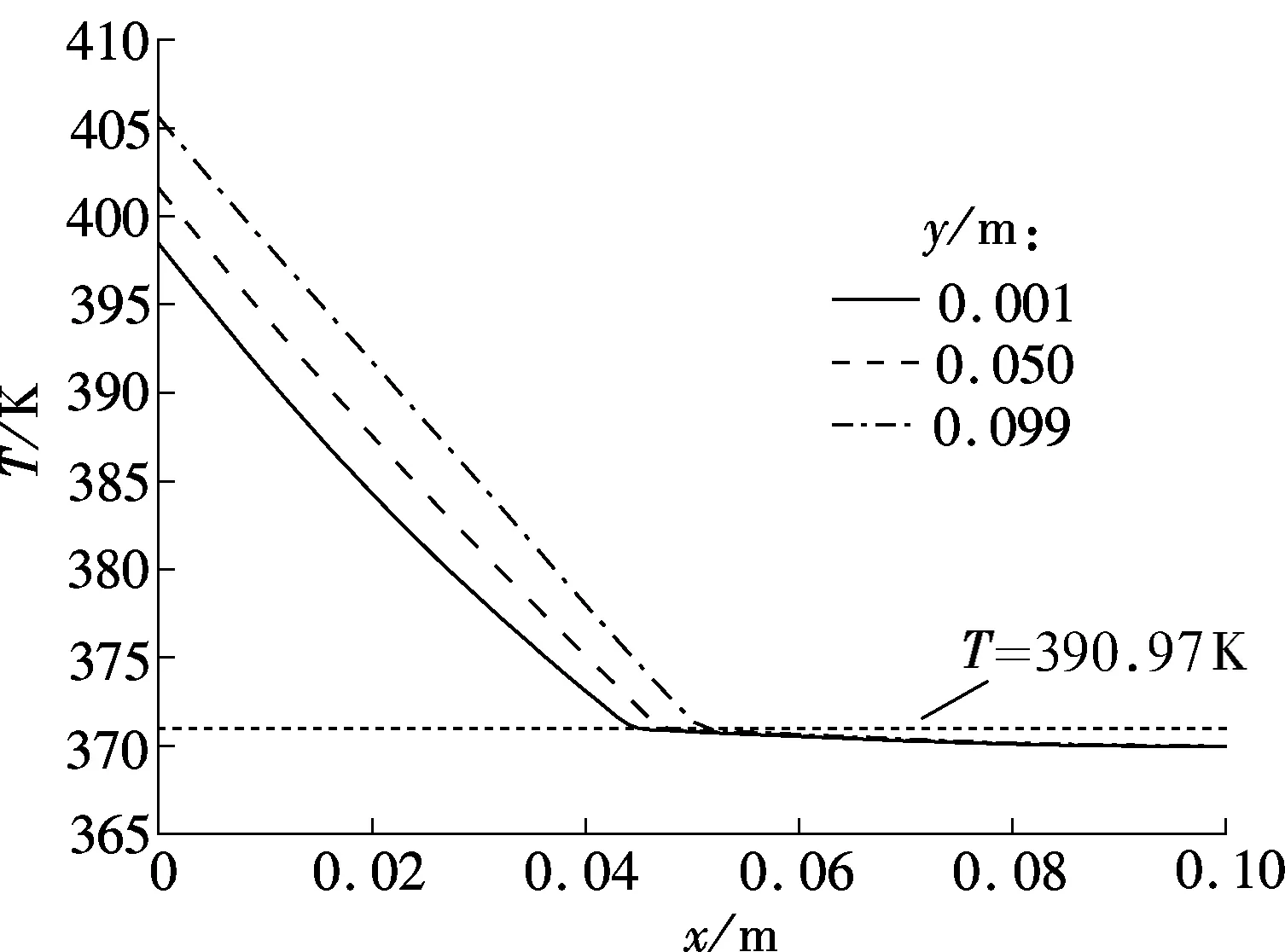
Fig.5 shows the temperature profiles of three different vertical sections in the combined wick withδof 2 mm of 180 and 220 s, respectively. The melting point of sodium is about 370.97 K. The corresponding predicted streamlines are shown in Fig.6.
(a)
(b)
From Figs.5(a) and (b), it can be seen that the temperature difference between the top of the model (y=0.099 m) and the bottom of the model (y=0.001 m) becomes larger and larger with the melting process. The reason is that the sodium close to the heating wall melts first in the initial period; the melting front is almost parallel to the heating wall indicating a conduction dominated melting process; thus the temperature difference at the heating wall is very small, as shown in Fig.6(a). After the initial period, with the amount of molten sodium increasing continuously, buoyancy induced convection heat transfer in the melting becomes increasingly significant, and the melting front gradually becomes the typical shape of convection dominated melting, as shown in Fig.6(b). The melting front moves faster near the top where the liquid, heated by the hot wall, flows in constantly. However, the melting rate decreases toward the bottom, because the liquid cools as it descends along the interface.

(a)
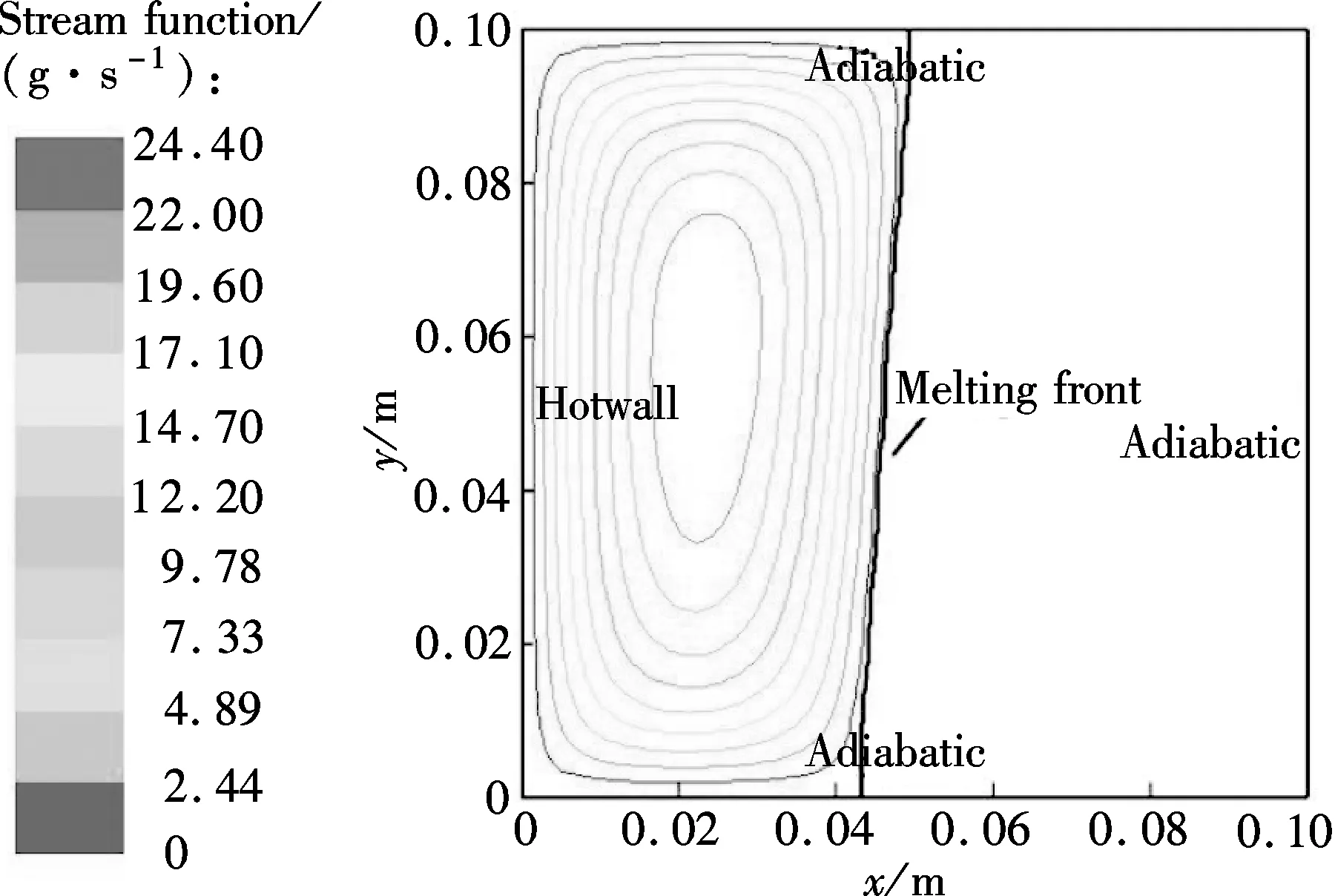
(b) Fig.6 Velocity fields in the combined wick with δof 2mm.(a) t=180 s;(b) t=220 s
2.4 Effect of the wick structure on the temperaturedistribution
Fig.7 shows the temperature distribution of the heating wall with differenty-coordinates in the combined wick with differentδin the sodium melting period. It can be seen that with the melting process, the heating wall temperature difference becomes larger and larger. In the initial period, the temperature distribution on the heating wall is uniform, thus the temperatures at differenty-coordinates are almost the same, as shown in Fig.7 (t=0 to 180 s). With the amount of molten sodium increasing, the convection induced by the density difference becomes more and more significant. The hot upward flow of liquid sodium results in a higher melting rate in the upper region, so the non-uniform temperature distribution on the heating wall appears. As shown in Fig.7, the temperature differences betweeny=0.001m andy=0.099 m in the heating wall of the combined wick are about 14.10, 8.83 and 6.07 K corresponding toδof 2,3 and 4 mm, respectively, fort=280 s. It is observed that a thickerδin the combined wick can lead to a more uniform temperature distribution in the vertical heating wall, and a smaller temperature difference. In most cases, when the temperature distribution in the heating wall is uneven, the overheat spot will likely appear and the process of the high-temperature heat pipe startup may fail. Therefore, a thickerδis beneficial.

Fig.7 The variation of the temperature distribution in the heating wall W1
2.5 Relationship between structure of the combinedwick and melting rate
Fig.8 shows the variation of the maximum velocity of molten sodium in the process of sodium melting in the combined wick with differentδ. It can be seen that in the process of sodium melting there are three obvious stages for the maximum velocity variation, namely, appearance, increasing and decreasing. The maximum velocity of molten sodium increases first, reaches the peak value and then decreases. The peak values in the combined wick withδof 2, 3 and 4 mm are about 0.00255, 0.00168 and 0.00126 m/s, respectively, and the corresponding times are 320, 340 and 350 s, respectively. The reason is, first, that a thickerδin the combined wick will result in a higher flow resistance, and thus the maximum velocity in the melting process of sodium is smaller. Secondly, the porosity of the combined wick is larger whenδis thicker,and the amount of solid sodium embedded in the combined wick is larger, and thus the amount of absorbed heat is larger under the melting process of sodium.
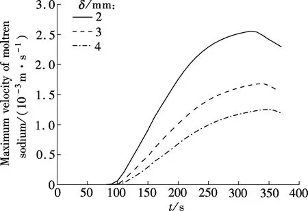
Fig.8 Variation of the maximum velocity of molten sodium in the process of sodium melting in the combined wick with different δ
From the above, the heat transfer capability of the combined wick will weaken with thickening the metal fiber felt, and the maximum velocity of molten sodium will take more time to reach its peak value.
3 Conclusions
1) With a thinnerδ, the melting rate is higher, and it will take less time for the molten sodium to reach the maximum velocity.
2) Due to the natural convection, the hot upward flow of the liquid sodium results in a higher melting rate and temperature in the upper region of the combined wick than those of the bottom.
3) The temperature distribution in the vertical heating wall W1is more uniform in the thicker metal fiber felt of the combined wick.
In conclusion, if the melting rate of sodium in the combined wick with a thinnerδis high, then the time of the high-temperature heat pipe startup can be shortened. However, a thinnerδwill result in a more nonuniform temperature distribution of the heating wall, which increases the possibility of an overheat spot and influences the property of the high-temperature heat pipe. As a result, in the design process of high-temperature heat pipes, the above factors need to be considered fully.
[1]Zhuang Jun, Zhang Hong.Heatpipetechnologyandengineeringapplication[M]. Beijing: Chemical Industry Press, 2000: 66-67. (in Chinese)
[2]Jones B J, Sun D, Krishnan S, et al. Experimental and numerical study of melting in a cylinder[J].InternationalJournalofHeatandMassTransfer, 2006, 49(15/16): 2724-2738.
[3]Zhang Yanchen, Gao Dongyan, Chen Zhenqian. Influence of porosity on melting of phase change materials in metal foams with lattice Boltzmann method[J].JournalofSoutheastUniversity:NaturalScienceEdition, 2013, 43(1): 94-98. (in Chinese)
[4]Jany P, Bejan A. Scaling theory of melting with natural convection in an enclosure[J].InternationalJournalofHeatandMassTransfer, 1988, 31(6): 1221-1235.
[5]Sun D, Garimella S V, Singh S, et al. Numerical and experimental investigation of the melt casting of explosives[J].Propellants,Explosives,Pyrotechnics, 2005, 30(5): 369-380.
[6]Krishnan S, Murthy J Y, Garimella S V. A two-temperature model for solid-liquid phase change in metal foams[J].JournalofHeatTransfer, 2005, 127(9): 995-1004.
[7]Beckermann C, Viskanta R. Natural convection solid/liquid phase change in porous media[J].InternationalJournalofHeatandMassTransfer, 1988, 31(1): 35-46.
[8]Yang Z, Garimella S V. Melting of phase change materials with volume change in metal foams[J].JournalofHeatTransfer, 2010, 132(6): 062301-1-062301-11.
[9]Li Wenqiang, Qu Zhiguo, Tao Wenquan. Numerical study of solid-liquid phase change in metallic foam[J].JournalofEngineeringThermophysics, 2013, 34(1): 141-144. (in Chinese)
[10]Bai Tong, Zhang Hong, Xu Hui, et al. Performance study on a novel combined wick of heat pipe[J].ProceedingsoftheCSEE, 2011, 31(23): 79-85. (in Chinese)
[11]Bai Tong, Zhang Hong, Xu Hui, et al. Investigations of flow resistance through combined heat pipe wick[J].JournalofNanjingUniversityoftechnology:NaturalScienceEdition, 2012, 34(1): 56-60. (in Chinese)
[12]Gray W G, O’neill K. On the general equations for flow in porous media and their reduction to Darcy’s law[J].WaterResourcesResearch, 1976, 12(2): 148-154.
[13]Vafai K, Tien C L. Boundary and inertia effects on flow and heat transfer in porous media[J].InternationalJournalofHeatandMassTransfer, 1981, 24(2): 195-203.
[14]Liu J F, Wu W T, Chiu W C, et al. Measurement and correlation of friction characteristic of flow through foam matrixes[J].ExperimentalThermalandFluidScience, 2006, 30(4): 329-336.
[15]Wu W T, Liu J F, Li W J, et al. Measurement and correlation of hydraulic resistance of flow through woven metal screens[J].InternationalJournalofHeatandMassTransfer, 2005, 48(14): 3008-3017.
[16]Beavers G S, Sparrow E M, Rodenz D E. Influence of bed size on the flow characteristics and porosity of randomly packed beds of spheres[J].JournalofAppliedMechanics, 1973, 40(3): 655-660.
组合式吸液芯内金属钠固-液相变的数值模拟
于 萍1张 红1,2许 辉1沈 妍1
(1南京工业大学能源学院, 南京 211816)(2常州工学院, 常州 213002)
采用有限容积法和焓-多孔介质模型数值模拟了组合式吸液芯内金属钠熔化的固-液相变过程.由于液态金属钠和组合式吸液芯的导热系数在同一数量级,因而采用单温度模型,模拟过程中考虑了非达西效应影响和液态金属钠的自然对流现象.研究结果发现,组合式吸液芯中金属纤维毡厚度越小,金属钠受热熔化的速度越快,且熔化后的液态钠流速达到最大值所用的时间越短,进而可以缩短热管启动时间;组合式吸液芯中金属纤维毡厚度越大,竖直加热壁面的温度分布越均匀、壁面温差越小,进而减少了加热壁面产生过热点的可能.
固-液相变;组合式吸液芯;金属钠;多孔介质
TK172.4
Received 2014-05-06.
Biographies:Yu Ping (1985—), female, graduate; Zhang Hong (corresponding author), female, doctor, professor, hzhang@njut.edu.cn.
s:The National Natural Science Foundation of China (No.51076062), the Scientific Innovation Research of College Graduates in Jiangsu Province(No.CXZZ12_0421).
:Yu Ping, Zhang Hong, Xu Hui, et al.Numerical simulation for solid-liquid phase change of metal sodium in combined wick[J].Journal of Southeast University (English Edition),2014,30(4):456-461.
10.3969/j.issn.1003-7985.2014.04.010
10.3969/j.issn.1003-7985.2014.04.010
猜你喜欢
杂志排行

Journal of Southeast University(English Edition)的其它文章
- Simulation of urban affordable housing land-use evolution based on CA-MAS model
- Dynamical chiral symmetry breaking in QED3
- A decision model of optimal production reliability and warranty length in an imperfect production system
- Metal cation crosslinking of TiO2-alginate hybrid gels
- One-pot facile synthesis of highly photoluminescent graphene quantum dots with oxygen-rich groups
- Modeling household car ownership using ordered logistic regression model