One-piece coal mine mobile refuge chamber with safety structure and less sealing risk based on FEA
2014-08-08ZHAOHuanjuan赵焕娟QIANXinming钱新明HUANGPing黄平WANGChen王晨
ZHAO Huan-juan(赵焕娟), QIAN Xin-ming(钱新明), HUANG Ping(黄平),WANG Chen(王晨)
(State Key Laboratory of Explosion Science and Technology, Beijing Institute of Technology, Beijing 100081, China)
One-piece coal mine mobile refuge chamber with safety structure and less sealing risk based on FEA
ZHAO Huan-juan(赵焕娟), QIAN Xin-ming(钱新明), HUANG Ping(黄平),WANG Chen(王晨)
(State Key Laboratory of Explosion Science and Technology, Beijing Institute of Technology, Beijing 100081, China)
In order to reduce the risk of sealing and improve the structural strength for a coal mine mobile refuge chamber, a new type of one-piece model was designed. Mechanical and mathematical calculation performed an important role. Calculated according to statics and relevant contents, the structure had the same total volume as the traditional segmented structure, but had shorter length, wider width and greater height. Those prevented the structure from stress or deformation failure. Some reinforcing ribs with enough moments of inertia were welded in the external shell. Because of the one-piece structure, this refuge chamber reduced the risk of sealing which was a serious problem of segmented structure. Impact load with 300 ms duration and 0.6 MPa over-pressure was settled. Explicit nonlinear dynamic analysis program was used to simulate the response of the refuge chamber. The maximum stress and the maximum displacement were obtained. The refuge chamber including blast airtight doors could meet the rigidity requirement. Weak parts of the chamber were the front and back end shell where bigger displacement values occurred than others. Thus, the calculation indicated that the refuge chamber could meet structural safety requirements. Based on the numerical analysis, suggestions were put forward for further resistance ability improvement. Only large inclined shaft with larger wellhead was suitable for this one-piece coal mine mobile refuge chamber.
coal mine safety; structure optimization; refuge chamber shell; finite element analysis(FEA); impact load
As one fifth of mine disasters, mine gas explosion brought heavy casualties and great loss each year in China. Miners were not able to evacuate after accidents due to many kinds of risks, such as oxygen depletion near explosion area, high-temperature smoke or high concentrations poisonous gases and so on[1]. State Administration of Work Safety[2]indicated that the percentage of miners killed due to those reasons was about 80%. Besides, about 75% mine gas explosion death was caused by the toxic and harmful gas. Because the concentration of carbon monoxide can reach 1%-4%, the highest can even be 7%-8%, it may be the most harmful kind of gas in the explosion. During accidents, there are great impact loads and stresses put on the refuge chamber. Therefore, the refuge chamber should have enough impact resistance strength.
In earlier research, key technology[3-4], a risk-based design methodology[5], heat-shielding performance[6]and the views about the physical discomforts and psychological stresses[7]for refuge chamber capsule had been mature. Ming Song et al.[8]investigated buckling capacity optimization of coal mine refuge chamber’s shell under a uniform axial compression. L.D. Ma et al.[9]also proved that there was an obvious relationship between the ability of refuge chamber under axial impact load and the thickness of flat spherical shells. For further study, Huanjuan Zhao et al.[10]used FEA to indicate the segmented type chamber would not be damaged even when explosion suddenly happened.
This segmented structure is similar to a large thin-walled sealing capsule[11]. Jiao Jian et al.[12]had solved the sealing problem of doors. Therefore, a new kind of specific structure form should be designed according to the applicable condition of one-piece type. Further improved simulation calculation for this chamber form under explosion load should be done. Finite element analysis would be used to analyze the stress and deformation. The maximum stress and plastic deformation would be found out to determine whether the structure was damaged. And weak parts would also be located. Based on analysis, further improvements could be put out.
1 Design methods
Thickness and reinforcing ribs need to be designed and checked. Structure should be carefully designed to meet the safety requirement with lighter weight. Each side could be simplified as a simply supported beam under distributed loads. This problem could be solved in two ways. One way is to cut short the length while effective volume was assured, whereupon deflection in middle would be decreased. The other way is to weld reinforcing ribs on the shell surface to reinforce flexural rigidity. A reasonable structure is built with mine ventilation and mine size should be taken into consideration.
1.1 Design of the size
Considering installation requirements, transition or equipment compartment should be reserved in the front and rear. The gas coal-dust explosion pressure may be higher than 0.9 MPa, and temperature may be beyond 2 000 ℃[13]. So, the shell should meet mobile medium voltage steel container’s structure strength requirements to avoid potential safety problems. According to the requirements[14], Q345R[15]steel was chosen.
① Avoiding stress failure
Bending moment diagram of the side simply supported beam was shown in Fig.1a. Side maximum stress was calculated as

(1)
End face has a rectangular section. Bending moment diagram of the end face simply supported beam was shown in Fig.1b. End face maximum stress was calculated as
(2)
where0≤h≤2 500 mm,0≤b≤2 500 mm, 0≤δe≤20 mm.
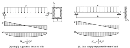
Fig.1 Bending moment diagram of simply supported beams
② Avoiding deformation failure
The maximum deflection should be in the range of 0 to 2% to avoid deformation failure. Side maximum deflection was calculated, and end face maximum deflection as follows:
(3)

(4)
③ Satisfying requirement of volume
The whole volume should be around two or three times of the effective volume. 22 m3would be an appropriate value of the whole volume, expressed by following equation
V=lbh=22 m3.
(5)
σc,σcf,fandffwere calculated to be in the same order of magnitude and the 2-norm of them was chosen as the weight function ofl,b,handδe. A program was made by using exhaustive search method (ESM) to find the minimum values ofσc,σcf,fandff. The numerical results show that whenl,b,hare 5 575 mm, 2 050 mm, 1 925 mm,σc,σcf,fandffgain the minimum values.
1.2 Design of thickness
Shock wave was a typical non-periodic load in short duration. Equivalent static load could be found for triangular wave as follows[16].
(6)
wherePeis a static load, Pa,Pmaxis the peak pressure of dynamic load force on shell, Pa,Cdis the equivalent coefficient of dynamic load,t1is the duration of triangular wave[17], ms.
Converting the cuboid kind into thecylindrical kind could make it satisfy with above equations. There were three conversion methods. All were for the cross-section. It was converted into cylinder with the same volume. Considering the structural stability, cross-section of inscribed circle should be presented. To gain enough volume, cross-section of circumscribed should be figured out.

(7)
2R2=h=1 925(mm),
(8)

(9)
whereR1,R2,R3are the corresponding radius.
The same distributed load was loaded on the cylinders and the cuboid. The maximum stress of cylinders was calculated as follows
(10)
whereIznis the moment of inertia expression of circular cross-sections,D0nis the external diameter of each circular cross-section.
A program forσnandσcwas written using MATLAB. The image results show relative sizes ofσnandσcin the same value ofδe. Therefore, the analysis shows cylinder with the same volume has good mechanical properties. ChoosingR1as calculation radius was sensible.
σl(δe)≥σ2(δe)≥σ1(δe)≥σ3(δe),
0 mm≤δe≤20 mm.
(11)
Stress-strain coefficients could be investigated by correlation coefficients[15]. The allowable stress was calculated as

(13)
Thickness calculation formulas were evidently given as
170(MPa)>Pe.
(12)
Considering corrosion allowance and allowable deviation of thickness[18], specific plate thickness was determined as
δ=6.930 4+2+0.55=9.480 4(mm).
(14)
Analysis shows that 10 mm steel plate was sensible for the shell.
1.3 Design of reinforcing rib
The reinforcing ribs welded in internal might have better flexural effect, but it occupied capsule space which was supposed to install heat preservation facilities. To weld reinforcing ribs with the shape of “#” in the surface is feasible to decrease damage. The structure was shown in Fig.2. There are two airtight doors set inside the refuge chamber except protective airtight doors. Space between two airtight doors has a life supporting compartment. Airtight doors have internal support effect to improve the strength and stiffness of refuge chamber whilst providing convenience for internal arrangement.
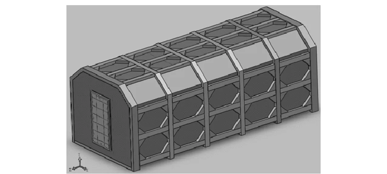
Fig.2 Geometry constructional of refuge chamber
2 Numerical computation and results
2.1 Numerical modelling
As the structure was mainly connected by welding and bolted connections, there were no relative motion parts, so hypothesis was assumed: the welding of structural parts was completely reliable. There was no penetration between structural parts. All stress of welding was eliminated. There was no deformation about manufacture or installation. Bolted connection was reliable. There was no effect produced by pre-stressed of bolted connection.
The same blast load was loaded on five sides. Peak pressure was 0.6 MPa. Pulse width was 300 ms, as shown in Fig.3. SHELL163 element was for shell and reinforcing rib, and SOLID164 element for cabin doors. The spring-damper element was used to partition threaded connection. The biggest shell element size was set to 50. There were 273 316 elements totally, as shown in Fig.4.
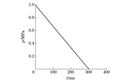
Fig.3 Pressure-time curve of shock wave
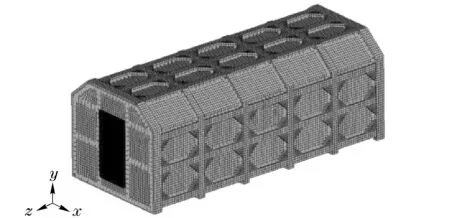
Fig.4 Model of finite element mesh
2.2 Results and discussion
2.2.1 Stress results
The remarkable stress results were shown in Fig.5. The light is high location. The maximum stress (371.3 MPa) appeared at the middle and chamfering position of side reinforcing rib. Stress of few elements exceeded the material yield strength, but did not exceed tensile strength. Connection stress value between protective airtight door and door frame is less than material yield strength. The established refuge chamber could meet the required strength. It was difficult for theoretical calculation to embody stress concentration. But cloud charts could show stress concentration clearly.
Stress-time curve of one element withhigh stress was shown in Fig.6. Stress extremely reached great value in the beginning. This characteristic was due to the shock wave mutations. Main external forces were shock pressure and tensile force from shell bending. Shock pressure was very big, whereas tensile force was very small as shell bending was minute. So, the velocity of stress was big. Then, general trends of stress were smaller and smaller with the inevitable fluctuation. Finally, it tended to zero. Analysis showed there was no plastic strain in this element. Stress results are consistent with influence of shock wave.
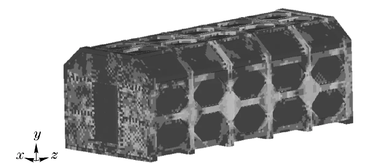
Fig.5 Remarkable stress cloud
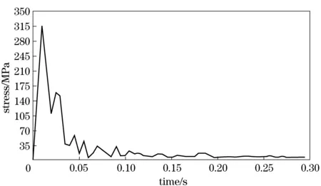
Fig.6 Stress-time curve with maximum stress
2.2.2 Displacement results
The remarkable displacement results were shown in Fig.7. The maximum (11.82 mm) displacement appeared at the middle position of end face. Reinforcing rib strengthened shell. The maximum displacement of main blast airtight door and escape blast airtight door were 7.050 mm and 6.538 mm, and appeared at edge positions and connection places of door planks. Because door displacement and relative displacement is very small, seal will not be affected. Obviously, reinforcing rib had strengthened the shell and protected it. Meanwhile, internal airtight door took as a support role, too. Displacement-time curve with high displacement was shown in Fig.8.
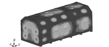
Fig.7 Remarkable displacement cloud

Fig.8 δ-t curve with maximum displacement
2.2.3 Results analysis
The place where the maximum occurred could be clearly found out. Stress concentration would be abated. Larger inner diameter round corner should be used to improve chamfering angles. The front and back end shells had bigger displacement values. Flexural rigidity must be increased to enhance impact resistance. There were two methods for optimizing. One was using arc structures in the front and back end shells. It could buffer outside pressure and would not bring too much weight. However, this method requires high technology. The other was to thicken the end shell or weld reinforcing rib on the end shell. Rectangular tube and flat steel would be chosen for the mechanical characteristics. Rectangular tube could be welded in the external shell while flat steel in the internal shell.
3 Conclusions
Firstly, having shorter length and wider width was the way of fabrication for the one-piece coal mine mobile refuge chamber. One model with certain size was set up to solve design difficulties for the refuge chamber. Overall length was 5.40 m while width was 2.25 m. It met with volume requirements. The refuge chamber had reinforcing ribs welded in external shell. Rectangular tube acted as a reinforcing rib. This one-piece type did not involve sealing problems between segments. It could contribute to reducing risk of sealing.
Secondly, a simulation analysis was used to confirm its structure safety. Verified finite element analysis was used to simulate the response under a blast loading. The maximum pressure of the triangle impact load was 0.6 MPa, and the pulse width was 300 ms. And there was no large plastic deformation. Only minimum plastic deformation existed at a rare unit. The refuge chamber including blast airtight doors could meet rigidity requirements. Weak parts of this refuge chamber focused on places where the displacement value was bigger such as the front and back end shells. The results ensured that the fabrication way can meet the requirements of certain resistance impact. The simulation analysis results proved that the size was appropriate. Considering safety coefficient, it would be much safer when the maximum pressure of the triangle impact load was 0.5 MPa.
Finally, based on the numerical analysis, suggestions were put forward for further resistance ability improvement. Stress concentration would be abated. Arc structure might be used in the front and back end shells. The front and back end shells might be thickened. Then, this refuge chamber could be strengthened.
This one-piece model had solved strength security problems and cut down sealing between segments. But dimensional requirement was higher when it descended in the well. Only an inclined shaft with a larger wellhead was suitable for this one-piece coal mine mobile refuge chamber.
[1] Zhou X, Chen G. The probability analysis of occurrence causes of extraordinarily serious gas explosion accidences and its revelation[J]. Journal of China Coal Society, 2008,33: 42-46. (in Chinese)
[2] State Administration of Work Safety, 2004—2009. Coal mine accident analysis report of China[R]. Beijing: The State Administration of Work Safety, 2010. (in Chinese)
[3] Fasouletos M A. Parametric design of a coal mine refuge chamber[M].[S.l.]: ProQuest, 2007.
[4] Jiping S. The key technologies of the refuge chamber and rescue capsule in the underground mine[J]. Journal of China Coal Society, 2011,36: 713-717. (in Chinese)
[5] Huang X. A risk-based design methodology for coal mine refuge chamber[C]∥IEEE, 2011:199-202.
[6] Fang H F, Ge S R, Song M. Analysis on effect of heat bridge to heat transfer of refuge chamber's shell[J]. Advanced Materials Research, 2011,211: 624-628.
[7] Margolis K A, Westerman C Y K, Kowalski-Trakofler K M. Underground mine refuge chamber expectations training: program development and evaluation[J]. Safety Science, 2011,49(3): 522-530.
[8] Song M, Ge S R, Fang H F. Analysis of dynamic response of mine rescue chamber under axial impact load[J]. Advanced Materials Research, 2011,211:576-580.
[9] Ma L D, Pan H Y, Wang Y, et al. Lightweight structure design of refuge chamber[J].Advanced Materials Research, 2012,472: 823-826.
[10] Zhao H, Qian X, Li J. Simulation analysis on structure safety of coal mine mobile refuge chamber under explosion load[J]. Safety Science, 2011,50(4): 674-678.
[11] Zhao C, Wang Z. Large-scale thin-walled welding sealing capsule technology research[J]. Spacecraft Engineering, 2004,13(3):32-36.
[12] Jiao J, Zhu H. Locking mechanism design of mine rescue cabin door[J]. Coal Mine Machinery, 2011, 32(3): 42-44. (in Chinese)
[13] Cai Zhouquan, Luo Zhenmin. Experimental study on propagation characteristics of gas/coal dust explosion[J]. Journal of China Coal Society, 2009, 34(7): 938-941. (in Chinese)
[14] The Boiler Pressure Vessel Standardization Technical Committee. GB 150—2011. Pressure vessels[S]. Beijing: China National Standardization Committee, 2011- 11- 21.
[15] The National Steel Standardization Technical Committee. GB713—2008. Steel plates for boilers and pressure vessels[S].Beijing:China National Standardization Committee, 2008- 09- 01. (in Chinese)
[16] Zhao Shida. Blast chamber[J]. Explosion and Shock Waves, 1989, 9(1):85-96. (in Chinese)
[17] Yuan Xi, Li Shunming. Natural vibration analysis of thin rectangular plate under different boundary conditions[J]. Aeroengine,2005, 31(3):39-43. (in Chinese)
[18] The National Steel Standardization Technical Committee. GB/T 709—2006. Dimension,shape, eight and tolerances for hot-rolled steel plates and sheets[S]. Beijing: China National Standardization Committee, 2006- 11- 01. (in Chinese)
(Edited by Wang Yuxia)
2013- 01- 30
Supported by the Major State Basic Research Development Program of China (973 Project)(2011CB706900)
TD 774 Document code: A Article ID: 1004- 0579(2014)02- 0152- 06
E-mail: qsemon@bit.edu.cn
猜你喜欢
杂志排行
Journal of Beijing Institute of Technology的其它文章
- Expert ranking method based on ListNet with multiple features
- Investigating fatigue behavior of gear components with the acoustic emission technique
- Contour tracking using weighted structure tensor based variational level set
- Consensus problem of multi-agent systems under arbitrary topology
- Three-dimension micro magnetic detector based on GMI effect
- On measured-error pretreatment of bionic polarization navigation
