Experimental Research on Flash Boiling Spray of Dimethyl Ether
2014-07-30PengZhang
Peng Zhang
China Ship Development and Design Center, Wuhan 430064, China
1 Introduction1
The flash boiling spray has the potential to improve engine performance since it can be used to promote the atomization of fuels with a large spray cone angle and a smaller droplet Sauter mean diameter (SMD) (Zenget al.,2012; Duanet al., 1999; Lienhard and Stephenson, 1996;Eranet al., 2008; Yuet al., 2007). In recent years, the research on flash boiling spray was mainly focused on superheated liquefied fuel and fuel containing dissolved gas(Kawanoet al., 2004; Zeng and Lee, 2002; Zuoet al., 2000;Ra and Reitz, 2004; Houet al., 2005; Maet al., 2007).However, little has been reported about the characteristic research on flash boiling spray of fuels with low boiling point and high saturated vapor pressure, which has attracted widespread attention at present. As a clean fuel with potential long-lasting resources, dimethyl ether (DME) has been considered as a promising alternative fuel for compression-ignition engine (ICE) in recent years (Wanget al., 2004; Lüet al., 2003). The low boiling point and high saturated vapor pressure nature make the DME spray undergo flash boiling at lower ambient pressure (Wakaiet al., 1999; Yuet al., 2002), while the atomization of fuel plays a very important part in determining the temporal and spatial distribution of fuel in ICE which influences subsequently the quality of combustion and finally the performance and emissions of ICE (Wang and Zhou, 2001;Wenet al., 2003; Zhouet al., 2007). Therefore, the experimental research on DME spray under flash boiling condition is of great significance.
This paper consists of the experimental results of flash boiling spray characteristics, including the spray shape, the spray tip penetration and the spray angle, for liquid DME injected by a single-hole nozzle under different nozzle opening pressures and nozzle hole diameters. This study is the preliminary research for further understanding of air-fuel mixing and consequent combustion by adding the DME into ICE. Also, this study is helpful in offering a comprehensive database for the flash boiling spray characteristics of DME.
2 Experimental apparatus and conditions
Fig. 1 shows the schematic diagram of the experimental setup, it consists of a constant volume chamber, a single-hole injector, a fuel supplying system, a light source and optical system, an electronic controlling circuit and a high-speed digital imaging system. Two sides of the chamber are transparent to make the process of spray observable. In the light source and optical system, a common bulb rated for 2 kW is adopted to illuminate the constant volume chamber, and a frosted glass is placed between the bulb and chamber to reduce inhomogeneous impact of light intensity on imaging effect. In order to avoid evaporation of the DME in fuel supplying system, the DME tank is directly pressurized up to 1.8 MPa by nitrogen. In addition, some lubricating oil is added into the DME to prevent wear of fuel supplying system. The Fastcam_SA1.1,which is produced by Photron Limited Corporation of Japan,is adopted in this experiment to capture the spray images using the software called Motion Plus. The frame rate is set at 30 000 fps, which is much higher than that in similar studies. Thus, many details about DME flash boiling spray are captured. About 5 processes of spray under the same experimental condition can be captured by the high-speed digital camera, the second process is chosen as the investigated subject because the fuel pressure is not established fully in the high-pressure fuel pipe during the first spray. The detailed experimental conditions are listed in Table 1.
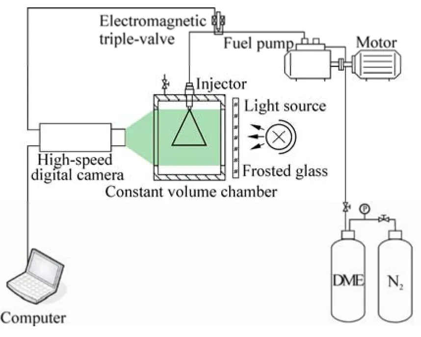
Fig. 1 Schematic diagram of experimental setup
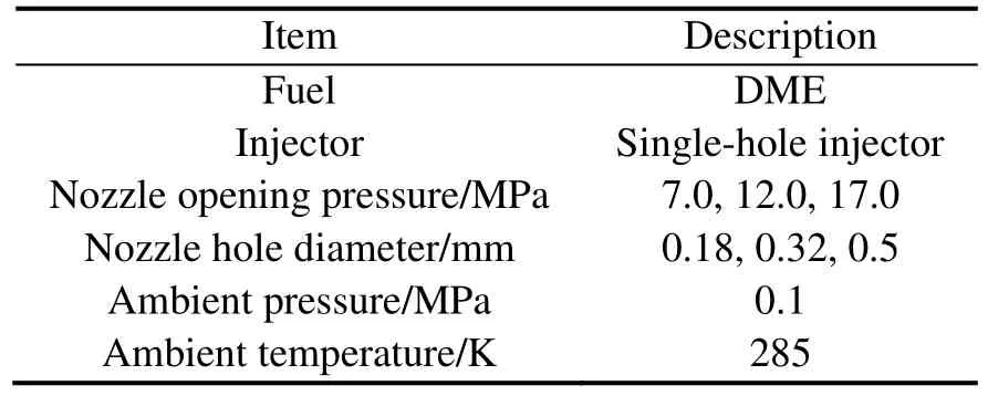
Table 1 Experimental conditions of spray
3 Results and discussion
3.1 Structure of flash boiling spray
Spray shape, spray tip penetration and spray angle are usually used to characterize the macroscopic spray structure.In this study, the spray tip penetration and spray angle were directly measured from the spray image captured by the high-speed digital camera. Considering the spray shape near the nozzle tip takes on parabolic pattern, the spray angles were obtained by measuring the angles between two tangent lines of the edges of spray near the nozzle tip. In addition,the distance from the nozzle tip to the leading end of spray was defined as the spray tip penetration of the whole spray.Fig. 2 gives the definitions of spray tip penetration and spray angle.
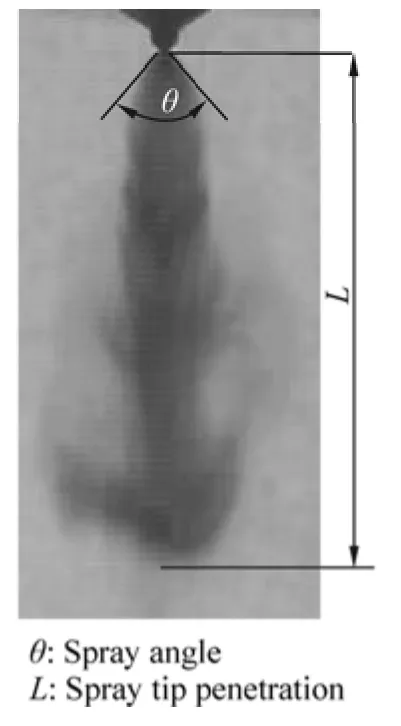
Fig. 2 Definitions of spray tip penetration and spray angle
3.2 Influence of nozzle opening pressure
The spray images for liquid DME under three kinds of nozzle opening pressures are provided in Figs. 3, 4 and 5 respectively. Usually, a higher nozzle opening pressure will result in a higher maximum injection pressure, and thus the influence of nozzle opening pressure on injection process can represent that of maximum injection pressure to a large extent. For the limit of paper length, the time interval between two spray images is taken as 1/15 000 s. The formation and development of vortex ring structure are clearly observed in Fig. 4. When the liquid DME is injected into the constant volume chamber, the bubble begins to form,grow and break up in the spray because of the superheated state, which extends the spray in the radial direction. The greater air drag on the larger spray leading end resulting from the radial extended effect of bubble growth and breakup on the fuel jet (Zeng and Lee, 2001) largely contributes to the formation of vortex ring structure, and the appearance of vortex ring structure is a typical characteristic of the flash boiling spray (Ogumaet al., 2002; Leeet al.,2001; Yu and Bae, 2003; Yuet al., 2009). When the vortex ring structure begins to form on two sides of the spray leading end at about 0.210 9 ms after start of injection, the spray leading end takes on inverted mushroom-like shape at the same time. As the spray develops with time, the two sides of the spray leading end shrink radially and narrow gradually because of the effect of air entrainment produced by vortex ring structure. Meanwhile, the spray shape near the nozzle tip takes on parabolic pattern. As the time goes on,the vortex ring structure begins to become large and long under the action of air drag. In addition, the spray leading end begins to change from inverted mushroom-like shape to anchor-like one and disappears gradually because of the evaporation of droplets. Because the jet velocity of fuel is higher, the time when the vortex ring structure forms under the highest nozzle opening pressure in Fig. 3 is later compared with that in Fig. 4. For the same reason, the radial extended effect of bubble growth and breakup on the fuel jet is not obvious in Fig. 3, while the following development of vortex ring structure is relatively rapider, which can be attributed to the greater air drag on the spray leading end.
Fig. 5 shows the dynamic process of DME flash boiling spray under the lowest nozzle opening pressure. As can be seen in Fig. 5, the vortex ring structure forms earlier and develops slower compared with the phenomena observed in Fig. 4. The reasons can be analyzed similarly.

Fig. 3 Images of DME flash boiling spray development (first image 0.056 4 ms, nozzle opening pressure 17.0 MPa, nozzle hole diameter 0.5 mm)
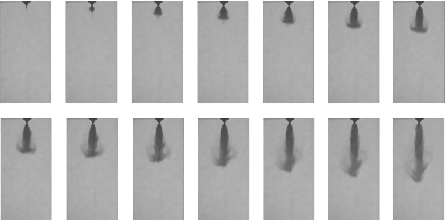
Fig. 4 Images of DME flash boiling spray development (first image 0.044 4 ms, nozzle opening pressure 12.0 MPa, nozzle hole diameter 0.5 mm)
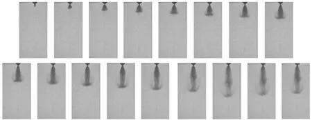
Fig. 5 Images of DME flash boiling spray development (first image 0.05 ms, nozzle opening pressure 7.0 MPa, nozzle holediameter 0.5 mm)
Figs. 6 and 7 show the variations of spray tip penetration and spray angle versus time under three kinds of nozzle opening pressures, respectively. It can be seen that under the influence of pressure fluctuation in the fuel injection system,the spray tip penetration has acceleration during the injection. This phenomenon is similar to the results observed by Suhet al. (2006). Obviously, the spray tip penetration increases with the enhancement of nozzle opening pressure. In addition, the variation curves of spray angle versus time approximately take on the letter U shape.This means the spray angles in the middle stage of injection are smaller than those at the early and late stages of injection. The reason these phenomena occur is that the fuel jet velocity is lower at the early and late stages of injection,and the bubble growth and breakup have a greater radial extended effect on the DME jet. Meanwhile, Fig. 7 illustrates that with the enhancement of nozzle opening pressure, the spray angle decreases.
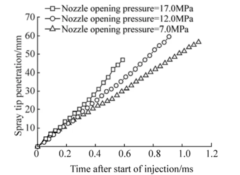
Fig. 6 Variation of spray tip penetration vs. time under different nozzle opening pressures
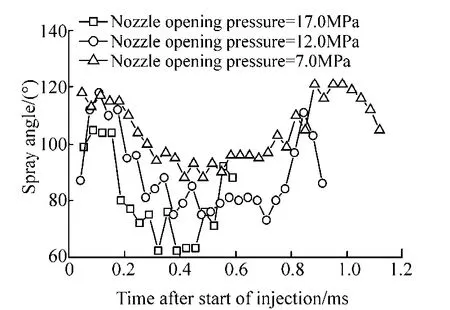
Fig. 7 Variation of spray angle vs. time under differentnozzle opening pressures
3.3 Influence of nozzle hole diameter
Figs. 8 and 9 provide the DME spray images under two nozzle hole diameters, respectively. For the limit of paper length, the time interval between two spray images is also taken as 1/15 000 s. It can be seen from Fig. 8 that the vortex ring structure forms later and its size is smaller compared with that in Fig. 4, because the smaller nozzle hole diameter decreases the front face area of spray as well as the air drag on the spray leading end. Besides, the decrease of bubble number in the fuel jet for smaller nozzle hole diameter weakens the radial extended effect of bubble growth and breakup on the fuel jet. In the following developing process of spray, the evolution of vortex ring structure is not distinct since the air drag on the spray leading end is smaller for smaller front face area of spray. As shown in Fig. 9, because the nozzle hole diameter is too small, the main spray body is very slim and the formation and development of vortex ring structure is hardly observed.
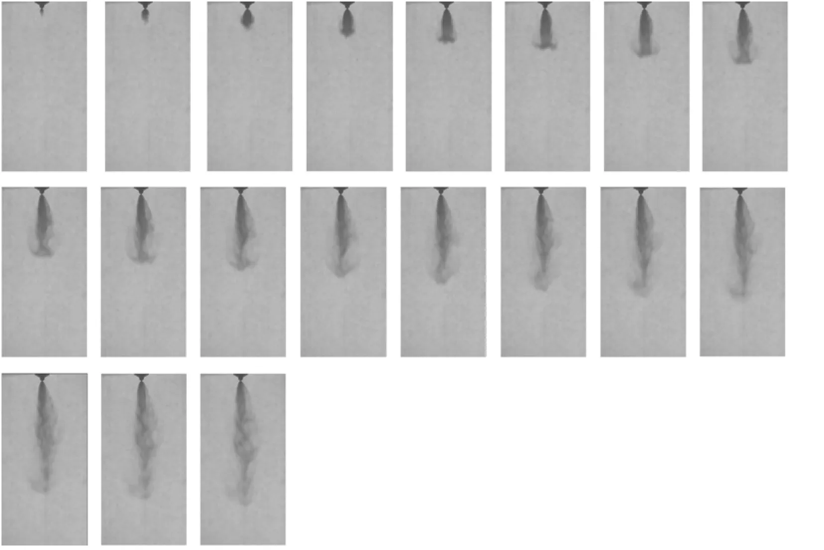
Fig. 8 Images of DME flash boiling spray development (first image 0.066 7 ms, nozzle opening pressure 12.0 MPa, nozzle hole diameter 0.32 mm)
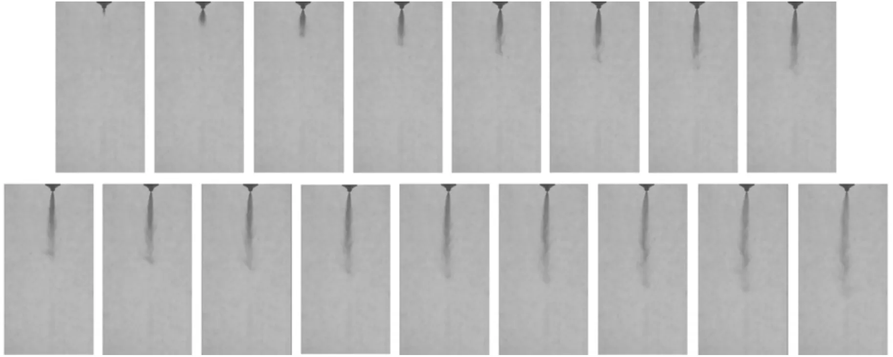
Fig. 9 Images of DME flash boiling spray development (first image 0.063 9 ms, nozzle opening pressure 12.0 MPa, nozzle hole diameter 0.18 mm)
The spray tip penetrations and spray angles for different nozzle hole diameters are shown in Figs. 10 and 11. Clearly,the effect of nozzle hole diameter on the spray tip penetration is relatively complicated, i.e., the spray tip penetration is longer under smaller nozzle hole diameter at the early stage of injection, the situation is opposite at the late stage of injection. On the one hand, the decrease of nozzle hole diameter brings smaller front face area of spray and air drag acting on the spray leading end, which is favorable to increase the spray tip penetration. On the other hand, the smaller droplets injected by nozzle with smaller hole diameter decelerate quickly in the ambient air, which decreases the spray tip penetration. Thus, the complication of variation of spray tip penetrations versus time can be attributed to the competition between the positive factor and passive one mentioned above. Similarly, the variation curves of spray angle versus time also take on the letter U shape, and the smaller the nozzle hole diameter, the smaller the spray angle.
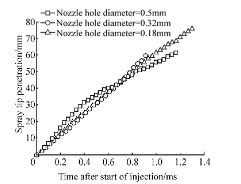
Fig. 10 Variation of spray tip penetration vs. time under different nozzle hole diameters
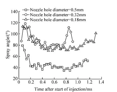
Fig. 11 Variation of spray angle vs. time under different nozzle hole diameters
4 Conclusions
The liquid DME spray undergoes flash boiling at lower ambient pressure for its low boiling point and high saturated vapor pressure nature. The formation and development of vortex ring structure during the injection is a typical characteristic of flash boiling spray. The experimental results indicate that the combined action of the bubble growth and breakup in the spray and the air drag on the spray leading end determines the formation and development of vortex ring structure of flash boiling spray; with the enhancement of nozzle opening pressure, the spray tip penetration increases and the spray angle decreases; while the influence of nozzle hole diameter on the spray tip penetration is relatively complicated, the variation of spray angle is in accordance with that of nozzle hole diameter.
Duan SL, Feng L, Song YC, Chen JH (1999). The investigation on droplet distribution and combustion characteristics of flash boiling spray in diesel engines.Transactions of Chinese Society for Internal Combustion Engines, 17(1), 54-58. (in Chinese)
Eran S, Tali BK, Alexander R (2008). Flash-boiling atomization.Progress in Energy and Combustion Science, 34, 417-439.
Hou YC, Huang Z, Xiao J, Qiao XQ, Lü XC (2005). Phase change in the spray of reformulated n-dodecane fuel with liquefied CO2.Transactions of Chinese Society for Internal Combustion Engines, 23(2), 113-118. (in Chinese)
Kawano D, Goto Y, Odaka M, Senda J (2004).Modeling atomization and vaporization processes of flash-boiling spray.SAE technical paper, Paper 2004-01-0534.
Lee SW, Jin K, Yasuhiro D (2001). Spray characteristics of alternative fuels in constant volume chamber (comparison of the spray characteristics of LPG, DME and n-Dodecane).JSAE Review, 22(3), 271-276.
Lienhard JH, Stephenson JM (1996). Temperature and scale effects upon cavitation and flashing in free and submerged jets.ASME Journal of Basic Engineering, 6, 525-532.
Lü XC, Huang Z, Li XL (2003). A survey of world investigation on DME as alternative fuel.Vehicle Engine, (4), 39-42. (in Chinese)
Ma ZZ, Qi YL, Xu BY (2007). Research on LPG spray for liquid phase injection system.Journal of Shandong Jianzhu University, 22(2), 131-135. (in Chinese)
Oguma M, Hyun G, Goto S, Sugiyama K (2002).Atomization characteristics for various ambient pressure of dimethyl ether(DME). SAE technical paper, Paper 2002-01-1711.
Ra YC, Reitz RD (2004). A model for droplet vaporization for use in gasoline and HCCI engine applications.Journal of Engineering for Gas Turbines and Power, 126(4), 422-428.
Suh HK, Park SW, Lee CS (2006). Atomization characteristics of dimethyl ether fuel as an alternative fuel injected through a common-rail injection system.Energy and Fuels, 20(4),1471-1481.
Wakai K, Yoshizaki T, Nishida K, Takezaki T (1999).Numerical and experimental analyses of the injection characteristics of dimethyl ether with a D.I. diesel injection system. SAE technical paper, Paper 1999-01-1122.
Wang HW, Zhou LB (2001). Study on spray characteristics of dimethyl ether.Journal of Xi’an Jiaotong University, 35(9),918-921. (in Chinese)
Wang Y, Dong HY, Zhou LB, Pan KY (2004). Investigation of the performance of diesel engine fueled with dimethly ether and vehicle driving test.Journal of Xi’an Jiaotong University,38(1), 24-27. (in Chinese)
Wen H, Liu YC, Wei MR, Zhang YS (2003). Analysis of the spray characteristics of DME and diesel by numerical simulation.Transactions of Chinese Society for Internal Combustion Engines, 21, 199-204. (in Chinese)
Yu J, Bae C (2003). Dimethyl ether (DME) spray characteristics in a common-rail fuel injection system.Journal of Automobile Engineering, 217, 1135-1144.
Yu J, Lee J W, Choongsik B (2002).Dimethyl ether (DME) spray characteristics compared to diesel in a common-rail fuel injection system. SAE technical paper, Paper 2002-01-2898.
Yu JJ, Zhang YS, Elkelawy M, Zhang HY (2007). The research status and prospect of flash boiling spray.Vehicle Engine, (4),1-7. (in Chinese)
Yu JJ, Zhang YS, Elkelawy M, Zhang HY (2009). Investigation and numerical simulation of DME flash boiling spray characteristics.ChineseInternalCombustionEngine Engineering, 30(3), 45-50. (in Chinese)
Zeng YB, Lee CF (2001). An atomization model for flash boiling sprays.Combustion Science and Technology, 169(1), 45-67.
Zeng YB, Lee CF (2002). A preferential vaporization model for multi-component droplets and sprays.Atomization and Sprays,12(1), 163-186.
Zeng W, Xu M, Zhang GM, Zhang YY, Cleary DJ (2012).Atomization and vaporization for flash-boiling multi-hole sprays with alcohol fuels.Fuel, 95(1), 287-297.
Zhou GM, Zhang YS, Zhang HY (2007). Experimental study on transient velocity field of DME spray by digital particle image velocimetry.Chinese Internal Combustion Engine Engineering,28(3), 1-5. (in Chinese)
Zuo B, Gomes AM, Rutland CJ (2000). Modeling superheated fuel sprays and vaporization.International Journal of Engine Research, 1(4), 321-336.
杂志排行
Journal of Marine Science and Application的其它文章
- Fast Prediction of Acoustic Radiation from a Hemi-capped Cylindrical Shell in Waveguide
- Numerical Investigation on Two-dimensional Boundary Layer Flow with Transition
- Flow-induced Noise and Vibration Analysis of a Piping Elbow with/without a Guide Vane
- Developing a Computer Program for Detailed Study of Planing Hull’s Spray Based on Morabito’s Approach
- Optimization of Wigley Hull Form in order to Ensure the Objective Functions of the Seakeeping Performance
- Material Selection for Hawsers for a Side-by-side Offloading System
