CFD Simulation of the Vertical Motion Characteristics of the Moonpool Fluid for the Truss Spar
2014-07-30BinWangLiqinLiuandYougangTang
Bin Wang, Liqin Liu and Yougang Tang
State Key Laboratory of Hydraulic Engineering Simulation and Safety, Tianjin University, Tianjin 300072, China
1 Introduction1
The Spar platform has become the main type of offshore production platform, nowadays, because of its good stability and security. Current research on the Spar platform is mostly concentrated on the following aspects:wave loads and hydrodynamic characteristics on the Spar hull, calculations of the dynamic responses of the platform, instability analyses of the heaving and pitching motions, numerical simulations of the mooring and riser systems and vortex-induced vibrations (Tang, 2008; Wanget al., 2008).The coupled motion of the Spar platform hull, mooring and riser systems have been studied (Kimet al., 2001; Taoet al.,2004; Liuet al., 2009), but there is no sufficient amount of research on the moonpool fluid motion and coupled motion of the moonpool and internal fluid.
The moonpool of the Truss Spar platform, which runs through the whole hard tank and has a guide plate at the bottom, is installed internally with a riser system and other drilling facilities. For practical consideration, the semi-closed structure is usually adopted on the guide plate so as to connect the moonpool fluid to the sea water outside.The column of water in the moonpool can be excited by the wave actions around the platform and its own motion. The piston and sloshing motions of the rectangular moonpool fluid for barges has been studied by Molin (2001) by applying the linearized potential flow theory, which gives an analytical expression for the first order natural frequency of the moonpool fluid motion and the simulation results for the 2-D and 3-D of the free surface shapes. Faltinsenet al.(2007) studied the two-dimensional piston-like steady-state motions of the fluid in a moonpool consisting of two rectangular hulls. Based on the linear potential theory, by assuming vertical harmonic excitation of the partly submerged structure in calm water, the heights and phase shifts of the internal and external waves were calculated analytically and a series of relevant experiments were presented. The results show that the free surface of the moonpool fluid is nonlinear and the wave amplitude is overestimated by the potential theory. As a result, there are some differences between the theoretical and experimental results. Based on the CFD method, Holmes(2008) studied the motions of the moonpool fluid and forced on the guide plates by the simulations of the motions of the moonpool fluid under rough sea conditions. The results demonstrate that the loads on the moonpool guide plate increase with closure, but the wave height of the moonpool fluid is effectively restrained (Holmeset al., 2008). Guptaet al.(2008) established the two-degree-of freedom model of the Spar platform heave motion and the moonpool fluid vertical vibration and studied the system response characteristics.The results show that the moonpool fluid motion seriously affects the platform heave motion and the platform motion form is very complicated if the moonpool coupling effect is considered. With the analytical method based on the empirical mode decomposition (EMD) and intrinsic mode functions (IMF) as well as the comparative method of experiment, Yao and Kang (2007) researched the characteristics of the flow-induced oscillations of a circle moonpool. The results show that when the frequencies of the fluid in the moonpool and the shear layer self-sustained oscillations are close to each other, a resonance phenomenon is observed.
Within the conventional CFD methods, a numerical study is presented on the motion characteristics of the moonpool fluid for the Truss Spar platform.
2 Numerical calculation process
2.1 Establishment of the structure model
The calculations and analysis are based on the British oil company, BP’s Horn Mountain Spar platform parameters(Purath, 2006) as shown in Table 1.

Table 1 Platform parameters
With the Pre-processing software GAMBIT, a geometric model is established based on the actual size of the Spar platform, as shown in Fig.1. The geometric model only includes the hard tank of the Truss Spar platform, and the heave plates and the soft tank are not considered.
The computational domain size is 1200 m×400 m×500 m,as shown in Fig.2. With the hybrid grid division method, the region inside the moonpool and around the hard tank is divided by and unstructured tetrahedral grid, while the rest is divided by the structured hexahedron grid. The local grid refinement method is used for the moonpool guide plate opening as well as for the free surface in the moonpool. The minimum grid size is 0.5 m and the total number of grids is about 2.3 million mesh grids as shown in Fig.3.
2.2 Boundary conditions
Fig.2 presents the calculation domain and boundary conditions. In Fig.2, the boundary condition of the left side is the velocity-inlet and the inflow velocity is 10−5m/s .Whereas the boundary condition of the right side is the outflow, in which the gradients of the flow quantities are zero. The boundaries of the bottom and hard tank structure are walls. On the other side and the top of the calculation domain, a symmetry boundary condition is applied.
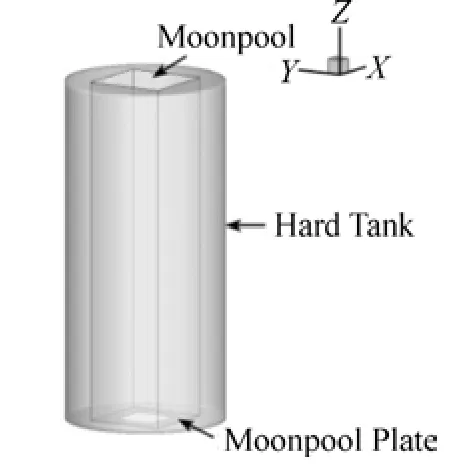
Fig.1 Hard tank geometry

Fig.2 Boundary conditions

Fig.3 Mesh grids for the whole fluid domain
2.3 User defined function
A user defined function (UDF) is adopted for the oscillation of the moonpool for the heave motion. The heave motion is defined as:

wherezis the heave displacement,Athe heave amplitude,andωthe heave circular frequency.
According to the empirical formula, the natural period of the moonpool fluid can be obtained (Guptaet al., 2008):

wherehis the depth of the water in the moonpool, andgthe acceleration of gravity.
In the simulations, the moonpool heave period isT=8s ,the amplitude of the heave motion isA=1m . The equation of the heave motion is built into the UDF program and then the heave motion of the platform is controlled by the compiled UDF.
2.4 Calculation conditions
The moonpool guide plate is equivalent to two shapes,namely the square-ring and crisscross. The outlines of the moonpool guide plates are shown in Fig.4. The square-ring is used for comparing the theoretical analysis and the crisscross corresponds to the engineering practice. The three-dimensional models of the Spar platform are established with the opening ratios of 0.1, 0.3, 0.5 and 0.7,respectively. The definition of the opening ratio is the moonpool opening area divided by the bottom area of the moonpool.
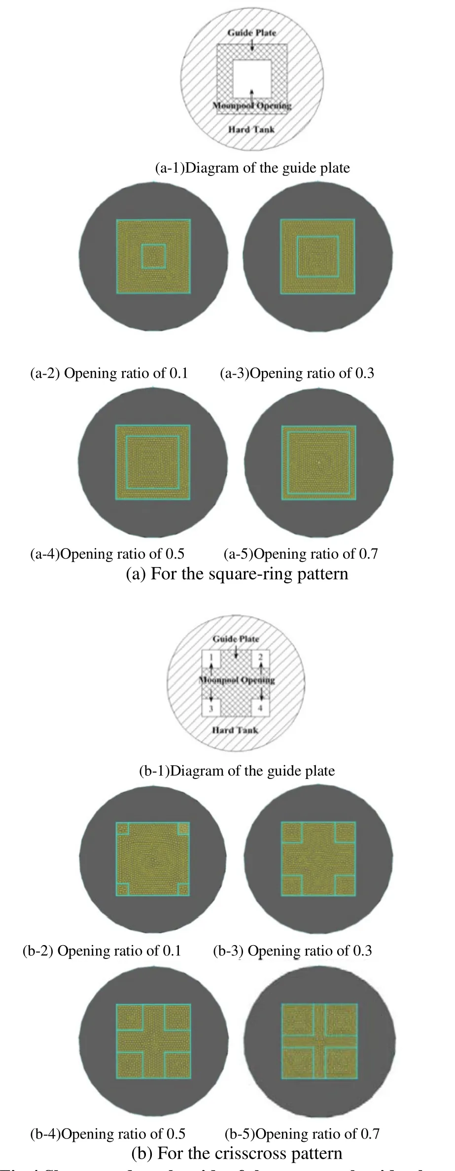
Fig.4 Shapes and mesh grids of the moonpool guide plate with different opening ratios
2.5 Numerical method
The pressure-based method is adopted for solving the Navier-Stokes equation. The free surface of the sea water is numerically simulated by the VOF (Volume of Fluid) model implemented in FLUENT and the option of Channel Flow is opened. The viscous model used is the standardk-εmodel.The method of pressure-velocity coupling is PISO. The discretization equation is established with the second-order upwind scheme (Wang, 2004). Based on the minimal size of the grids and the relationship between the velocity of the platform and the time step, the calculation time step is assumed to be 0.02 s.
3 Calculation results and analysis
The heave motion is imposed on the Spar platform by the compiled UDF and the corresponding motion curves are shown in Fig.5.
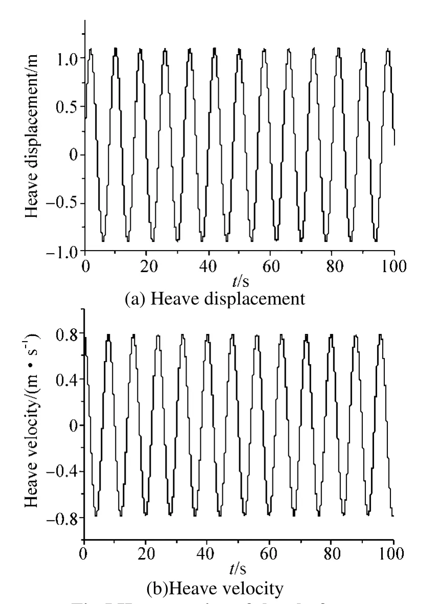
Fig.5 Heave motion of the platform
According to the two different shapes of the moonpool guide plates, the simulation results on the motion of the moonpool fluid inside are presented and then the effects on the mechanical characteristics of the moonpool guide plate are analyzed.
3.1 Moonpool guide for plate loads
The loads on the guide plate at the bottom of the moonpool can be obtained. For the convenience of comparison, it is divided into square-ring areas and crisscross areas of the guide plate and then the loads are normalized to unity, as shown in Fig.6.
In Fig.6, curves with ‘○’, ‘▲’, ‘■’ and ‘×’ represent the opening ratios of 0.1, 0.3, 0.5 and 0.7, respectively. Fig.6 shows that the amplitude of the load per unit area on the guide plate reduces with time. By averaging the amplitude of the load per unit area in each calculation condition, the curves of the average amplitude as a function of opening ratio are shown in Fig.7.
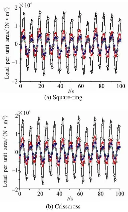
Fig.6 The load per unit area of the moonpool guide plate
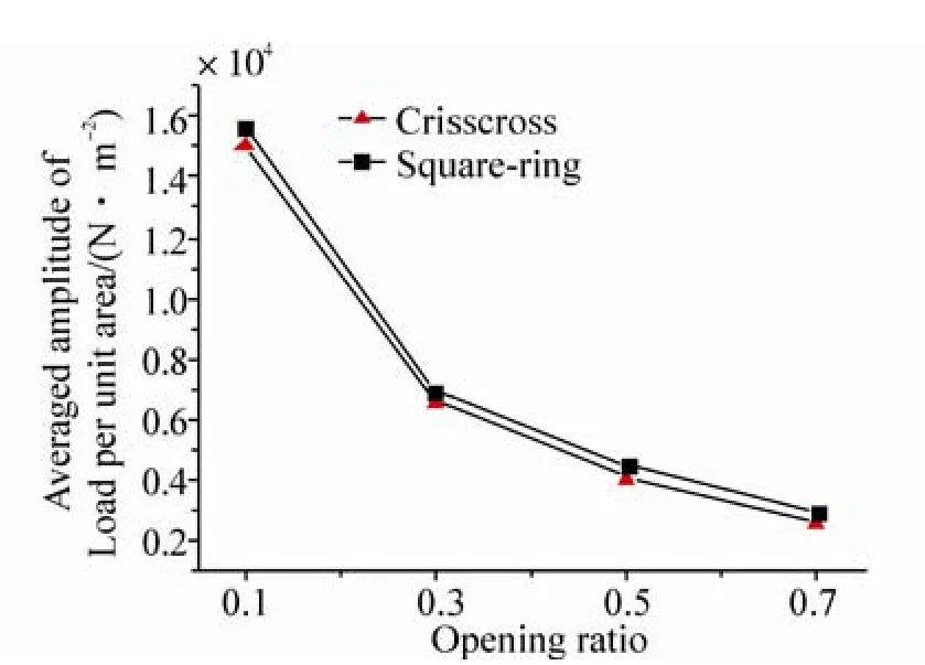
Fig.7 The changes of the average load amplitudes with increasingly opening ratios
Fig.7 shows that, for the same shapes of the moonpool guide plates, as the opening area increases, the average amplitude of the load on the guide plate reduces with a gradually decreasing rate. With the same opening ratio, the average amplitude of the load on the square-ring guide plate is slightly higher than the average amplitude of the load on the crisscross guide plate.
Based on the Holmes’s results (Samuel Holmes, 2008),the calculation results in this paper will be verified.

Fig.8 History of the loads on the moonpool guide plate
The definition of the blockage ratio is the moonpool guide plate area divided by the bottom area of the moonpool. As a result, the blockage ratio and the opening ratio are just the opposite.
In Fig.8 (a), for the case of the crisscross shape and the opening ratio of 0.3, the history of the loads on the guide plate at the bottom of the moonpool is presented. Fig.8 (b)shows that, when the shape of the guide plate is crisscrossed and the blockage ratio is 0.71, the loads curve can also be approximately regarded as a sinusoid with the initial phase.In addition, the two results above have the same order of magnitude of 106.

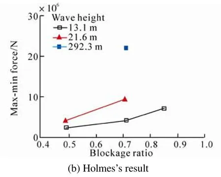
Fig.9 Loads on the moonpool guide plate vs. opening ratio and blockage ratio
Fig.9(a) illustrates that loads on the guide plate are reduced with a gradually decreasing rate when the shape of the guide plate is crisscrossed. Fig.9(b) shows that the moonpool plate loads increase rapidly by increasing the moonpool guide plate blockage ratio when the shape of the guide plate is crisscrossed and the wave height is 13.1 m.The curves of the two results in Fig.9(a) and Fig.9(b) have the same change trend. Additionally, the two results have the same order of magnitude of 106. Therefore, we can draw a conclusion that the two results are basically consistent and the calculations of the loads in this paper are reliable.
3.2 Motion of the free surface
The center point of the free surface is monitored in order to analyze the motion of the free surface in the moonpool.The vertical elevation and velocity of the monitoring point can then be obtained for each of the calculation conditions,as shown in Fig.10 and Fig.11. The meanings of the curves in Fig.10 and Fig.11 are the same as in Fig.6.

Fig.10 Vertical motion of the monitoring point for the case of the square-ring
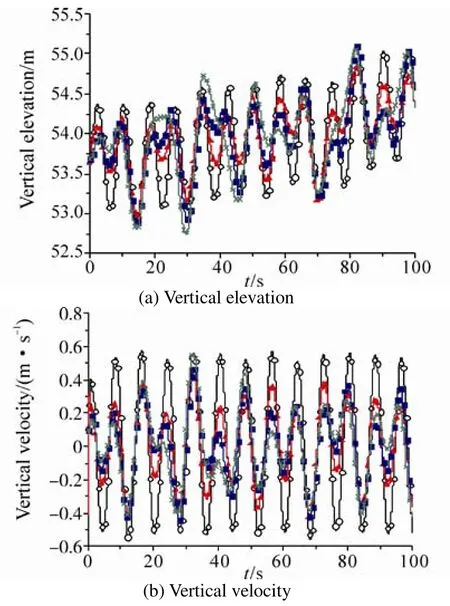
Fig.11 Vertical motion of the monitoring point for the case of the crisscross
Fig.10 and Fig.11 show that when the opening ratio is 0.1,the fluid in the moonpool basically moves with the motion of the Spar platform. As the opening area increases, the relative motion of the fluid particle in the moonpool becomes more significant. The elevation and velocity amplitude of the monitoring point is less than that of the Spar platform, but in a more complicated form. Comparing the shapes of the square-ring and crisscross, with the change of the opening area, the change of motion form of the monitoring point for the case of the crisscross is more obvious.
3.3 Mass flow rate
The mass flow rate is introduced to study the phenomenon of the fluid exchange at the opening of the moonpool guide plate. The mass flow rate through a surface is computed by summing the product of the density with the dot product of the facet area vector and the facet velocity vector:

whereρis the density of sea water,vthe velocity of the fluid particle, andAthe area of the moonpool opening.
In this study, the mass flow rate is the mass of the fluid which passes through the opening surface per unit of time.For the convenience of comparison, according to the following formula (4), the mass flow rate is divided by the corresponding area of the opening and then is converted to the per-unit-area mass flow rate following the formula. The curves of time series of the per-unit-area mass flow rate are shown in Fig.12. The meanings of the curves in Fig.12 are the same as in Fig.6.

Fig.12 illustrates that for the square-ring guide plate, the per-unit-area mass flow rate is maximized with the opening ratio of 0.3, and when the opening ratios are 0.1 and 0.7, the per-unit-area mass flow rate is reduced. For the crisscross guide plate, when the opening ratio is 0.7, the per-unit-area mass flow rate reaches the maximum value and when the opening ratios are 0.1 and 0.3, the per-unit-area mass flow rate is smaller. Therefore, the mass flow rate of the opening has a close relationship with the opening form of the moonpool guide plate. According to the following formula(5), by averaging the amplitude of the per-unit-area mass flow rate in each calculation condition, the average amplitudes are obtained as shown in Table 2 and plotted in Fig.13.


Fig.12 Per-unit-area mass flow rate of the moonpool opening
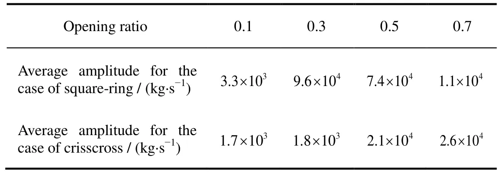
Table 2 Average amplitude of the per-unit-area mass flow rate

Fig.13 The changes of average amplitudes of the per-unit-area mass flow rate with increasingly opening ratios
Table 2 and Fig.13 further suggest that the per-unit-area mass flow rate of the opening has a close relationship with the opening form of the moonpool guide plate. Comparing the two forms of the moonpool guide plates, a higher per-unit-area mass flow rate is obtained with the square-ring opening when the opening area is small.
4 Conclusions
The vertical motion characteristics of the moonpool fluid for the Truss Spar platform is studied based on the CFD software FLUENT in this paper. The analysis focuses on the impacts of the different shapes and opening area of the guide plate on the vertical motion characteristics of the moonpool fluid. The results show that:
1) When the platform is subjected to a periodic heaving motion, the load on the moonpool guide plate presents a rule of periodic change. The amplitude of the per-unit-area load on the guide plate increases as the moonpool plate opening area decreases.
2) As the moonpool plate opening area increases, the average amplitude of the load on the moonpool guide plate reduces nonlinearly with a decreasing rate.
3) When the opening ratio is small, fluid in the moonpool basically moves with the motion of the Spar platform. A more significant relative motion of the fluid particle in the moonpool is observed as the opening area increases, with a more obvious change of motion form for the case of the crisscross shape.
4) The mass flow rate of the opening has a close relationship with the opening form of the moonpool.
Acknowledgement
The authers give thanks to the Tianjin University High Performance Computing Center for providing the high-performance computing services.
Faltinsen OM, Rognebakke OF, Timokha AN (2007).Two-dimensional resonant piston-like sloshing in a moonpool.J. Fluid Mech., 575, 359-397.
Gupta H, Blevins R, Banon H (2008). Effect of moonpool hydrodynamics on Spar heave.Proceedings of the ASME 27th International Conference on Offshore Mechanics and Arctic Engineering, Estoril, Portugal, OMAE2008-57264.
Holmes S, Gebara J, Magee A (2008). Centerwell water motions and hydrodynamic loading using viscous flow.Proceedings of the ASME 27th International Conference on Offshore Mechanics and Arctic Engineering, Estoril, Portugal, OMAE2008-57882.Kim MH, Ran Z, Zheng W (2001). Hull/Mooring coupled dynamic analysis of a truss spar in time domain.International Journal of Offshore and Polar Engineering, 11(1), 42-54.
Liu LQ, Tang YG, Wang WJ (2009). Unstability of coupled heave-pitch motions for spar platform.Journal of Ship Mechanics, 13(4), 551-556.
Liu LQ, Zhou B, Tang YG (2013). Study on the nonlinear dynamic behavior of deep sea Spar platform by numerical simulation and model experiment.J. Vib. Control, DOI:10.1177/107754631 2472917.
Molin B (2001). On the piston and sloshing modes in moonpools.J. Fluid Mech., 430, 27-50.
Montasir OA, Kurian VJ (2011). Effect of slowly varying drift forces on the motion characteristics of truss spar platforms.Ocean Engineering, 38(13), 1417-1429.
Nakayama A, Okamoto D, Takeda H (2010). Large-eddy simulation of flows past complex truss structures.Journal of Wind Engineering and Industrial Aerodynamics, 98(3), 133-144.
Purath BT (2006).Numerical simulation of the Truss spar ‘Horn Mountain’ using couple. Master thesis, Texas A>amp;M University,Texas, 1-9.
Tang YG (2008).Ocean engineering structural dynamics. Tianjin,Tianjin University Press.
Tao LB, Lim KY, Thiagarajan K (2004). Heave response of classic spar with variable geometry.Journal of Offshore Mechanics and Arctic Engineering, 126(1), 90-95.
Wang FJ (2004).Analysis of Computational Fluid Dynamics.Beijing, Tsinghua University Press.
Wang Y, Yang JM, Xiao LF (2008). Review on the study of Spar platform, TTR and buoyancy can.Ocean Engineering, 26(2),140-146/154.
Yang M, Teng B, Ning D, Shi Z (2012). Coupled dynamic analysis for wave interaction with a truss spar and its mooring line/riser system in time domain.Ocean Engineering, 39, 72-87.
Yao XL, Kang Z (2007). Experimental research on flow induced oscillation of circle moonpool.Chinese Journal of Theoretical and Applied Mechanics, 39(3), 333-341.
Yiu F, Stanton P, Burke R (2010). Overview of deepwater and ultra-deepwater Spar risers.Proceedings of the ASME 2010 29th International Conference on Ocean, Offshore and Arctic Engineering, Shanghai, China, OMAE2010-20159.
杂志排行
Journal of Marine Science and Application的其它文章
- Hard Foulers Induced Crevice Corrosion of HSLA Steel in the Coastal Waters of the Gulf of Mannar (Bay of Bengal), India
- An Approximate Method for the Surge Response of the Tension Leg Platform
- Dynamic Coupled Analysis of the Floating Platform Using the Asynchronous Coupling Algorithm
- Numerical Investigation of Mooring Line Damping and the Drag Coefficients of Studless Chain Links
- Floating Production Platforms and their Applications in the Development of Oil and Gas Fields in the South China Sea
- Bucket Group Effect of the Composite Multi-bucket Structure
