Dynamic Coupled Analysis of the Floating Platform Using the Asynchronous Coupling Algorithm
2014-07-30ShanMaandWenyangDuan
Shan Ma and Wenyang Duan
College of Shipbuilding Engineering, Harbin Engineering University, Harbin 150001, China
1 Introduction1
Deepwater floating systems consist of a floating platform,mooring and risers. As the oil and gas exploration continue to develop in deepwater areas, the interaction between floating platforms and mooring/risers become more pronounced. It has been long recognized that there is a need to develop the coupled analysis method to simultaneously solve the dynamic responses of the platform and mooring/risers. In this regard,Paullinget al.(1986) did the pioneering research. They extended the slender rod theory proposed by Garrett (1982) to simulate the tendons, as well as studied the dynamic response of the TLP platform coupled with the dynamics of extensible tendons. Ranet al. (1997, 2000) developed the coupled dynamic analysis program where the 3D second order potential flow theory is used to estimate the wave loads on floating platforms, the slender rod theory is used to model the mooring/risers, the flexible lines and the rigid body are connected together via springs and dampers and thus form a multiple DOF coupled dynamic system of equations. By solving the multiple DOF systems of equations, the coupled solution can be obtained. Lowet al.(2006) used the lumped mass method to simulate the dynamic response of the mooring. They used springs to connect the floating body and lines, established the fully coupled analysis method in time domain and frequency domain. The authors investigated the LF hydrodynamic damping effect from mooring and the applicability of linearization of the damping and mooring restoring force. Rhoet al.(2007) applied the Newmark method for the time marching scheme of the FEM equations of the mooring/riser and the vessel. In that paper the coupled equations of the mooring/riser segments and vessel are solved alternatively at each time step. The mooring/riser and the vessel motion affect to each other in a way that the components of the forces at the segment ends are determined as a function of displacements and slopes of the vessel. On the contrary, the vessel motions are determined again by the nodal force at the segment ends of the mooring/risers. By iteration solution of the mooring/risers and vessel using the updated information of displacement from the vessel and nodal loads from mooring/risers, the displacement of the vessel and the nodal force from the mooring/riser can be matched to each other. In other words the coupled dynamic solution of the vessel and the mooring can be achieved by iteration of the two dynamic systems. Using this method, each of these lines can be solved separately. The computational efficiency could be improved by solving the dynamics of all the lines using a parallel algorithm.
In this paper, we use the idea of the asynchronous coupled algorithm proposed by Jinget al. (2011) to perform the simultaneous solution of the floating platform and mooring/risers. Via this method, the dynamic response of the platform and mooring/risers is solved in a separate module.They are coupled together by matching the information at the connection point. The final goal is to optimize the time step of the two dynamic systems with a different time scale and the computational efficiency of the coupled analysis is improved further using parallel computation of the mooring/risers.
The main focus of this paper is on the dynamic modeling of the floating vessel using the Euler angle to consider the nonlinear effects of motion on the rigid body equations.Additionally, we introduce how the vessel and mooring are coupled together using the idea of asynchronous coupling.The numerical results are checked and validated with the commercial software package.
2 The dynamic modeling of platform motion under environmental loads and mooring/risers
The platform is assumed to be undergoing 6DOF motions under the external environmental loads like wind, waves and currents forces. For a moored floating structure, the wave frequency oscillatory motions often exist together with the low frequency slow drift motions and they are also coupled to each other. In our numerical model these two types of motions are modeled and solved together.
In order to evaluate the motions of the platform, the translational momentum theorem is used at the mass center of the platform in the Earth fixed coordinate systemO−XYZ:
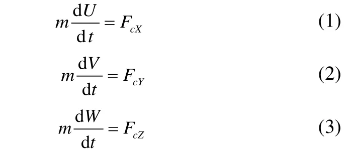
where the mass of the platform ism.U,VandWare the velocity components of the body at the center of gravity.FcX,FcYandFcZare the global external forces on the body at the center of gravity.
In order to evaluate the rotations of the body, the angular momentum theorem is used at the center of the mass in the body fixed coordinate systemG−xb ybzb.
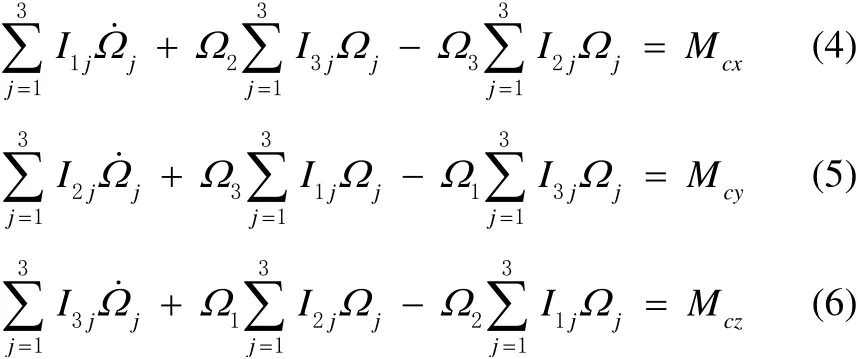
whereIij,i,j=1,3,2 represents the inertial moment matrix of the platform about the center of the mass in the body fixed coordinate system.jΩis the angular velocity component,Mcx,McyandMczare the external moments on the platform, respectively.
In order to express the platform displacement, the translational displacement of the body at the center of gravity areXo,YoandZoin the Earth fixed coordinate system. The Euler anglesα,βandγare introduced to express the rotation displacement of the rigid body which represents the roll, pitch and yaw motions, respectively. It can be demonstrated that the displacement vector satisfies the following motion differential equations:

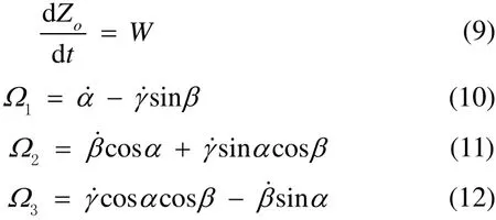
In Equations 1-6, the external force on the right hand side includes all the environmental loads from wind/wave/current and the structural loads from mooring/risers.Once we know these external forces, the six DOF responses of the platform can be determined using equations 1-12.
The hydrodynamic loads on the floating structures in waves include the radiation wave forces, wave exciting forces (incident wave forces plus diffraction wave forces together), hydrostatic restoring forces, and damping forces.
As for the radiation wave forces on the floating structure,based on the linear radiation analysis theory in time domain,they can be expressed in terms of the impulse response function:

whereµjiis the added mass matrix of the platform at infinite high frequency,ivthe 6 DOF velocity component of the platform, andKjithe radiation force retardation function due to the impulse motion of the body in theith direction. The integration includingKjireflects the accumulated effects of the radiation wave force due to the generated waves by the platform motions at previous time before the current time momentt.
The retardation functionKjican be converted from the hydrodynamic coefficient in frequency domain as follows:

whereµji(ω),λji(ω) are added mass and wave damping coefficients in frequency domain, respectively.Kjican be numerically evaluated using Eq. 14. The key factor for proper estimation is how to approximate the value of the radiation damping coefficient at high frequency in Eq. 14.Through the use of numerical investigation we obtain a stable method which can be used to estimate theKjieffectively.
As for the wave exciting forces on the floating structures,the second order potential flow theory is used. The total wave forces in irregular wave can be decomposed into first order wave forces and second wave forces as follows.
The first order wave force in irregular wave is expressed as:

whereζaj,k0j,ωjandεjrepresent the wave amplitude, wave number, circular wave frequency and random phase angle of thejthregular wave component, respectively.fja,jαare the amplitude and phase transfer function of the first order wave exciting force on the floating body due tojthregular wave component.XandYare the platform displacement along theOXandOYaxes at the center of gravity in the earth coordinate system.βis the wave heading of the incident wave relative to the yaw motion of the platform,β=180°is defined as the heading seas.
The second order low frequency (LF) wave force in the irregular wave can be expressed as:

whereTa jkandαjkare the amplitude and phase quadratic transfer function (QTF) of the difference frequency wave loads due to the interaction of the two wave components with the circular wave frequencyωjandωk, respectively.EspeciallyTa jjrepresents the mean drift force transfer function due to the interaction of the regular wave component with the circular frequencyjω.ajis the free surface wave elevation at the center of gravity in the Earth coordinate system which can be expressed using Eq. (18).

Due to the numerical complexity of calculating the second order low frequency wave loadsTa jk, Newman’s Approximation (Newman, 1974) is often used which can give a satisfactory estimation of LF wave loads when the water depth is deep and the horizontal resonant frequency of the moored structure is relatively low. Newman’s Approximation means that the LF wave loads QTF can be estimated using the mean drift loads. Based on the deviation in Chen et al. (2009), the Newman’s Approximation formula can be expressed as:

At higher sea states, the wave drift damping is the dominant hull damping component (Faltinsen, 1990), it is needed to consider this contribution. Presently the empirical formula originally derived on a 2D floating body at infinite water depth by Aranha (1991, 1994) and extened to 3D floating body by Clarket al. (1993) is applied.
With the current numerical model, the added mass and wave damping coefficients, first order and second order wave force transfer function in frequency domain are pre-calculated using three dimensional potential flow panel code Hydrostar (2010) and imported into the developed time domain simulation module.
3 The dynamic modeling of mooring lines and risers
There are multiple mooring lines and risers connecting to the platform. As stated previously each of these slender flexible members is solved separately. The slender rod theory (Pauling and Webster, 1986) is used here to simulate the dynamic response of mooring lines/risers. Based on this theory the FEM method is used to form the dynamic partial differential equations of mooring/risers in terms of unknown nodal displacement and axial force vector. A numerical module developed by Ma (2009) is applied here to solve the dynamic differential equations of the single lines/risers using some explicit integration algorithm once we know the boundary displacement time series of the platform at the connection point.
4 Asynchronous coupling algorithm between the platform and mooring/risers
In order to solve the platform motion and the mooring line/risers dynamic response together, several different methods have been proposed.
In this paper, we adopt the asynchronous coupled analysis,proposed by Jinget al.(2011). This method can be performed based on the separation of the platform motion and the motion of mooring/risers into two simulation modules. At the connection point between the platform and mooring lines/risers, the nodal forces and displacement has to be consistent in order to achieve the coupled solution. The main idea is introduced as follows.
As for the platform motion module, the dynamic response of the platform is solved based on the equations (1-12). We can write the motion equation in the following forms:

wherex(t) represents the displacement of the body at the center of gravity,

V(t)represents the translational velocity and angular velocity of the body respectively.

In order to implement the asynchronous coupling between the platform and mooring/risers, the Runge-Kutta (RK)fourth-order scheme is used to solve Equations 20-21. The displacement and velocity of the body can be predicted using the following formulas:
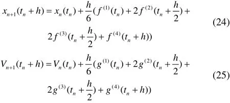
wherehis the time step to obtain the platform motions. In order to get the solution attn+h, one needs to know the vectorgat time momenttn,andtn+hwhich is related to the fluid forces on the body and the structural end loads from the mooring /risers. The fluid forces can be obtained based on the known or predicted displacement and velocity at these time moments like the wave forces given in equations 13-18. The structural loads have to be determined by solving the dynamic response of the mooring/risers using the slender rod theory. In the numerical model, the displacement and velocity at the connection point at time momentstn,and tn+ h on the platform is provided in order to be the boundary condition of mooring/riser dynamic analysis. By solving the mooring lines, the nodal reaction loads on the platform from mooring lines/risers can be obtained. In order to assure the simultaneous solution of the coupled dynamic response between the floating body and the flexible lines. The displacement of the body and the nodal structural loads at the connection point from the lines should be repeatedly convergent and matched to each other. By using the Runge-Kutta algorithm, the displacement and nodal force can be iterated, updated and corrected which can lead to the matched information exchange between the platform and mooring lines.
When using the RK algorithm to solve the dynamic response of the floating body, the nodal loads from the mooring/risers attn,and tn+ h need to be received. It is natural to choose the corresponding time step in the rod dynamic analysis module with the same floating body. Because of the dynamic response characteristics of the mooring/risers, the necessary time step of the lines is usually one order smaller than the necessary time step of the platform. So the time step of the coupled dynamic system between the platform and lines has to be determined as the minimum between the floating body and the mooring line. It means the synchronous coupling solution makes the time step of the platform module unnecessarily smaller for itself which causes the dynamic analysis of the platform motions to be unnecessarily longer.
Then the asynchronous coupling algorithm is used to improve the computational efficiency of the dynamic system.This algorithm platform and mooring/risers use their own optimized time step. It means that the dynamic response of the floating platform use the time stephwhile the rod dynamics use the smaller time stepdtapplicable to the response characteristics of the rod. Because the dynamic solution of the mooring/risers needs the input displacement at the top connection to the platform at its own time step, it is necessary to know the rod displacement time series at time intervaltn+kdtbetween the time step fromtntotn+h/2 and fromtntotn+h. In order to get the input displacement from the platform at these time intervals, the cubic interpolation polynomial is constructed using the platform displacement information attn,andtn+htime moment. Using the obtained interpolation function, the nodal displacement attn+kdttime moment is computed. Through this method, the nodal loads from the mooring/riser force on the floating body can be determined using the dynamic solution of the lines module at time momenttn+kdtwhich includes the moment attn,andtn+ .
During the numerical implementation of the dynamic coupling analysis using the asynchronous algorithm, it is found that the time step for the dynamic analysis of the mooring/risers should be limited in order to avoid the instability of the dynamic response.The maximum allowable time step is dependant on many factors such as the type of mooring system, the response amplitude of the platform motions,etc.andth
5 Numerical results
Based on the asynchronous coupling algorithm, we have developed a dynamic coupling program to solve the global motion response of the floating platform in wind, waves and currents.
In order to check our numerical model, the response of a classical SPAR platform (Steenet al., 2004) in irregular waves is simulated and compared with the commercial software AQWA. The main dimensions of the SPAR are listed in Table 1.
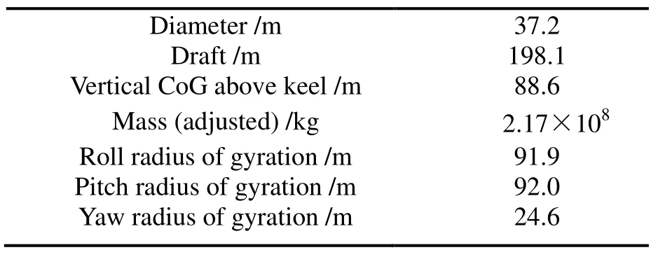
Table 1 The dimensions of the SPAR platform
The Spar platform is moored with 14 mooring lines. The mooring lines are uniformly spread and each of them is composed of three components of chain-wire-chain. Fig. 1 shows the layout configuration of the whole mooring system.Table 2 presents the parameters of the mooring lines.

Table 2 Parameters of the mooring lines
The asynchronous coupling algorithm developed in our numerical model is used to simulate the dynamic coupled response of SPAR with mooring lines. The water depth is 914.4 m. The numerical simulation time is three hours, the time step of the dynamic solution of the platform is 0.3 s,while the time step of the dynamic solution of the mooring lines is 0.05 s. Each mooring line is divided into 25 elements in the dynamic analysis using the FEM numerical method.The simulation is performed at heading seas. The JONSWAP sea spectrum is used with a significant wave height of 12.19 m, a spectral peak period of 14.0 s and a peakedness factor ofγ=2.5. The response of the SPAR in head irregular waves is compared with the commercial software AQWA. During the comparison the irregular wave time history is generated in our numerical model and imported to the AQWA software in order to ensure both of the numerical models have the same incident wave time history.
Figs.2-3 show the time history comparison of longitudinal and vertical radiation forces. In both our developed code and AQWA software, the radiation forces are calculated using the impulse response function as shown in Eq. 13. The results agree quite well, which shows that the radiation force in our program has been estimated properly using the impulse response function method.
Figs. 4-5 show the longitudinal first order and second order low frequency wave forces of the SPAR. The second order wave forces are estimated using Newman’s Approximation according to Eq. (19). It is demonstrated from the comparison that we have correctly modeled the wave forces.
Figs. 6-8 present the surge, heave and pitch motions. At the present case it should be noted that the effects of the second order low frequency wave force are not considered on for the heave and pitch motion in both our programs and the AQWA software for the convenience of the comparison.Generally, the results of our developed code agree quite well with the results from AQWA. The only exception is that the peak value of the surge motion in our code is a little larger than that of the AQWA software. The reason is probably that the hydrodynamic damping of the LF SPAR platform is relatively small and the damping level is a little different from the contribution of the wave drift damping effect between these two codes.
Figs. 9-11 give the mooring tensions of the No. 1, 4 and 8 mooring lines at fairleads. Our numerical results show quite consistent time history with that of the AQWA software.From the results it is seen that the dynamic responses of the mooring system in our program has been modeled properly and the asynchronous algorithm has been performed with a good precision on both platform motions and mooring line tensions.

Fig. 1 The layout configuration of the SPM system
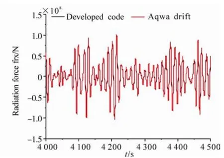
Fig. 2 The longitudinal radiation force comparison
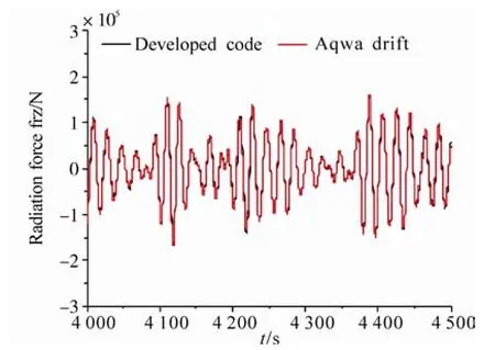
Fig. 3 The vertical radiation force comparison
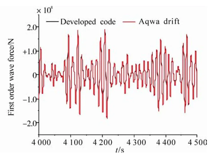
Fig. 4 The longitudinal first order wave force comparison
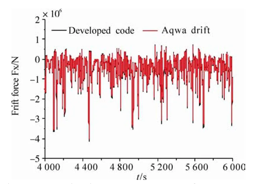
Fig. 5 The longitudinal second order low frequency waveforce comparison using Newman’s Approximation

Fig. 6 Surge motion of SPAR platform in head seas
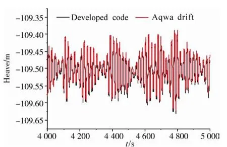
Fig. 7 Heave motion of SPAR platform in head seas
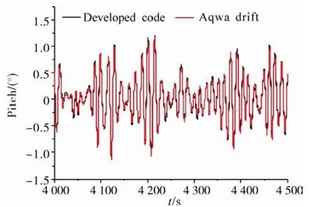
Fig. 8 Pitch motion of SPAR platform in head seas
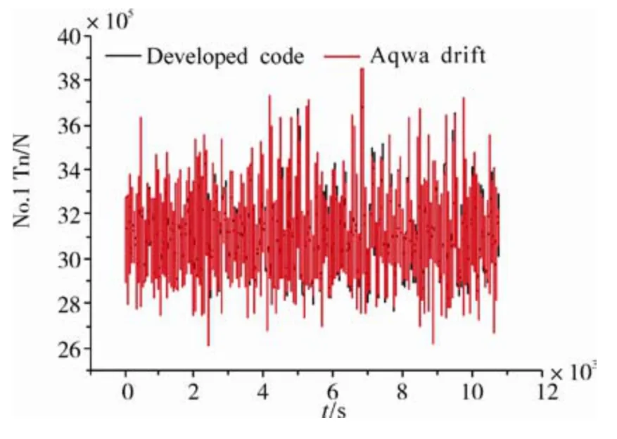
Fig. 9 #1 mooring line tension of SPAR platform at fairlead in head seas
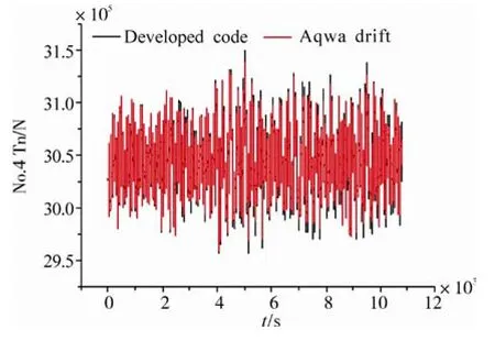
Fig. 10 #4 mooring line tension of SPAR platform at fairlead in head seas
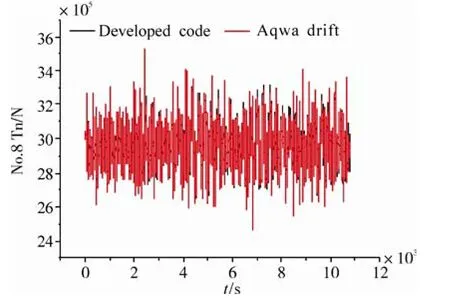
Fig.11 #8 mooring line tensions of SPAR platform at fairlead in head seas
6 Conclusion
This paper discusses a numerical model for performing the dynamic coupled analysis of the moored floating platform and mooring/risers. The emphasis is on the modeling of platform motions in waves. How the asynchronous coupling algorithm is achieved is also introduced. Through the use of a numerical comparison with the AQWA software package, it can be concluded that the dynamic modeling of the platform motion and mooring tensions, as well as the asynchronous coupling algorithm between the platform and mooring/risers has been properly established.
Acknowledgements
In the current research work, Prof. Webster W.C., Prof.Ma Q.W., Dr. Chen X.B. gave the authors a lot of beneficial help and advice, their contributions to this research work is greatly appreciated.
This work is part of the research project “coupled motion and external environmental loads analysis of deepwater floating structures,” which is sponsored by the Ministry of Industry and Information Technology of China. The financial support from the National Natural Science Foundation (Grant No.51109040), Young Faculty Academic Supporting Program of Heilongjiang Province (Grant No.1252G017), “111 project” foundation (Grant No.B07019) is also gratefully acknowledged.
Aranha JAP (1991). Wave groups and slow motion of an ocean structure.6th International Workshop on Water Waves and Floating Bodies, Woods Hole, MA, USA, 5-8.
Aranha JAP (1994). A formula for “Wave damping” in the drift of a floating body.J. Fluid Mechanics, 275, 147-155.
Bureau Veritas (2010). Hydrostar for experts user manual.
Chen XB, Rezende F (2009). Efficient computations of second order low frequency wave load.Proceedings of OMAE 2009,Honolulu, USA.
Clark PJ, Malenica S, Molin B (1993). An heuristic approach to wave drift damping.Applied Ocean Research, 15, 53-55.
Faltinsen OM (1990).Sea loads on ships and offshore structures.Cambridge University Press.
Garrett DL (1982). Dynamic analysis of slender rods.Journal of Energy resources technology.Transactions of ASME, 104,302-307.
Jing X, Webster WC, Xu Q, Lambrakos K (2011). Coupled dynamic modeling of a moored floating platform with risers.
Proceedings of the ASME 30th Inter. Conference on Ocean,Offshore and Arctic Engineering, Rotterdam, Netherlands,OMAE2011-49553.
Low YM, Langley RS (2006). Time and frequency domain coupled analysis of deepwater floating production systems.Applied Ocean Research, 28, 371-385.
Ma G (2009). Dynamic research of deepwater mooring line and riser based on elastic rod theory. Master Thesis, Harbin Engineering University, Harbin.
Newman JN (1974). Second-order, slowly varying forces on vessels in irregular waves.International Symposium on the Dynamics of Marine Vehicles and Structures in Waves, London,Mechanical Engineering Publications Ltd, UK, 182-186.
Pauling JR, Webster WC (1986). A consistent large-amplitude analysis of the coupled response of a TLP and tendon system.Proc. 5th OMAE Conf., Tokyo, Japan, 3, 126-133.
Ran Z, Kim MH (1997). Nonlinear coupled responses of a tethered spar platform in waves.International Journal of Offshore Polar Engineering, 7(2), 111–8.
Ran Z (2000).Coupled dynamic analysis of floating structures in waves and current. PhD Thesis, Texas A>amp;M University,College Station.
Rho JB, Korobkin AA, Jung JJ, Shin HS, Lee WS (2007). Coupled analysis of deepwater floating system including VIV in time domain.Proceedings of the 26th Inter. Conf. on Offshore Mechanics and Arctic Engineering, San Diego, California, USA,OMAE2007-29523.Steen A, Kim MH, Irani M (2004). Prediction of Spar responses:model tests vs. analysis.Offshore Technology Conference,Houston, TX, USA, OTC16583.
杂志排行
Journal of Marine Science and Application的其它文章
- CFD Simulation of the Vertical Motion Characteristics of the Moonpool Fluid for the Truss Spar
- Bucket Group Effect of the Composite Multi-bucket Structure
- Floating Production Platforms and their Applications in the Development of Oil and Gas Fields in the South China Sea
- Numerical Investigation of Mooring Line Damping and the Drag Coefficients of Studless Chain Links
- FPSO Global Strength and Hull Optimization
- An Approximate Method for the Surge Response of the Tension Leg Platform
