Calculation of the Added Mass of a Liquid Tank’s Bulkheads
2014-07-30JunkaiZhuZheLinQiangLiuandLihuaZhang
Junkai Zhu, Zhe Lin,Qiang Liu and Lihua Zhang
1. School of Naval Architecture Engineering, Dalian University of Technology, Dalian 116024, China
2. School of Mechanical Engineering, Dalian University of Technology, Dalian 116024, China
3. Wison Offshore >amp; Marine Ltd., Shanghai 201210, China
1 Introduction1
Liquid tanks such as fresh water tanks and ballast water tanks are very common in ships and offshore structures. The vibrations of the liquid tank’s bulkhead plate belong to the ship’s local vibrations which have the potential to greatly damage the global ship, thus it is important to ensure the dynamic safety of these liquid tanks. The crucial part in the study on the dynamic behavior of liquid tanks is the computation of the structural added mass caused by fluid.This study originated from a trial voyage of a 319000DWT VLCC built by the Dalian Shipyard (DSIC). In the vibration test of the ship, the excessive vibration magnitude of a pair of transverse bulkheads was detected in a water tank close to the stern. This phenomenon led to our strategy for computing the added mass for the vibration analysis of the rectangular water tank.
The present methods recommended in the corresponding guidelines and materials to compute added mass are widely used in the engineering computation, for example the DNV Formula (Det Norske Veritas, 1983) and the map coefficient(Jing and Xia, 2011) from experiments. However, they are only suitable for computing the first set vibration of the plate immersed in an infinite fluid domain, and not for the bulkhead plate structure interacted with the inner fluid domain. With respect to this type of problem, the direct FSI wet mode method is always used for taking the effects of the fluid added mass into consideration. The numerical wet mode methods include two sorts: 1) Structure FEM—Fluid FEM; 2) Structure FEM—Fluid BEM. However, these methods would require some extra modeling effort and demand a lot of computing time. With consideration to these shortcomings, the added mass coefficient and the water level index formulas for the bulkhead’s vibration of rectangular tanks ware derived based on the dry mode theory and compared with the numerical ones.
2 Deduction of the theoretical solution
2.1 Added mass coefficient formula
The simplified model with reference to the real water tank size ratio and its ANSYS model are shown in Fig.1:

Fig. 1 The simplified model
First, ANSYS was utilized for the dry modal analysis. In order to facilitate the deduction of the theoretical solution,the bulkheads were assumed to be just steel plates without stiffeners as shown in Fig.1. In reference to the real ship, the geometry of the model is:L=3.2 m,B=12.75 m,H=9 m. Its thickness is selected to be 30 mm and the material properties are: Young’s modulusE=2×10¹¹Pa, Poisson’s ratioμ=0.3 and densityρ=7800kg/m3. The plate is modeled by the most frequently-used element, Shell63 (bending and membrane element) as shown in Fig.1. In order to simulate the actual boundary conditions, the decks extended out at lengthLalongxandydirections. Simply supported constraints were imposed at all edges. The analysis results of the first six sets are shown in Fig.2 and Table 1.
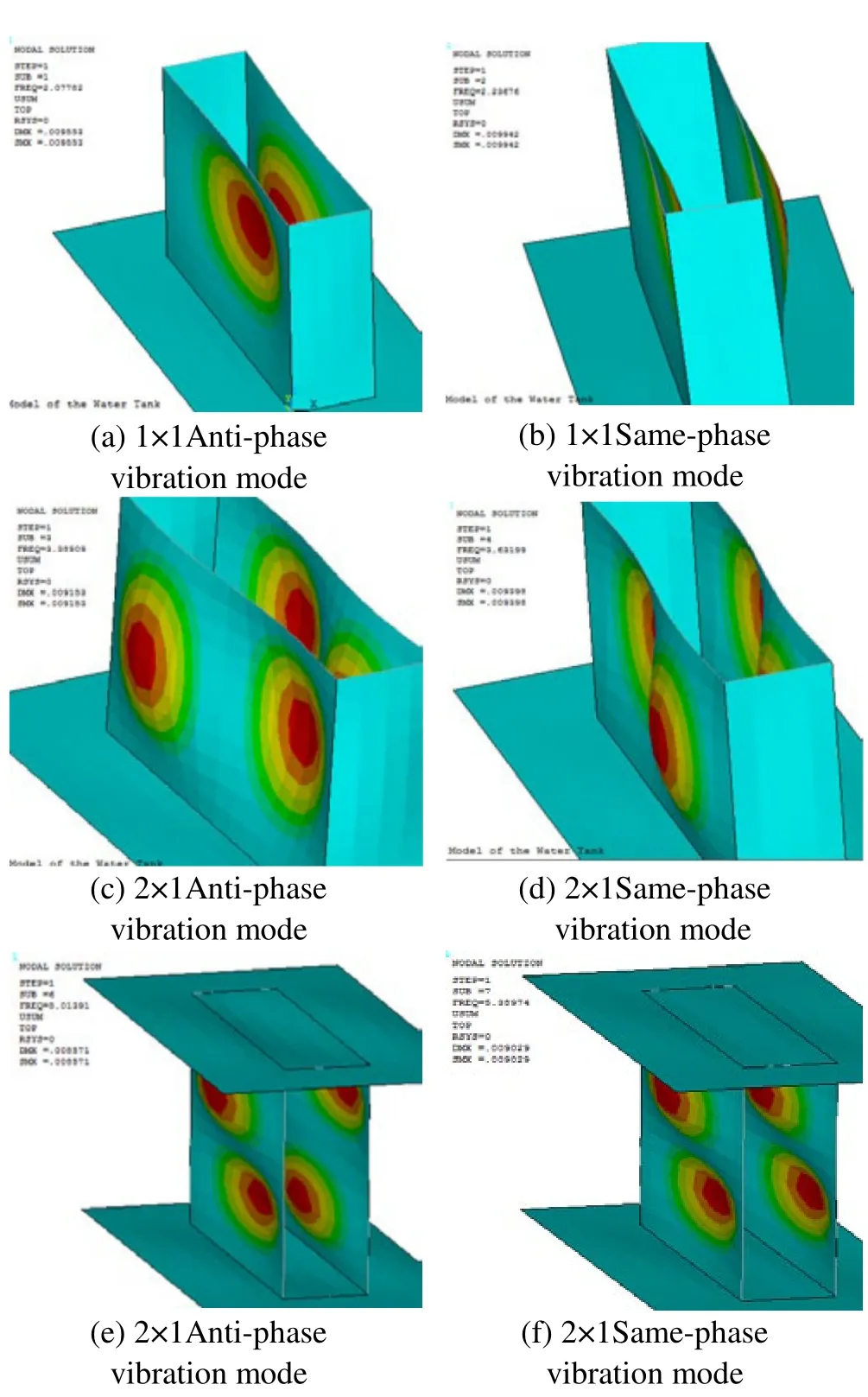
Fig.2 Results of the first six sets

Table 1 Results of the dry modal analysis
As can be seen from the mode shape figure, because of the simply supported BC around, the pair of transverse bulkhead’s dry mode with the same half wave number includes the same-phase style and the anti-phase one (the mode shapes of 1 × 1 vibration as shown in Fig.3):

Fig.3 Elevation plan of the vibration mode with the same half wave number
Based on the dry mode theory, the vibration modes of the bulkhead are assumed unchanged whether contacting water or not, and the vibration mode function is:
Same-phase:

Anti-phase:

The tank is firstly assumed to be filled with water (h=H),then the fluid potential function satisfies the three-dimensional Laplace equation throughout the fluid domain:

At the fluid–structure interface, the kinematic boundary condition is:

The fluid potential function can be derived from this definite problem. For same-phase vibrations, the vibration form of the No.1 and No.2 plates are anti-symmetrical, while for the anti-phase,they are symmetrical. The four walls around (decks and longitudinal bulkheads) are regarded as driven plates and the vibration modes are unknown, but the magnitude is relatively small. On the two active bulkheads the boundaries are assumed to be impermeable, so the constraint equations are:

The method of separation of variables was used to obtain the fluid potential function:

Substituting these boundary conditions into Eq. (3), we obtain the following expression:

Solving Eq. (7), we obtain theF(x):

From the anti-symmetry of the same-phase vibration and the symmetry of the anti-phase one, it is obvious thatA1=-A2for the same-phase andA1=A2for the anti-phase. Substituting these conclusions into Eq. (5) and Eq. (6), we obtain the following expressions:

Using the energy method for the added mass factorε,the added mass coefficient is easily obtained as follows:

wherekis the added mass coefficient required,fwis the frequency of the structure contacting with water,fis the frequency of the structure without the effects of water,Mais the added mass,Msis the structural quality,Twis half the kinetic energy of the fluid domain,Tsis the kinetic energy of the 1st transverse wall,mais the added water mass per unit area. The structural kinetic energy is a known quantity, and the fluid kinetic energy can be obtained as follows using Green’s second identity:

Substituting Eq. (11) into Eq. (10), added mass coefficientkcan be expressed as follows:

2.2 Water level index formula
When the tank is not filled with water (h>lt;H), the free surface boundary condition can be expressed as follows:

From the above Equation, it is obvious that this boundary condition is so related to the system frequency. According to the analysis made by Zhang(2004), when the free liquid sloshing frequency is close to the system frequency, the free surface boundary conditions have an impact on the frequency. So there will be some blurring errors if neglecting the free surface boundary conditions in the low frequency region, while this error can be ignored in the high frequency region. Though the added mass can reduce the vibration frequency of the system, compared with the free surface sloshing frequency, it is still high. In order to facilitate the derivation of the formula, free surface effects are neglected, and the impact of the water level only is considered.
Introducing a water level indexah, the definition of which is the ratio of the added mass at water levelhto the one with full water (h=H). The following is the process of its derivation:

Since the free surface condition was ignored, the conclusion from Eq. (12) also applied. Since ignoring the gravity effects of the free surface, the third quantity of Eq.(14) is not accurate and is actually too small to be considered.
Under these assumptions, it is clear thatahisTw’/ Twratio.
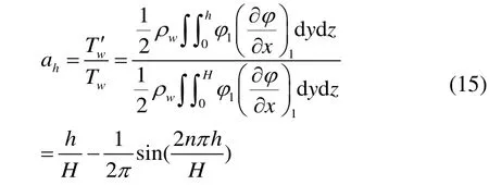
Substituting the depth coefficientahand the added mass coefficientkinto Eq. (13), we can easily obtain the natural frequency of the bulkheads at a certain level.

whereteis the equivalent plate thickness,f0the frequency of the dry-modal analysis, andf1the wet mode frequency.
Take a full tank for example: substituting the dry modal frequency listed in Table 1 and the tank size into Eq. (16),we can obtain the wet mode frequencies as listed in Table 2.
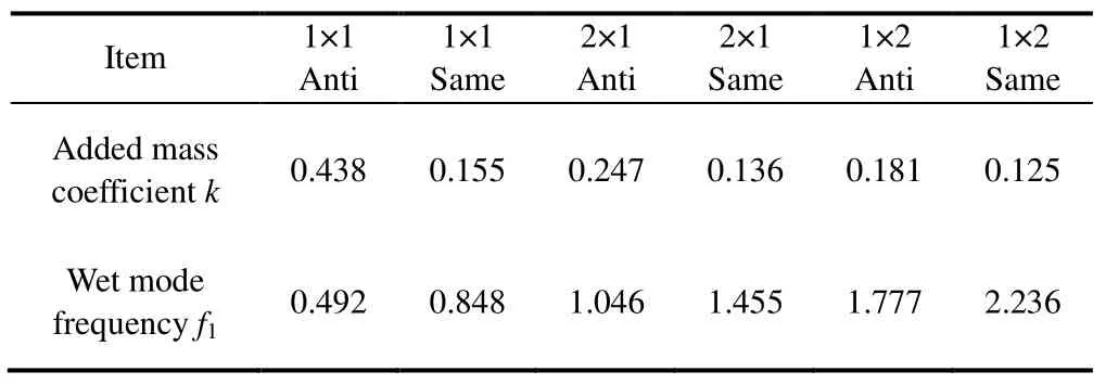
Table 2 Added mass coefficient and wet mode frequency
Table 3 is a comparison of the added mass coefficient from Eq. (12), the formula developed in the third literature(Kito Fumiki, 1960), the DNV formula and coefficient inquired from the map mentioned above.

Table 3 Comparison of the added mass coefficient
Note that the DNV formula actually is the result of Eq.(12) whenLis infinite, namely:

The comparison shows that the former two methods were similar for the same-phase vibration, while different for the anti-phase. However, compared to the infinite series expansion of the Kito Formula, our formula’s form is more efficient for practical use. In the developing process of the Kito Formula, the driven plates were assumed to be rigid which is different from the present method. And the latter two methods can only solve the vibration in open water, so the results derived by them are different.
3 Numerical solutions and comparison
3.1 The fully filled water tank
In this chapter, three numerical methods were used to solve this fluid-structure interaction system. They include the ANSYS /Fluid30, ANSYS/Fluid80 and NASTRAN Virtual Mass method. The former two are based on the structure-fluid finite element method and the last method is based on the structure finite element and fluid boundary element method. The differences of the former two methods based on the ANSYS platform are:
Fluid30 is a 3D acoustic fluid element used for modeling the fluid medium and the interface of FSI interaction problems. Typical applications include sound wave propagation and submerged structure dynamics. The governing equation for acoustics, namely the 3D wave equation, has been discretized taking into account the coupling of acoustic pressure and structural motion at the interface. The solid displacement-fluid pressure pattern is used: the solid element has three DOFs per node:translations inx,yandzdirections. The inner fluid element has one DOF of pressure per node, while at the interface,four degrees are available both for fluids and solids.
Fluid80, namely the 3D contained fluid element, is using the fluid/solid displacement pattern where the solids and fluids are both described by displacement. This element model is based on the Housner theory, in which fluid is deemed as the zero shear stiffness (shear-free) solid. Two nodes are to be set at the FS interface, one for fluids, the other for flexible structures. The normal translations of the two nodes are the same, while the tangential ones have no specific limits. This is called the slidable boundary condition.This method can more truly simulate the mode of the fluid itself, than the Fluid30 can. However, because of the increased DOFs of the inner fluid field, the dimensions of the unsymmetrical stiffness and mass matrix get larger and the computing procedure is more time-consuming.
A virtual fluid volume is produced during the process of NASTRAN VMM, just through creating the 2D FSI Element. The analysis methods include the wet and dry mode methods. The dry mode method based on the dry mode theory first computes the normal modes of the structure using BEM, and then adds the fluid mass to get the stiffness and mass matrix of the coupled system. The modeling and computing process of VMM is more convenient and efficient as compared to the former two methods.
Considering the contrast of the three numerical methods,the results from the ANSYS/Fluid80 is more accurate for the problem in this case as shown in Fig.4.
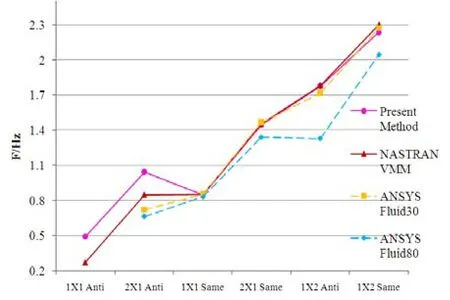
Fig.4 Comparison of the several methods
The present method was also compared respectively with the numerical ones:The present method has consistent results with NASTRAN and ANSYS/30, except 1×1 and 2×1 anti phase vibration. The frequency computed by ANSYS/80 is always lower. Since the method based on the Housner theory can take into account the mode of the inner fluid such as the sloshing mode, it is believed to be the most accurate one. The present method based on the dry mode theory which is not able to take into account the fluid influences on vibration mode, neglects the surrounding driven walls’ boundary conditions so this will result in certain errors, especially for the anti-phase. Results from the several methods as well as the relative errors between the present method and ANSYS/80 are listed in Table 4.
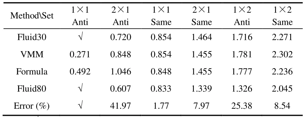
Table 4 Comparison of several methods
Fig.5 shows the modal shapes of ANSYS/30, ANSYS/80 and NASTRAN VMM. In order to observe the mode shape more clearly, the longitudinal bulkheads were concealed in the following pictures of ANSYS (a- j).
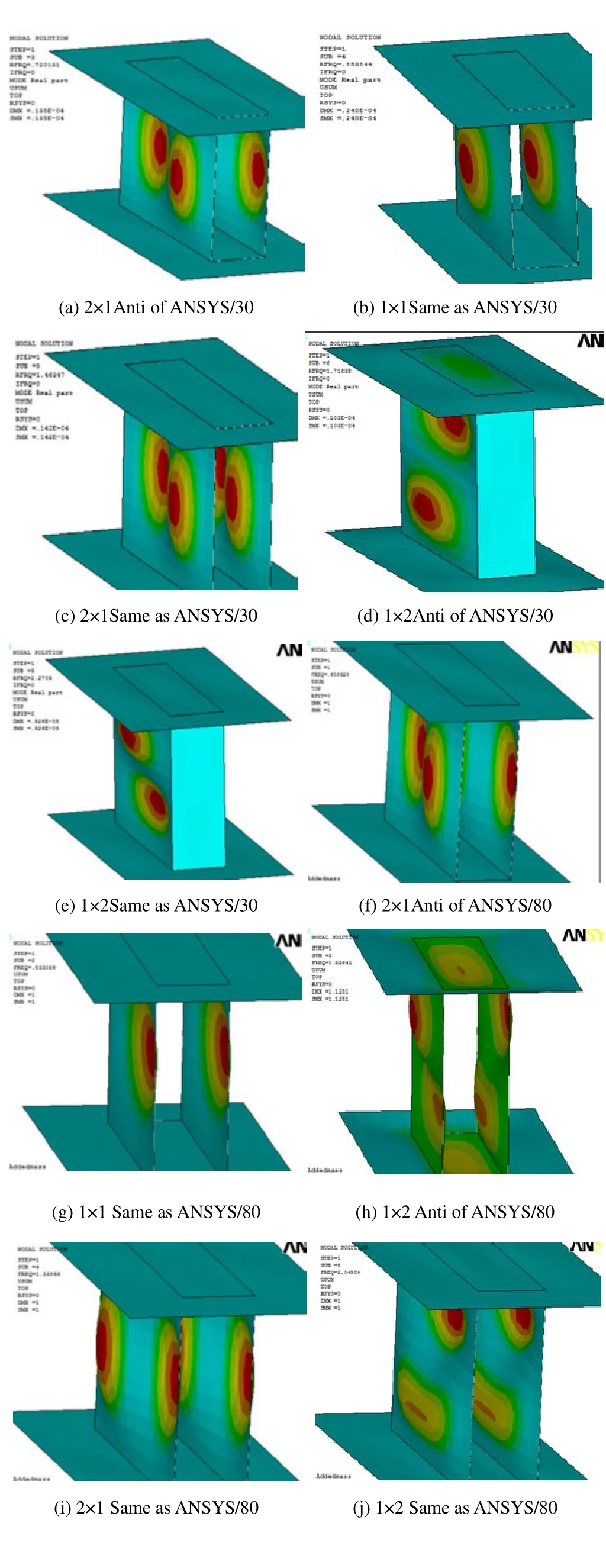

Fig.5 Mode shapes of each method
The specialties of the three numerical modal analyzing solutions to this sort of problem are listed in Table 5 in order to make a contrast.
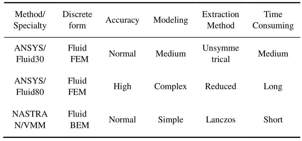
Table 5 Comparison of three numerical solutions
Table 5 shows that the process of using NASTRAN/VMM is very convenient and efficient although its accuracy is not the best. Therefore, this method is widely used for FSI numerical solutions to the actual engineering problem, for example it is recommended by ABS to solve the global ship vibration problem (American Bureau of Shipping, 2006). In the next chapter, the water level has been considered using ANSYS/80 and also the present method.
3.2 Influence of water levels
Pre-stressed model analyses to the original model of eleven water levels were performed with consideration to the gravity effects. The analysis results are shown in Fig.6 below.
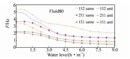
Fig.6 The solutions by ANSYS/Fluid80
The frequencies of the same-phase vibration by the present method are compared respectively with the ones by ANSYS/80 as shown in Fig.7.
According to the comparison, the trend of frequencies computed by the water level index formula of this paper is almost coincident with the one by Fluid80. This indicates that this serious of formulas is applicable to take into consideration the influence of the water level and has a certain level of accuracy for the same-phase vibration as compared to ANSYS/80 which can take into consideration the free surface sloshing effect.
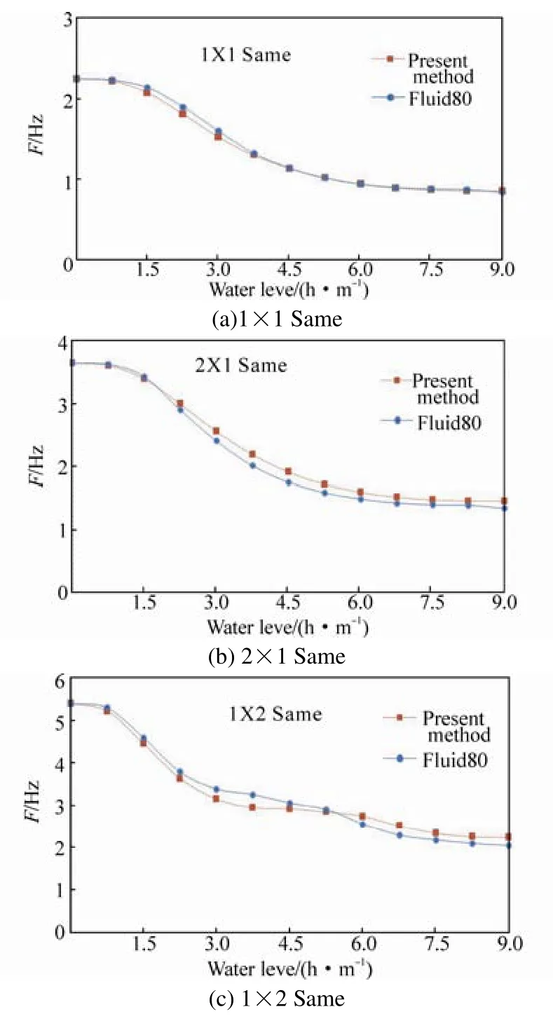
Fig.7 The comparison of the present method and Fluid 80(the same-phase)
4 The stiffened bulkheads
A stiffened water tank model was newly built, in which the size of the stiffeners and the thickness of the panels were set according to the real ship and the extending parts around were deleted as shown in Fig.8. Same as above, the dry mode analysis results of the new model are listed in Table 6:

Table 6 Dry mode frequency of the new model

Fig.8 The dry mode analysis results of the stiffened model
The water level influence was also considered using ANSYS/Fluid80 to calculate the natural frequency of the bulkheads in each water level shown as in Fig.9, with 9 water levels selected in total.
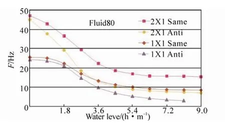
Fig.9 The solutions to the stiffened model by ANSYS/Fluid80
The results indicate that: under the 7.2 m water level, the vibration frequency for the 1×1 same-phase is 8.784 Hz,which is coincident with the 7th order excitation of the main engine in axis frequency 8.785 Hz. This leads to the resonant phenomenon stated above that the magnitude of the bulkheads’ vibration is significantly close to the water level which is identical with the data obtained from the trial voyage. The present simple method is also applicable and valid for the same-phase vibration, which is meaningful for the approximate computation in engineering. Fig.10 shows the comparison between the present method and ANSYS/Fluid80.
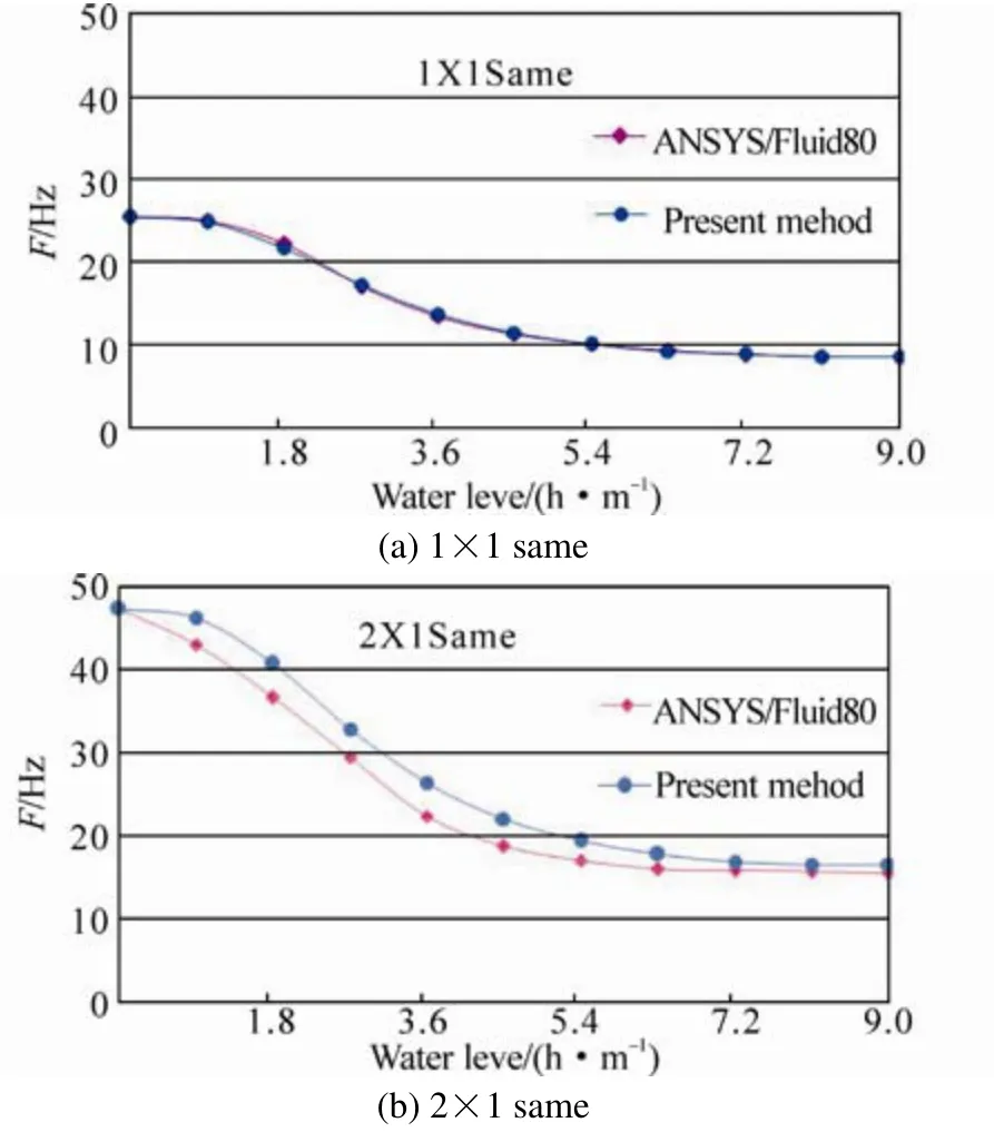
Fig.10 Comparison between the present method and ANSYS/ Fluid80
5 Conclusion
1) The added mass coefficient and water level index formula for the bulkhead’s vibration of rectangular tanks were developed. The formulas are the analytical solution to a simplified equalized model. They can be used for them×nsame anti-phase modal computation of the liquid tank’s bulkheads as a simplified method for the approximate computation in engineering.
2) The natural frequency computed by the present method was then compared with that used by the three numerical methods. The comparison indicates that ANSYS/80 is the most accurate among the numerical methods, and NASTRAN/VMM is the most applicable. Fortunately, the same-phase vibration added mass formula developed by this paper is in close accordance with ANSYS/80 and also the vibration test of the real ship. However, for the anti-phase vibration problem, this series of formulas still needs further discussion and improvement.
3) As the length of the tanks becomes larger compared to the width and height, the added mass of the same and antivibration tends to be the same. Ifm=1 andn=1, the formula becomes the DNV formula.
4) When using NASTRAN/VMM in this case, the dry mode and wet mode analyzing steps were adopted respectively. The procedure and results indicate that compared to the wet mode step, the dry mode step’s computing time is much shorter but the frequency is slightly higher, which is possibly one of the reasons why the frequency by the present method based on the dry mode theory is always higher than ANSYS/80. Specifically, the added mass achieved by the dry mode method is often lower.
Acknowledgements
This research subject was strongly supported by the Dalian Shipbuilding Industry Co., Ltd. The authors also are grateful and would like to thank my senior fellow apprentice, Doctor Jing-sheng Wang who is now working at the Plan Approval Center Shanghai of China Classification Society.
American Bureau of Shipping (2006). Guidance notes on ship vibration (Guideline). 40-42.
Det Norske Veritas (1983). Prevertion of harmful vibration in ships(Guideline). 51-52.
Ding Xiaotang, Liu Guang, Wang Shanshan, Jiang Yong (2011).Comparative study on dynamic behaviors of potential model and Housner model.Journal of Hydroelectric Engineering,30(6), 57-61.(In Chinese)
Esmailzadeh M, Lakis AA, Thomas M, Marcouiller L (2008).Three dimensional modeling of curved structures containing and/or submerged in fluid.Finite Elements in Analysis and Design, 44, 334-345.
Jing Xianding, Xia Lijuan (2011).Ship vibration. Shanghai Jiao Tong University Press, Shanghai, China, 132-137,180-182.(in Chinese)
Kerboua Y, Lakis AA, Thomas M, Marcouiller L (2008). Vibration analysis of rectangular plates coupled with fluid.Applied Mathematical Modeling, 31, 1570-1586.
Kito Fumiki (1960). On vibration of a rectangular tank filled with water.Journal of the Society of Naval Architects of Japan, 107,106-114,1960-07.
Liu Yunhe, Hu Baozhu, Yan Jianwen, Wang Kecheng (2002).Applicability of Houser model to a seismic characteristics calculation of aqueduct. Journal of Hydraulic Engineering, (9),94-99.(in Chinese)
Qu Fei, Li Kai, Li Xiangning, Yang Xionghui (2012). Effects of added mass caused by finite domain liquid on plate structure vibration.Chinese Journal of Ship Research, 7(3), 41-45.(in Chinese)
Siemens Product Lifecycle Management Software Inc (2011). NX Nastran 8 Advanced Dynamic Analysis User’s Guide(Guideline).
Zong Z, Lam KY (2000). Hydrodynamic influence on ship-hull vibration close to water bottom.Journal of Engineering Mathematics, 37(4), 363-374.
Zhang Shaoguang, Yang Dengfeng, Wang Deyu (2004). Vibration analysis of cylindrical shell filled with different height of fluid.China Offshore Platform, 19(3), 10-13.(in Chinese)
Zhang Shengming (1990). Added mass of underwater plate and beam stiffened plate in vibration.Journal of Hydrodynamics,5(1), 188-95.(in Chinese)
Zhao Deyou, Jing Weicheng, Zang Chunwang (1988).Global Vibration Prediction of Fishing Vessels. Dalian University of Technology Press, Dalian, Liaoning, China, 43-58.(in Chinese)
杂志排行
Journal of Marine Science and Application的其它文章
- CFD Simulation of the Vertical Motion Characteristics of the Moonpool Fluid for the Truss Spar
- Floating Production Platforms and their Applications in the Development of Oil and Gas Fields in the South China Sea
- Numerical Investigation of Mooring Line Damping and the Drag Coefficients of Studless Chain Links
- Dynamic Coupled Analysis of the Floating Platform Using the Asynchronous Coupling Algorithm
- Bucket Group Effect of the Composite Multi-bucket Structure
- An Approximate Method for the Surge Response of the Tension Leg Platform
