SINS in-flight alignment algorithm based on GPS for guided artillery shell
2014-07-19MEIChunboQINYongyuanYOUJinchuan
MEI Chun-bo,QIN Yong-yuan,YOU Jin-chuan
(College of Automation,Northwestern Polytechnical University,Xi’an 710129,China)
SINS in-flight alignment algorithm based on GPS for guided artillery shell
MEI Chun-bo,QIN Yong-yuan,YOU Jin-chuan
(College of Automation,Northwestern Polytechnical University,Xi’an 710129,China)
An SINS in-flight alignment algorithm is proposed for the guided artillery shell in which a low-cost MEMS IMU/GPS integrated system is equipped.The algorithm decomposes the attitude quaternion into three parts:inertial rate,separate Earth motion,and a constant quaternion.The first two parts are solved based on MEMS gyros’ measurement and GPS position information respectively,and the constant quaternion is solved by using Re-quest method.The errors and effective conditions of the proposed algorithm are discussed,and the Re-quest method is optimized and simplified.The results of Monte Carlo simulation show that the level errors are less than 0.2° (1σ) and the heading error is less than 0.4° (1σ) within 10 s,meeting the SINS alignment’s accuracy requirement of the guided artillery shell.
in-flight alignment;MEMS IMU/GPS;Re-quest;error analysis;sufficient condition
A growing number of smart munitions and guided artillery shells are equipped with the integrated low-cost MEMS IMU/GPS system.The initialization of the integrated system cannot be done before launch and all electronic systems on board will be shut down during launch because of the bursting acceleration.The launch shock initiates the thermal battery and the electronic systems become operational at an uncertain time with the shell having an uncertain attitude,uncertain position and moving at an uncertain speed.So the initialization of the system has to be done in-flight.With GPS aided,the position and speed are ready,but the attitude initialization known as in-flight alignment is still a tough task.
Currently,the in-flight alignment has been developed using nonlinear filtering methods,such as EKF[1],UKF[2]and PF[3],with nonlinear error models.Although these nonlinear approaches are effective,they all possess some or all of the drawbacks,such as large computation burden,sensitive to initial parameters and stability problem.The technique described in this paper is motivated by [4-7],and is a kind of deterministic method which is simpler and more robust than those nonlinear ones,but almost the same effective.
The outline of the remainder of the paper is as follows.First section presents coordinates and notations in use.The proposed in-flight alignment algorithm and its discrete realization are given in section Ⅱ.SectionⅢ discusses the algorithm error and section Ⅳinvestigates the sufficient condition of the proposed method.The last section shows the results of the Monte Carlo simulation and contains the main conclusion.
1 Coordinates and notations in use
Definitions of coordinates in use:
Navigation coordinates n:locally level geographic coordinates defined with itsZaxis upward along the local geodetic vertical,Yaxis north (and horizon) andXaxis east (and horizon);
Inertial navigation coordinates in:auxiliary inertial coordinates aligned with n at start-up of the alignment;
body coordinates b:located at the centroid of the vehicle,defined with itsYaxis forward along the longitudinal axis of the vehicle,Xaxis right and Z axis upward;
Inertial body coordinates ib:auxiliary inertial coordinates aligned with b at start-up of the alignment.
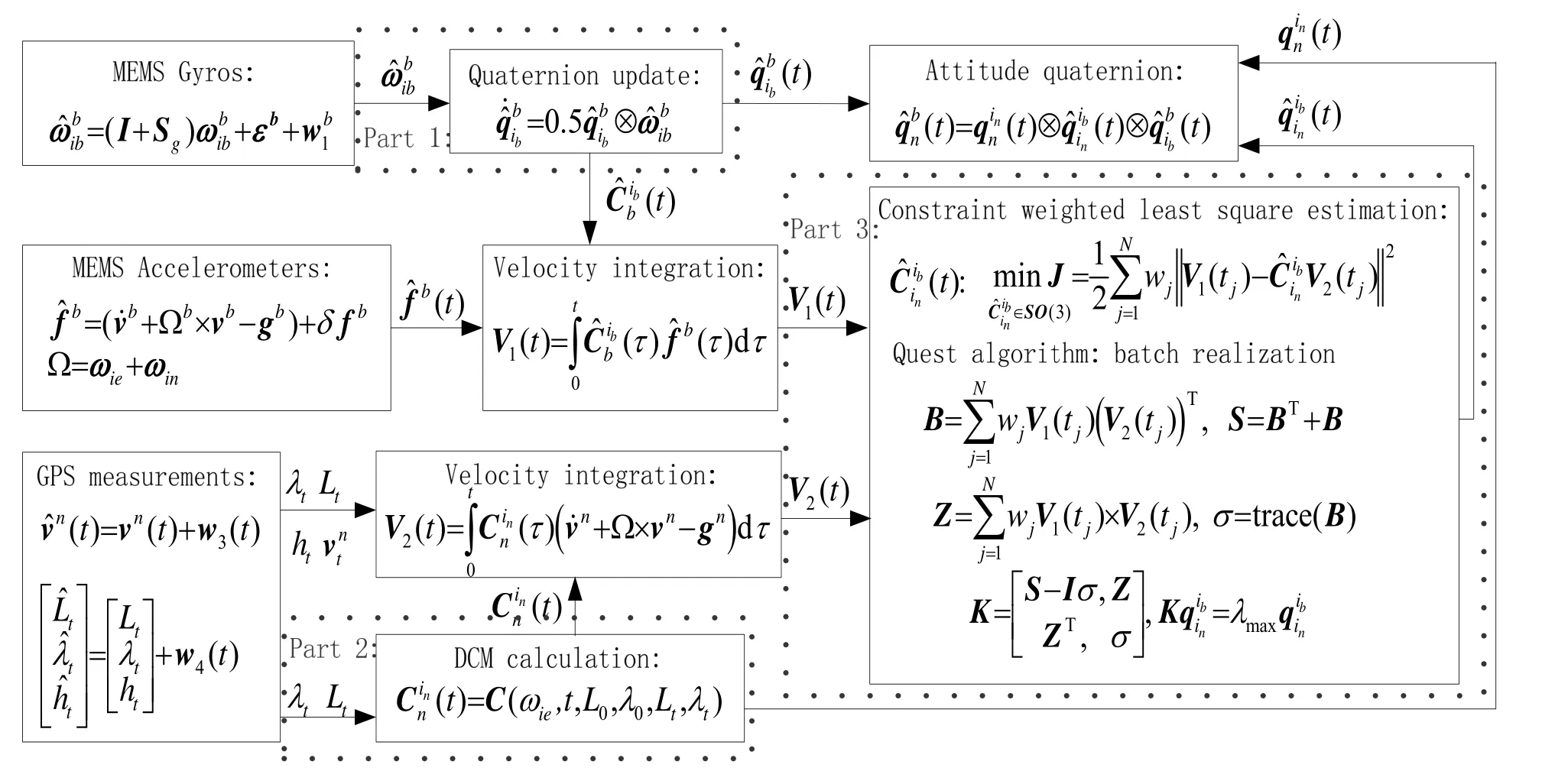
Fig.1 The flow chart of the complete in-flight alignment process
2 The in-flight alignment algorithm and its discrete realization
The in-flight alignment method is decomposed into three parts based on the decomposition of attitude quaternion as follow:

The flow chart of the complete in-flight alignment process can be illustrated in Fig.1.And its discrete realization is shown in Fig.2.
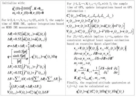
Fig.2 The discrete realization of the in-flight alignment algorithm
In Fig.2,the analytic expression of attitude matrixis:

Still,in Fig.2 there are two problems which are not explicitly explained.The first one is how to determine the optimal weights which directly influence the estimation accuracy of the Request algorithm.And the second one is how to search the maximum eigenvalue and the corresponding eigenvector of the given matrix,which is usually a time-consuming process and may diverges.Solutions of both problems will be provided in next section after the error analysis.
3 Error analysis,algorithm optimization and simplification
3.1 Error analysis of the proposed algorithm
Since the alignment is decomposed into three parts,the total alignment error should originate from the three calculations.
The ideal and real calculations of,and the calculation error definition can be described as:

The dynamic equation of the calculation error ofrepresented bycan be deduced from equation (3) as:

whereSis a diagonal matrix representing the scalar error of gyros;εis the random constant drift vector of gyros;w1is the measurement noise of gyros.
The time-varying attitude between the n and incoordinates can be equivalently represented byand,if define the small attitude error angle vectoras,


As illustrated in Fig.2,vectors used in Request algorithm,which arev1jandv2j,are normalized to be unit vectors,so the error in any one of them must to first order lie in the plane perpendicular to that vector,

We make the further approximation that the error vector has an axially symmetric distribution about the respective unit vector.In terms of the covariance matrices of the error vectors,the approximation reads,

where the brackets denote the expectation value;is the variance of a component along a direction normal tovij.

in which,


which are choose to minimize the original loss functionJin Fig.1.
3.2 Algorithm optimization and simplification
The problems provided at the end of section Ⅱwill be discussed in this subsection.
1) Optimal weights
As mentioned at the end of section 3.1,the optimal weights can be choose to minimize the original loss functionJin Fig.1 and assigned with equation (11).
Sincev1jandv2jare normalizations of the integration vectors,it’s necessary to consider the integration errors first.As illustrated in Fig.1 and Fig.2,the integration errors can be expressed as:

For a one time realization,the error vector δV1(t) is mainly a linear function of the constant bias and integration time,so the absolute value instead of covariance matrix of δV1(t) should be considered when to determine the optimal weights.On the other hand,the norm of the vectorV1(t) is also a linear function of integration time,so the accuracy of the normalized vectorv1jis almost constant which means that all vectors,,are the same accurate.As a result,v1jmay not be considered when to determine the optimal weights.
From equation (12),the covariance matrix of the vector δV2(t) should be,

and after normalization,the covariance matrix of the vector δv2jwill be,

Based on the above discussion,the optimal weights which will minimize the loss functionJin Fig.1 can be assigned

in which the latter one will be used in simulation.
2) Algorithm simplification
As aforementioned,searching for the eigenvector of the matrixKjis time-consuming and may diverges.Based on the following two truths[9-10],this problem can be avoided.
Truth 1:the relationship between the eigenvector and the corresponding eigenvalue is available

Truth 2:the maximum eigenvalue satisfies

which can be easily deduced from the deduction of the Quest algorithm.
Equation (17) indicates thatλmaxis unity if there exists an exact rotation which will rotate the reference vectors into the observation vectors.And it is to be expected thatλmaxwill deviate from unity by an amount on the order of half the mean square angular accuracy of the vectors.
The angular accuracy of the vectors can be illustrated with Fig.3.
Based on discussion in the optimal weights section,the angular accuracy of the vectors could be described as

Considering the ordinary case,
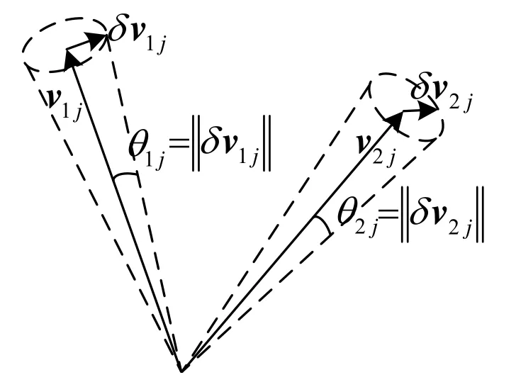
Fig.3 The angular accuracy of vectors

Thenλmaxwill differ from unity by an amount on the order of.
From equation (16) it is easy to see that if the matrixis nonsingular,thenymay be expanded in a Taylor series in.Thus,substitutingλmax≈1 in equation (16) yieldsyto this same accuracy,which corresponds to a computational error of 0.35 arc-minute.
4 Sufficient conditions
The proposed in-flight alignment algorithm will provide an accurate result if all three parts are effectively solved.If MEMS gyros and GPS all work correctly,then part.1 and part.2 will be solved effectively.But this is not sufficient for part.3.
Back to Fig.1,the attitude in part.3 may be solved using TRIAD algorithm with the least information which are two noncollinear vectors.This is the sufficient condition for part.3 to be effectively solved.
Based on the illustration in Fig.1 and Fig.2,it is obvious thatv1andv2are just different projections of the same vector on different coordinates,so the above mentioned sufficient condition may be equally described as,

Let’s rewrite the definition of the vectorV2(t) in Fig.1 as follow:

which directly indicates the two reasons for the direction of the integration vector changing:
1) Due to the earth rotation rate and the transport rate of the vehicle with relative to the earth,which are both small by an amount on the order of a few tens degrees per hour;
2) Due to the change of the vehicle’s acceleration with relative to the earth which may largely change the direction of the integration vectorV2(t).
Similar to the above two reasons,two facts about the special application should be noticed:
1) The MEMS gyros are low accuracy with measurement errors maybe larger than the summation of the earth rotation rate and the transport rate of the vehicle;
2) The maneuvers of the flying guided missiles or smart munitions are limited before the initialization.
Summarizing all above discussions will come to the conclusion that all possible constraint maneuvers should be performed to change the acceleration with relative to the earth in order to change the direction of the integration vector,so as to satisfy the sufficient condition for part.3 and for the complete in-flight alignment algorithm.
5 Simulation and conclusion
The test scenario simulates the speed-down phase of a gun-launched munitions with a parachute providing the acceleration.
In the speed-down phase,the trajectory of the launched munitions is described as follows:
Initial position:latitude 40°;longitude 108°;height 8000 m;
Initial velocity:500 m/s;
The pitch angle trajectory:-50+15sin(1.2πt) (deg);
The roll angle trajectory:30+5t(deg);
The heading angle trajectory:10+20sin(1.8πt)(deg);
The trajectory of the acceleration along the reverse direction of the velocity:40exp(-0.6t) m/s2;
The parameters of MEMS IMU and GPS are listed below (1σ):
Gyro random constant drift:10 (°)/h;
Gyro measurement noise:0.05 (°)/s;
Gyro scalar error:500×10-6;
Accelerometer random bias:5×10-3×9.8m/s2;
Accelerometer measurement noise:15× 10-3×9.8 m/s2;Accelerometer scalar error:500×10-6;
MEMS IMU sampling rate:100 Hz;
GPS velocity error:0.1 m/s (level),0.2 m/s(upward)
GPS position error:5 m(level);10 m(height);
GPS sampling rate:10 Hz.
Fig.4 ~ Fig.6 show the north,east and heading error angles respectively using the proposed in-flight alignment algorithm.
In Fig.4 ~ Fig.6,the mean and standard deviation of the alignment error are calculated from 100 runs with random measurement error.
The comparative result of the simulation is listed in table 1.
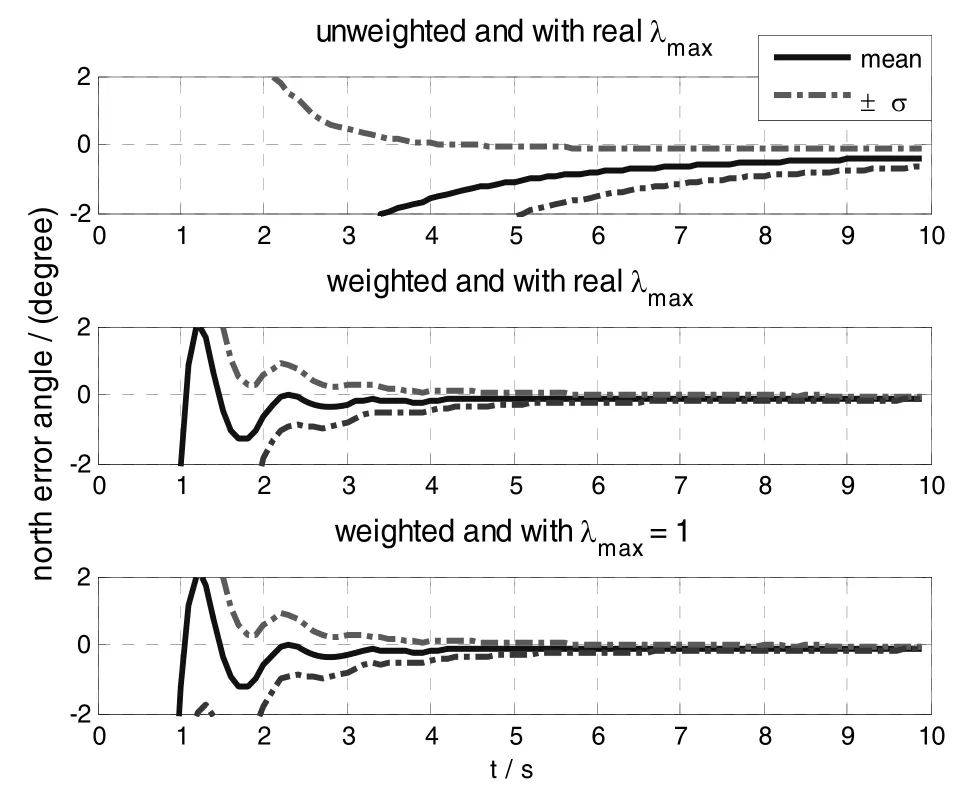
Fig.4 North error angle of the alignment algorithm
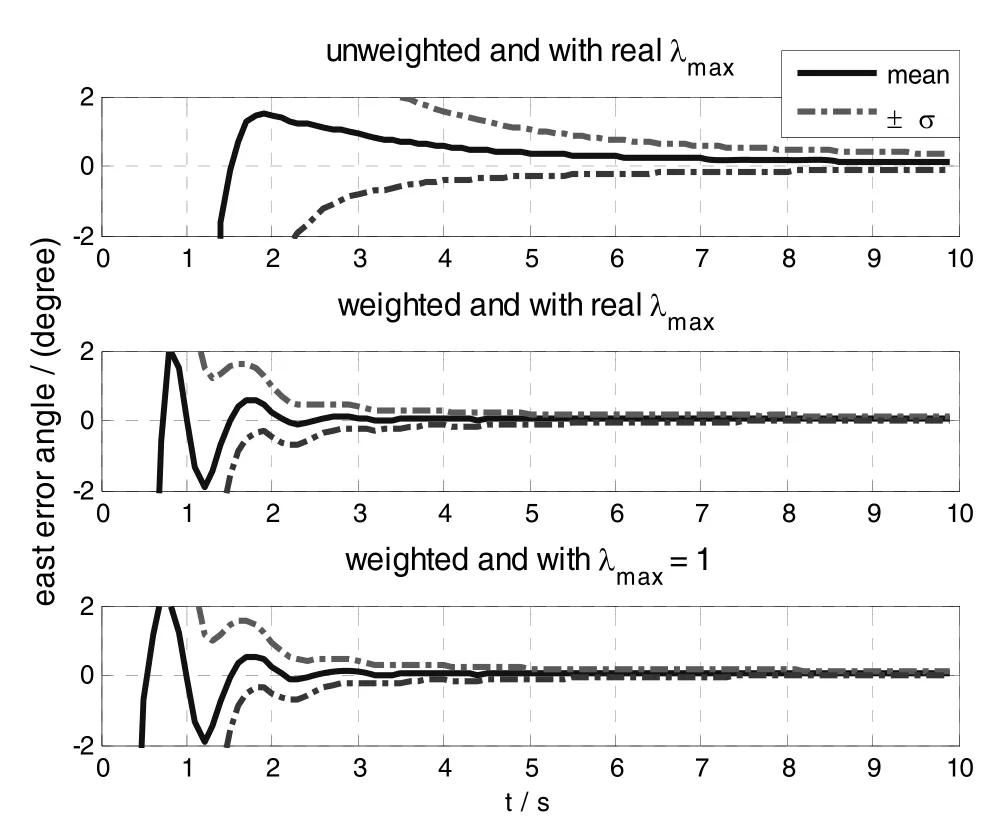
Fig.5 East error angle of the alignment algorithm
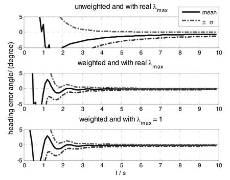
Fig.6 Heading error angle of the alignment algorithm
Comparing the result curves of the optimal weighted and unweighted alignment algorithms in Fig.4 ~ Fig.6,it is obvious that the optimal weighted alignment algorithm converges faster and achieves better results which are further listed in table.1.
Then comparing the result curves of the optimal weighted alignment algorithm using the realλmaxand the one using unity instead of the realλmaxin Fig.4 ~Fig.6,it is clearly showed that the two alignment schemes perform the same which is also verified by the results listed in table.1.
So,the Monte Carlo simulation results strongly validate the proposed in-flight alignment algorithm,the optimization and simplification techniques.
Due to the deterministic property,the algorithm will also be robust.Thus the proposed algorithm is a simple robust in-flight alignment method and will be very suitable for the real engineering applications.

Tab.1 The Monte Carlo simulation result of the proposed in-flight alignment algorithm
[1]Zhao Lin,Nie Qi,Gao Wei.A comparison of nonlinear filtering approaches for in-motion alignment of SINS[C]// Proceedings of IEEE International Conference on Mechatronics and Automation.Harbin,China,2007:1310-1315.
[2]Kim K,Park C G.Non-symmetric unscented transformation with application to in flight alignment[J].International Journal of Control,Automation,and Systems,2010,8(4):776-781.
[3]Hao Yan-ling,Xiong Zhi-lan,Hu Zai-gang.Particle filter for INS in-motion alignment[C]//Proceedings of IEEE Conference on Industrial Electronics and Application.Singapore,2006:9-13.
[4]Qin Yong-yuan,Yan Gong-min,Gu Dong-qing,et al.A clever way of SINS coarse alignment despite rocking ship[J].Journal of Northwestern Polytechnical University,2005,23(5):681-684.秦永元,严恭敏,顾冬晴,等.摇摆基座上基于信息的捷联惯导粗对准研究[J].西北工业大学学报,2005,23(5):681-684.
[5]Silson P M G.Coarse alignment of a ship’s strapdown inertial attitude reference system using velocity loci[J].IEEE Transactions on Instrumentation and Measurement,2011,60(6):1930-1941.
[6]Wu Yuan-xin,Pan Xian-fei.Velocity/position integration formula,Part Ⅰ:Application to in-flight coarse alignment[J].IEEE Transactions on Aerospace and Electronic Systems,2013,49(3):1006-1023.
[7]Wu Feng,Qin Yong-yuan,Cheng Yan.Transfer alignment for missile-borne SINS using airborne GPS on moving base[J].Journal of Chinese Inertial Technology,2013,21(1):56-60.吴枫,秦永元,成研.基于GPS的弹载捷联惯导动基座传递对准技术[J].中国惯性技术学报,2013, 21(1):56-60.
[8]Shuster M D,Oh S D.Three-axis attitude determina- tion from vector observations[J].Journal of Guidance and Control,1981,4(1):70-77.
[9]Cheng Y,Shuster M D.Robustness and accuracy of the Quest algorithm[C]//Proceedings of Advances in the Astronautical Sciences.Arizona,USA,2007:41-61.
[10]Shuster M D.Approximate algorithms for fast optimal attitude computation[C]//Proceedings of AIAA Guidance and Control Conference.California,USA,1978:88-95.
1005-6734(2014)01-0051-07
制导炮弹捷联惯导基于GPS的飞行中对准算法
梅春波,秦永元,游金川
(西北工业大学 自动化学院,西安 710129)
提出了一种适用于制导炮弹上低精度MEMS IMU/GPS组合系统的飞行中初始对准算法。通过引入辅助的载体惯性系和导航惯性系,将所求姿态四元数分解为三部分:第一部分描述载体系相对于载体惯性系的姿态,由MEMS陀螺仪输出积分求解;第二部分描述导航系相对于导航惯性系的姿态,利用GPS位置输出解析求解;第三部分描述两辅助惯性系的相对姿态,采用Re-quest算法完成解算。详细讨论了算法误差、有效性条件,并对Re-quest算法进行了优化和简化。蒙特卡洛仿真结果表明,在弹体加速度以指数规律变化条件下,对准算法可以在10 s时间内达到水平误差小于0.2°(1σ)、航向误差小于0.4°(1σ)的精度,完全满足制导炮弹组合系统初始对准的精度要求。
空中对准;MEMS IMU/GPS;Re-quest;误差分析;充分条件
U666.1
:A
2013-09-18;
:2013-12-23
总装备部惯性技术预研基金(51309040501)
梅春波(1985—),男,博士研究生,从事惯性导航对准算法研究。E-mail:chunbomei@gmail.com
联 系 人:秦永元(1946—),男,教授,博士生导师。E-mail:qinyongyuan@nwpu.edu.cn
10.13695/j.cnki.12-1222/o3.2014.01.011
