Initial alignment of SINS on revolving base for antenna tracking stabilized platform
2014-07-19ZHANGHuaqiangXUJingZHAOYan
ZHANG Hua-qiang,XU Jing,ZHAO Yan
(1.School of Mechanical Engineering,Shandong University of Technology,Zibo 255049,China;2.School of Materials Science and Engineering,Shandong University of Technology,Zibo 255049,China;3.Beijing University of Aeronautics and Astronautics,Beijing 100191,China)
Initial alignment of SINS on revolving base for antenna tracking stabilized platform
ZHANG Hua-qiang1,XU Jing2,ZHAO Yan3
(1.School of Mechanical Engineering,Shandong University of Technology,Zibo 255049,China;2.School of Materials Science and Engineering,Shandong University of Technology,Zibo 255049,China;3.Beijing University of Aeronautics and Astronautics,Beijing 100191,China)
In order to improve the initial alignment precision of strapdown inertial navigation system(SINS) and reduce the initial alignment time,an initial alignment scheme based on revolving base is put forward according to the antenna tracking stabilized platform structure.Then the initial alignment mathematical models based on revolving base are built.The singular value decomposition(SVD) method is used to analyze the observability of SINS initial alignment.The experimental results show that the revolving base alignment method can improve observability degree of SINS,which can significantly improve the alignment precision and reduce the initial alignment time compared with stationary base alignment method.
revolving base;initial alignment;SINS;SVD;observability analysis
The attitude change of mobile carrier affects the pointing of satellite communication antenna,keeping the antenna platform stability is key technology of eliminating this disturbance.And the core technology of stabilized platform is attitude measurement and control of mobile carrier.
The SINS can measure the acceleration of the mobile carrier,after the acceleration integral,the carrier’s velocity and position can be calculated,so the initial value of integral which includes initial velocity and initial position must be known[1].If SINS takes the geography frame as navigation frame,either physics platform or math platform is chosen as the measurement benchmark of acceleration,the platform must be tracedto the geography frame accurately in order to reduce the acceleration measurement error.The three axes’ point of platform is discretionary after the SINS start-up,so it is need to align the three axes’ point of platform before navigation,which is called SINS initial alignment.The SINS initial alignment precision can directly affect the navigation precision,besides the time of initial alignment is another key index of SINS.
The organization of this paper proceeds as follows.In the next section,the scheme and structure design of revolving base alignment will be introduced.In section 3,the mathematic analysis of SINS initial alignment based on revolving base will be performed,which include the error model of SINS,the state and measurement equation,the observability analysis based on SVD method.At the last section,the experiment and analysis are presented.
1 The Scheme and Structure Design of Revolving Base Alignment
1.1 The scheme of revolving base alignment
In Ref.[2],the navigation system state vector is totally observable in the two-position initial alignment by changing azimuth,and the initial alignment precision especially the azimuth estimation precision can be improved effectively.After analyzing pertinent references [1,3-6],it can be concluded that the estimation precision of system state vector can be improved by changing azimuth.But only a few angles are changed in SINS multi-position initial alignment,so if more angles are changed,the estimation precision will be further improved.
The revolution-modulation principle of SINS is simple,and the implementation method is various[4].In this paper,the SINS will be rotated as a whole system,which is called system revolution-modulation.This scheme can be implemented simply in engineering and the SINS sensors’ orthogonality can be ensured easily.
According to the stabilized platform structure of antenna,which can rotate around the azimuth axis,a new initial alignment method based on revolving base is put forward in this paper.The scheme can be described as follows:
The definition of various coordinate frames are given as[8]:sensor frame s,body frame b,navigation frame n,the revolving base rotates around axiszwith angle velocityω.So the transformation matrix between the sensor frame s and body frame b has the following form:

The gyro and the accelerometer errors on the sensor frame can be described as:

According to Eq.(1),the gyro and the accelerometer errors on body frame can be written as:

Eq.(4) and Eq.(5) are the SINS error modulation principle based on revolving base.When the antenna platform rotates aroundzaxis with angle velocityω,the inertial devices errors onxaxis andyaxis but notzaxis are modulated to trigonometric function.If the rotation time is (2π⁄ω),the integral result of scale coefficient errors,the installation errors and the biases are zeros,so this method can eliminate the non-random errors by integral[8],which can improve the initial alignment precision.
1.2 The structure and navigation algorithm of revolving base alignment
According to the tracking stabilized platform structure and working principle of antenna,the SINS can be fixed on antenna platform base as shown in Fig.1.

Fig.1 The structure of SINS initial alignment revolving base
The SINS can rotate aroundzaxis with the rotation of antenna platform base,so the method of initial alignment based on revolving base can be used here.
2 The mathematic analysis of SINS initial alignment based on revolving base
2.1 The error model of SINS
For the SINS initial alignment based on revolving base,the carrier is stationary,so the error equations of the initial alignment based on revolving base can be simplified as follows.
The misalignment angle equation can be described as:

The position error equation can be written as:

In order to define the relationship of inertial device random errors between navigation frame and sensor frame,the following relationship can be used:

2.2 The state and measurement equations
Generally,the first stage of SINS initial alignment is coarse alignment,which can be accomplished by least square method[9],all the state vector errors are very little after coarse alignment[10],so the SINS initial alignment error model can be considered as a liner model.
In order to shorten the alignment time and improve the filtering speed,the dimension of filter must be reduced.The position error can be ignored in the error model because the SINS position is known accurately when the SINS initial alignment.Because the SINS is not stable on vertical direction,so only the velocity error and accelerometer error on horizontal plane are used in SINS error model.The dimension of the SINS state vector can be reduced from fifteen to ten.In the navigation frame,the SINS initial alignment error model can be described as[11-14]:


During the initial alignment,two velocity errors δVEand δVNon horizontal plane are considered as measurements.So the measurement equation of SINS[13-15]can be expressed as:

2.3 The observability analysis of SINS initial alignment based on SVD method
The observability can reflect the estimate ability of the system state.The precision and efficiency of state estimation are affected by system observability degree[16].Eq.(11) and Eq.(13) can formulate the state equation and measurement equation of SINS initial alignment based on revolving base as follows:

The linear system can be seemed to stabilization system in limited time interval,which can be analyzed as piece wise constant system (PWCS)[3].If Stripped observability matrix (SOM) extracted from Total observability matrix (TOM) is used to analyze thesystem observability substituted the TOM,the analysis process will be simplified greatly[13].
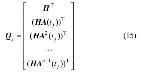
For the system of [A(t),H],the observability matrixQjofcan be described as:
采用SPSS 21.0统计学软件对本组研究对象的临床数据进行分析统计工作,以均数±标准差表示计量数据,以t检验;计数资料采用[n(%)]表示,采用卡方检验。若p<0.05,则表示组间数据对比差异显著,有统计学意义。

The TOMQ(j) and SOMcan be determined using the following equations:

Using SVD method[13],the matrixR(m×n) can be factorized as:

whereU=[u1,u2,…,um]andV=[v1,v2,…,vt]are unitary matrixes.,,is theith singular value.
The SVD method is more suitable for analyzing observability degree of PWCS,and the step can be described as follows:
1) Choosing the first timet1and calculatingA(t1),H1andQ1,according to the error characteristics and system measurement precision,Z1can be calculated.
2) Using the same method,QjandZjcan be calculated,and then the SOMof PWCS can be calculated,the single valuecan be calculated by SVD method.
3) Using Eq.(19),every element of state variableX0can be calculated corresponding every single value.The observability of every state vector component can be determined by element value ofX0.


3 Experimental results
3.1 Experimental conditions
In order to verify the performance of SINS initial alignment based on revolving base,some experiments have been performed.In order to simplify the experiment,the antenna base is replaced by turntable,the experimental parameters are given in Tab.1.

Tab.1 Experimental parameters
In Tab.1,ω-Rotation angle velocity of antenna base.r-The distance between SINS and antenna base center.
3.2 Experimental results and discussion
According to the Experimental parameters shown in Tab.1,the gyro data and accelerometer data of SINS initial alignment based on revolving base are illustratedin Fig.2 and Fig.3 respectively.
This paper analyzes the change of SOM minimal single value based on revolving base and stationary base respectively,the results of which are shown in Fig.4 and Fig.5 respectively.The SOM minimal single value based on revolving base increases continuously with the change of azimuth,which is about decuple of the minimal single value based on stationary base.Because the system observability degree is high when the single value is large,so the observability degree of SINS initial alignment based on revolving base is higher than the one based on stationary base.

Fig.1 Gyro data of SINS initial alignment based on revolving base

Fig.2 Accelerometer data of SINS initial alignment based on revolving base

Fig.4 The change of minimal single value based on revolving base

Fig.5 The change of minimal single value based on stationary base

Fig.6 The mean-squared error of azimuth estimation

Fig.7 The mean-squared error of roll estimation

Fig.8 The mean-squared error of pitch estimation

Tab.1 The alignment precision of azimuth

Tab.2 The alignment precision of roll

Tab.3 The alignment precision of pitch
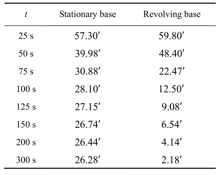
Fig.6 and Tab.2 show that the estimation precision of azimuth error based on stationary base is poor because of the low observability degree.The estimation azimuth is 28.10′ at 100 s and 26.74′ at 150 s,and then drives to stabilization after that.But the SINS initial alignment based on revolving base can get more information by changing the azimuth continuously,which can improve the observability degree of system state.The estimation azimuth is 12.50′ at 100 s,6.54′ at 150 s,4.14′ at 200 s and then drives to stabilization after that.
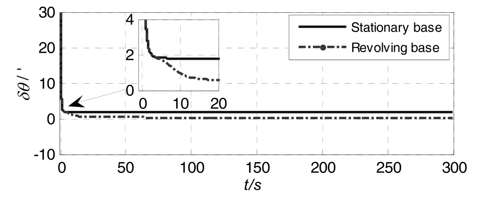
Fig.7~Fig.8 and Tab.3~Tab.4 show that the estimation precision of horizon attitude error based on stationary base is high,which can converge to less than2′.The horizon attitude error mainly relates to.Because the single value corresponding tobased on revolving base is high,so the estimation precision of horizon attitude error can converge to less than 40′.
4 Conclusion
This paper analyzed the structure of the antenna tracking stabilized platform firstly,then the initial alignment scheme of revolving base alignment is put forward,and the mathematical models of revolving base alignment are built and simulated.In order to analyze the observability of SINS revolving base alignment,the SVD method is used.at the end of the paper,the experimental results and analysis are given,which show that the SINS initial alignment precision can be improved evidently on revolving base,the estimation azimuth is 6.54′ at 150 s,4.14′ at 200 s and then drives to stabilization after that and the estimation precision of horizon attitude error can converge to less than 50′ in 20 s.
[1]Liu Xixiang,Xu Xiaosu,Wang Lihui.A fast compass alignment method for SINS based on saved data and repeated navigation solution[J].Measurement,2013,46(10):3836-3846.
[2]Yang Lijian,Yang Yang,Gao Songwei.Study on the low accuracy IMU′s initial alignment technique in the pipeline′s geographical coordinate measuring system[J].Procedia Engineering,2012,29:2644-2648.
[3]Qian Wei-xing,Zhu Xin-hua,Su Yan.A method improving the alignment accuracy of medium accuracy MEMS inertial navigation system on revolving base [C]//2010 International Conference on Mechatronics and Automation (ICMA).2010:809-812.
[4]Qian Weixing,Liu Jianye,Zhao Wei.Novel method of improving the alignment accuracy of SINS on revolving mounting base [J].Journal of Systems Engineering and Electronics.2009,20(5):1052-1057.
[5]Goshen-Meskin D,Bar-Itzhack I Y.Observability analysis of piece-wise constant systems-Part I[J].IEEE Trans.on Aerospace and Electronic Systems,1992,28(4):1056-1067.
[6]Goshen-Meskin D,Bar-Itzhack I Y.Observability analysis of piece-wise constant systems-Part Ⅱ [J].IEEE Trans.on Aerospace and Electronic Systems,1992,28(4):1068-1075.
[7]Feng Sun,Wei Sun.Mooring alignment for marine SINS using the digital filter[J].Measurement,2010,43(10):1489-1494.
[8]Zhang Ling,Liu Jianye,Lai Jizhou.Rotating fiber optic gyro strap-down inertial navigation system with three rotating axes[J].Transactions of Nanjing University of Aeronautics&Astronautices,2008,25(4):289-294.
[9]Gao Wei-Xi,Miao Ling-juan,Shen Jun.A new piece-wise fast alignment method for SINS stationary self-alignment [C]//Control Conference(CCC),2010 29th Chinese.2010:3307-3310.
[10]Gao Weixia,Miao Lingjuana,NI Maolinb.Multiple fading factors Kalman filter for SINS static alignment application[J].Chinese Journal of Aeronautics,2011,24:476-484.
[11]Wang Xin-long,Shen Gong-xun.A fast and accurate initial alignment method for strapdown inertial navigation system on stationary base[J].Journal of Control Theory and Applications,2006,3(2):145-149.
[12]Songyin Cao,Lei Guo.Multi-objective robust initial alignment algorithm for Inertial Navigation System with multiple disturbances [J].Aerospace Science and Technology.2012,21(1):1-6.
[13]Long Rui,Qin Yong-yuan,Jia Ji-chao.Observable Degree Analysis of SINS Initial Alignment Based on Singular Value Decomposition:IEEE International Symposium on Knowledge Acquisition and Modeling Workshop,2008.KAM Workshop 2008.[Z].2008.
[14]Ali J,Ushaq M.A consistent and robust Kalman filter design for in-motion alignment of inertial navigation system[J].Measurement,2009,42(4):577-582.
[15]Lu Shaolin,Xie Ling,Chen Jiabin.New techniques for initial alignment of strapdown inertial navigation system [J].Journal of the Franklin Institute,2009,346(10):1021-1037.
[16]Batista P,Silvestre C,Oliveira P.On the observability of linear motion quantities in navigation systems[J].Systems &Control Letters,2011,60(2):101-110.
1005-6734(2014)01-0032-06
一种用于天线跟踪稳定平台的SINS转动基座初始对准方法
张华强1,许 敬2,赵 剡3
(1.山东理工大学 机械工程学院,淄博 255049;2.山东理工大学 材料科学与工程学院,淄博 255049;3.北京航空航天大学 仪器科学与光电工程学院,北京 100191)
提出一种应用于天线跟踪稳定平台的捷联惯导转动基座初始对准方法。首先对卫星天线跟踪稳定平台的结构进行分析,得出在不改变系统现有硬件结构条件下,可充分利用天线跟踪稳定平台的结构特点进行转动基座初始对准的结论;建立完整的捷联惯导旋转基座初始对准数学模型,并采用奇异值分解法分析捷联惯导转动基座初始对准的可观测性。实验结果表明,该方法初始对准中系统可观测矩阵的最小奇异值比静基座初始对准可观测矩阵最小奇异值大一个多数量级,能提高捷联惯导系统的可观测性,并能有效地提高姿态角尤其是航向角的对准精度,为提高通信卫星天线跟踪稳定平台的性能提供了有价值的参考。
旋转基座;初始对准;捷联惯导;奇异值分解法;可观测性分析
U666.1
:A
2013-10-18;
:2014-01-02
国家自然科学基金(51105026)
张华强(1982—),男,博士,讲师,从事检测与导航技术研究。E-mail:huaqiang.zhang@163.com
10.13695/j.cnki.12-1222/o3.2014.01.008
