Growth of Hierarchically Structured High-Surface Area Alumina on FeCralloy®Rods
2014-07-12ChandniRallanArthurGarforth
Chandni Rallan,Arthur Garforth*
The University of Manchester,SCEAS,Manchester M13 9PL,UK
Growth of Hierarchically Structured High-Surface Area Alumina on FeCralloy®Rods
Chandni Rallan,Arthur Garforth*
The University of Manchester,SCEAS,Manchester M13 9PL,UK
A R T I C L E I N F o
Article history:
Received 24 December 2013
Received in revised form 19 February 2014
Accepted 9 April2014
Available online 19 June 2014
Foil
γ-Alumina
Catalytic support
Packed bed reactor
Metalsupport
The formation of metastable alumina phases due to the oxidation of commercial FeCralloy®rods(0.5 mm thickness)at various temperatures and time periods has been examined.This structured layer acts as an anchor to bind additional coatings of alumina via wash-coat techniques,thereby improving the layer thickness and increasing adhesion of the catalytic surface.Optimisation of the layer thickness and catalytic properties were conducted,using a range of analytical systems[scanning electron microscope(SEM),energy dispersive X-ray (EDX)and X-ray diffraction(XRD)].The modi fi ed FeCralloy®rods were tested in a fixed bed reactor rig to assess the impact on yield for the dehydrogenation of methylcyclohexane.
©2014 The Chemical Industry and Engineering Society of China,and Chemical Industry Press.Allrights reserved.
1.Introduction
Modern car-exhaust systems use catalysts supported on ceramic monoliths.The lastdecade has seen a move towards metallic monoliths affording improved conversion and selectivity[1].The use of catalysts supported on metal for packed bed catalytic reactions are limited[2]. A structured catalyst with an alumina wash coat deposited on a highly conductive support,such as a FeCralloy®,has the potentialto eliminate the heat transfer limitations in catalytic processes[1,3-5].An adherent alumina wash coat on metal supports remains a challenge both ensuring that the support is anchored when thermalcycling is inherent in the operation of fixed bed reactors and ensuring that sufficient active catalyst is available to maintain required conversions.
The growth of transient metastable alumina(θ-,γ-)on foils when oxidised at temperatures of 1073 K-1273 K for varied time periods has been reported[6-8].During the phase transformation of the transient alumina,there are particular oxidation parameters which result in the growth of aγ-Al2O3layer which has properties of high surface area and porosity.The structured morphology helps improve the adherence of a coating layer and also forms a base for synthesis of other supported catalysts[9].
Adhesion of coatings on non-porous structures such as FeCralloy®is non-trivial.Coating deposition is usually conducted by dip coating, spray coating or brush coating[9].Dip coating is by far the most common method due to its ability to produce uniform and repeatable results.There are also known correlations between the thickness of the layer,viscosity of the medium and withdrawal speed.The coatings can either incorporate the catalyst directly or act as a support upon which the catalytic phase may be deposited within.Meille and Pallier [2]achieved a very thin layer of alumina deposited on FeCralloy®fibres however,there were significant cracks observed even in such a thin layer.The coated fi bres were further impregnated with platinum;this step was not found to be detrimentalto the integrity of the coating.It was also found that the precursor to alumina to produce the sol should not be thermally pre-treated.From the observations it was proposed that thermal pre-treatment of the precursor eliminates hydroxyl groups,thus reducing the potential number of surface chemical bonds between the sol and support—the result being non-uniform nonadherent layers.The sol's viscosity was also found to play a crucial role in the thickness developed.The viscosity was controlled by changing the alumina concentration and pH of the sol.
This paper aims to give a better understanding of the growth of the γ-Al2O3layer by the controlled oxidation of FeCralloy®rods followed by a one-step hybrid deposition method.The prepared catalyst was loaded with 1%(by mass)platinum and its catalytic activity was assessed by testing it for dehydrogenation of methylcyclohexane.
2.Experimental
2.1.Material
FeCralloy®rods of thickness 0.5 mm with a chemicalcomposition (by mass)of72.8%Fe,22%Cr,5%Al,0.1%Y and 0.1%Si,were used.The wires were commercially manufactured and supplied by GoodFellow (UK).The rods were annealed in a continuous furnace at 1373 K prior to being supplied.
2.2.Method
2.2.1.Support oxidation
Prior to subjecting the samples to any oxidation,the surface of alloy rods was roughened to remove any oxide layer which may have formed during the annealing process.Also,previous work has shown that an increase in surface texture enhances the growth of the oxide layer [10].A three step chemicaltreatment described by Wu et al.[11]was carried out to remove any silicon deposits which mighthave occurred during sandpapering.The rods were fi rst subjected to an alkaliwash for 10 min followed by acid wash for the same time.The final step was an ultrasonic bath in acetone for 30 min followed by an ultrasonic bath in de-ionised water.These treated rods were calcined in a Thermo Gravimetric Anlyzer(TGA)at1073 K-1473 K for differenttime periods (0.5 h-16 h)under fl owing air(0.83 cm3·s-1),to obtain the optimum conditions which favour for the growth of a uniformγ-Al2O3layer on the surface.
2.2.2.Coating deposition
The oxidised rods(calcined at the optimum temperature)were loaded with multiple alumina washcoats through the method of dip coating.A one step deposition method as suggested by Liu et al.[12] was employed.To improve the adherence of the washcoatlayer,a binder sol was prepared which is added to the washcoat slurry to increase the loading.The binder solcomprised of4%(mass fraction)boehmite powder(DISPERAL®,supplied by Sasol)dispersed in 16%(mass fraction)conc.HNO3and 80%[the oxidised rods(calcined at the optimum temperature)]were loaded with multiple alumina washcoats through the method ofdip coating.A one step deposition method as suggested by Liu et al.[12]was employed.To improve the adherence of the washcoat layer,a binder sol was prepared which is added to the washcoat slurry to increase the loading.The binder solcomprised of 4%(mass fraction)boehmite powder(DISPERAL®,supplied by Sasol) dispersed in 16%(mass fraction)conc.HNO3and 80%(mass fraction) distilled water.The slurry was prepared by dispersing 23%of the binder sol prepared in 23%γ-Al2O3(PURALOX®,supplied by Sasol)powder and 54%(mass fraction)distilled water followed by vigorous stirring at 298 K for 24 h.The calcined FeCralloy rods were cut into strips of 2.5 cm and fitted onto PTFE blocks(Fig.1).These blocks were immersed into the prepared slurry and were withdrawn at a constant speed of 0.05 cm·s-1.The coated rods were fl ash dried at393 K prior to loading with two additional washcoats.The coated samples were calcined at 923 K for 2 h to reveala well adherent alumina layer.The totalmass of the alumina coating(on the coated rods tested in an experimental run)was found to be 0.1 g.

Fig.1.FeCralloy®rods washcoated with alumina layer.
2.3.Support characterisation
2.3.1.Surface morphology
The varied surface morphology of the oxidised wire samples was analysed using an environment alscanning electron microscope (Quanta 200 FEI).Each rod sample was examined using the ESEM under high vacuum conditions and coated with gold by the method of physical vapour deposition to enable improved image quality. Allsamples were analysed at an accelerated voltage of30.0 kV at magnifications ranging from 50 times to 25,000 times the originalsize.
2.3.2.Chemical analysis
Using an energy dispersive X-ray spectrometer(EDAX Genesis),an elemental analysis was done on the surface of the oxidised samples to obtain an indication of the varied surface composition.Multiple spots were analysed to ensure uniformity and also to obtain an average elemental composition.All the samples were embedded vertically in an electro-conductive resin,Demote 70™.The resin was then cut and polished to a 1μm finish.This standard technique was employed to establish the thickness of the oxide layer.This method ensures analysis being done on a fl at surface rather than a curved surface thus confirming that the EDX relative intensity signals are from the thin oxide layer and notthe underlying alloy substrate.Using a back scattering electron detectora line scan was done across the oxide layeraround the wire surface to estimate the thickness of the oxide layer.Samples were analysed at an accelerated voltage of30.0 kV under high vacuum conditions and chamber pressure of8.9×10-4Pa. 2.3.3.Phase analysis
Using the Philips X'Pert PRO,X-ray diffraction experiments were performed on the samples in the 2θrange of 0.52 rad-0.87 rad and a scanning speed of 2.618×10⁻⁶rad·s-1.Slit widths of 0.004 rad and 0.008 rad were used for all the experiments.A qualitative chemical phase analysis was performed on the oxide layer grown on the alloy rods.X'Pert Data viewer programme was used to analyse the results obtained from the XRD scan.
2.4.Catalytic testing
The alumina coated FeCralloy®rods were loaded with 1%(by mass) platinum by the method of wet impregnation.The Pt precursor was a 0.0001 mol·L-1hexachloroplatanic acid(H2PtCl6·6H2O).The coated rods were added to this solution and gently stirred 30 min at 305 K. This mixture was gently heated to 343 K and constantly stirred for 2 h and then heated up to 393 Kand left to dry overnight.The rods were tested for dehydrogenation of methylcyclohexane(MCH)in the experimentalset up shown in Fig.2.The design specifications of reactor used for dehydrogenation are listed in Table 1.The activity of the structured catalyst was tested under a range of operating conditions as described in Table 2.
The prepared structured catalystrods were loaded uniformly into the middle zone(L=0.05 m)of the reactor(ID=0.011 m)and the top zone (L=0.2 m)was packed with carborundum(d=0.1 mm)to actas a feed pre-heater and distributor.Part of the bottom zone of the reactor was filled with carborundum and was connected to the separation unit of the experimentalrig external to the furnace.The three zones in the reactor were separated with quartz wool to prevent the catalyst from moving into the voids between the carborundum.The totallength of the catalyst bed was 5 cm and the total mass of the catalyst bed was 9.54 g.
Prior to catalysis,the rods were activated by the method of calcination and reduction which were done in-situ.The catalyst was calcined at773 K for 6 h under fl owing air(0.83 cm3·s-1)and reduced at723 K for 16 h in H2(0.83 cm3·s-1).To obtain a detailed quantitative assessment of the selectivity towards the formation of toluene atvarious operating conditions, allsamples were analysed in a GC-MS(Agilent Technologies,Model-6890 N)equipped with a HP-5MS capillary column(50 m×0.00025m i.d.,5%phenyl and 95%methyl polysiloxane).Samples were prepared by dilution in dichloromethane(AR)for the GC-MS to quantify the reactant conversions and product yields.Standard mixtures of key products(0.005%-0.1%,by volume)such as methylcyclopentane,heptane,methylcyclohexene benzene,xylene(o-,p-)and biphenyl were also made up in dicholoromethane.
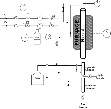
Fig.2.Catalytic rig for catalytic dehydrogenation of methylcyclohexane.H2—Hydrogen; CA—compressed air;CK—check valve;PI—pressure indicator;TI—temperature indicator;WI—mass indicator;TC—temperature controller;FC—fl ow controller.
3.Results and Discussion
3.1.Oxidation of FeCralloy®rods
Oxidation of FeCralloy®at high temperatures results in the growth of an alumina rich layer.Previous authors have proven that different phases ofalumina exhibit different growth mechanisms,transient alumina tends to grow by an outward diffusion mechanism andα-Al2O3grows by inward diffusion[13].During the initialstage of oxidation, Fe and Cr ions tend to get preferentially oxidised due to their increased concentration.However,Alhas a higher affinity for O when compared to Fe and Cr ions,and thus gets preferentially oxidised with the passage of time to result in an alumina layer[14].The Cr2O3that is initially formed acts as nucleation centres for Al2O3[15].Hence with increasing time as the thickness of the alumina layer increases,there appears to be decreasing concentrations of Fe and Cr.The outward diffusion of Aland inward diffusion of O result in an outward growth of a transient alumina rich layer on the surface of the rod.

Table 2 Range of operating conditions for dehydrogenation of MCH
3.2.ESEM characterisation
The ESEM was used to analyse the varied morphology of the FeCralloy®samples at different stages of oxidation.Fig.3(a)shows the image of the rod prior to being subjected to any surface rougheningand Fig.3(b)shows the surface once the samples have been sandpapered and the difference in surface roughness is apparent.

Fig.3.Varied morphology of the FeCralloy®samples at different stages ofoxidation.

Fig.4.Comparison of the surface structure postisother maloxidation for 16 h at different temperatures in the range of 1073 K-1473 K.
ESEMimages of the oxidised rod at1073 K[Fig.3(c)]revealed a morphology which was very similar to the rod surface prior to any oxidation treatment[Fig.3(b)].Acomparison of the surface structure postisothermal oxidation for 16 h at different temperatures in the range of1073 K-1473 K has been shown in Fig.4.
The surface appears to be smooth when oxidised at 1073 K but with increasing temperature a platelet formation can be seen which at higher temperatures(1373 K)begins to sinter.At 1173 K short alumina oxide platelets appear to be forming on the surface, which at 1273 K appear to have transformed into a dense growth of platelets.Following the temperature test,a time optimization study was carried out again using the TGA.Samples were isothermally oxidised at 1273 K for varying time periods between 0.5 h and 16 h.
Fig.5 shows the varied morphology at the different sampling times.Although a platelet-like morphology can be seen forming on the surface(as early as 0.5 h),they are short and fl at during the initialstages of thermaloxidation.With increasing time these platelets appear to transform intoα-Al2O3morphology,which form nucleation centres for further densi fi cation and growth of new platelets. Finally by 16 h these platelets sinter and produce a more condensed phase.
The alloy surface shown in Fig.6 has long randomly oriented whiskers formed on the surface after 8 h of isothermaloxidation at 1273 K. Isothermal oxidation at 1273 K for varied time periods resulted in a dense growth of platelets formed across the surface of the wire.For shorter periods of time,oxidation at 1273 K resulted in the growth of an oxide scale but ESEManalysis revealed the morphology to be more fl at which would not be suitable if a was hcoat layer is to be applied. With increasing time the growth of the blade-like structure was more uniform across the entire surface.Previous authors described this morphology to be that of transient alumina[7,16].EDX and BSE characterisation showed that with time the alumina concentration increased on the surface.
Increased time of exposure or very high temperature oxidation results in sintering of the oxide scale again,rendering alloy unsuitable to be used catalytically[17,18].Work in the past suggests that the most suitable morphology on the alloy surface for use as a catalytic support is the growth of randomly oriented whiskers[17].In this study(Fig.6),at a time period of 8 h,an even and well adhered layer ofγ-Al2O3seems to be formed on the surface.This layer has a thickness of around 4-5μm and a whisker-like morphology and subsequently a high surface area.
ESEM images also illustrate a phase transformation taking place on the surface of the alloy wires.At 1373 K there appears to be a wrinkling affect on the surface of the wire and the phase of alumina oxide present is predominantlyα-Al2O3[8].Exposure to high temperature oxidation for a very long time results in a depletion of the Alreservoir,which further results in breakaway oxidation of Fe and Cr,leading to a thick mixed oxide layer and also increased strain in the oxide layer[19,20].This causes an increased compressive stress in the oxide layer due to lateral growth strains,resulting in fragments of the layer being ejected from the surface as can be seen from the ESEMimage[Fig.4(c)].
A section of oxide growth on the alloy rod is shown in Fig.7.The dense growth of platelets can be seen and also an indication of a phase transformation of the oxide layer is obtained from the image.It is only at increased magnifications of6000×-50000×that the varied surface morphology can be seen.At lower magnifications the surface appears to be smooth with no distinct features.

Fig.5.The varied morphology at the different sampling times.
3.3.EDX characterisation
X-ray analysis was performed on the surface of the oxidised rods to obtain an elemental composition.The samples were embedded in a resin and allanalysis was carried out on a fl at surface.
Table 3 shows that the Al content increases with increase in temperature,resulting in an increase of the Al/Fe ratio.
Table 4 illustrates the varied elemental composition on the surface of the FeCralloy®rods when iso-thermally oxidised at 1273 K for varying sampling times,where concentration of Fe and Cr decreases with time.Initially there is a rapid increase in content of Alwhich stabilises with time.Using the EDX line scan programme in the EDAX GENESIS software package,the thickness of the oxide layer could be calculated as tabulated in Table 5.
From the line scan data it appears that the oxide layer that is formed is an alumina rich coating.Owing to the increased heatintensity of the process,breakaway oxidation of Cr and Fe initiates,resulting in a mixed oxide layer.The increased presence of Cr and Fe oxides could be detrimentalif the alloy rods are to be used as catalytic supports for certain catalytic applications.
Fig.8 describes the nature of the oxide layer formed on the underlying alloy after 0.5 h,2 h and 8 h of isothermaloxidation at 1273 K.Based on data obtained from the line-scan analysis and EDX data obtained from the different spots across the oxide layer,the thickness of the alumina layer and the mixed oxide layer formed on the alloy surface was determined.The alumina layer was de fi ned as less than 5%of the relative signalintensity of Fe and Cr as obtained from the line-scan data.
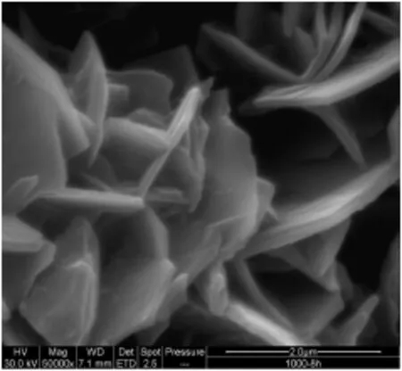
Fig.6.FeCralloy®after isothermaloxidation at 1273 K for 8 h.
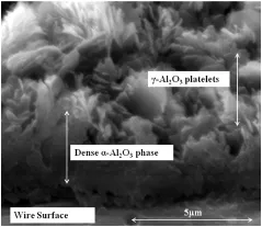
Fig.7.Varied morphology of FeCralloy®after isothermaloxidation at 1273 K for 16 h.

Table 5 EDX line scan data when samples isothermally oxidised at 1273 K for 0.5 h-8 h

Fig.8.The nature of the oxide layer formed on the underlying alloy after 0.5 h,2 h and 8 h of isothermal oxidation at 1273 K.
3.4.XRD characterisation
Fig.9 shows the varying intensity of the peaks when samples were oxidised isothermally for 16 h between 1073 K and 1473 K.Fig.10describes the varying intensity of the peaks when samples were oxidised isothermally at 1273 K for 1 h-16 h.

Table 4 EDX data when samples isothermally oxidised at 1273 K for 0.5 h-8 h

Fig.9.X-ray diffraction patterns for samples isothermally oxidised for 16 h at 1073 K-1473 K.
With increasing time and temperature the peaks appear to be getting sharper,indicating an increase in crystallite size and hence a decrease in surface area.XRD data con fi rms the presence of transition alumina on the surface of the rods.With increasing temperature and time periods the peaks obtained appeared to be getting sharper indicating a phase transformation to a more crystalline lower surface areaα-Al2O3.Analysing rod samples by XRD is more complex than powder samples.To avoid any ambiguity in the results,the Bragg-maxima have been shown in terms of interplanar distances.The results obtained are summarised in Table 6. Strong maxima were detected when the samples were oxidised at 1273 K-1473 K and for increased time of exposure as shown in Figs.9-10.
On-going in-situ XRD studies at the University of Manchester have revealed strong maxima for transient alumina when samples are oxidised at 1173 K after a prolonged period of oxidation.XRD data con firms the presence of transition alumina and also shows the change in crystallinity of the oxide layer with time and temperature.Data obtained was compared to the work done in the past and the result was expressed in terms ofinter-planar distances[13,21].The maxima for transition alumina were very strong for samples oxidised at 1273 K for 8 h.
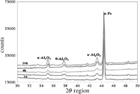
Fig.10.X-ray diffraction patterns for samples isothermally oxidised at 1273 K for 0.5 h-16 h.
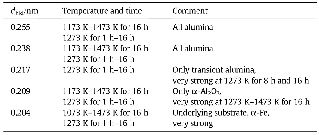
Table 6 Inter-planar distances of FeCralloy®isothermally oxidised at 1073 K-1473 K for 0.5 h-16 h
3.5.Characterisation of washcoated FeCralloy®rods
ESEManalysis of the coated rods revealed a smooth well adherent alumina coating(Fig.11).The rods were embedded in the Demote™resin and it was possible to obtain the thickness of the oxide layer, which was found to be 6μm(Fig.12).The integrity of the attached alumina to the oxidised FeCralloy®rod was tested by thermalcycling. This was done using a TGA and heating the rods from ambient to 773 K at 4.71 K·s-1under fl owing air,up to 5 times.There was no loss of weight during thermalcycling,indicating that theγ-alumina coatingand the sub-structured layer grown on the alloy surface had a matching crystallite grain structure.
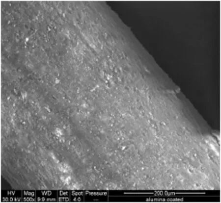
Fig.11.FeCralloy®rod washcoated with alumina layer.

Fig.12.Cross-section of FeCralloy®rod washcoated with alumina layer.

Fig.13.Time-on-stream(TOS)deactivation test,T=673 K,P=100 kPa,H2/MCH=9, VMCH=3 cm3·h-1.
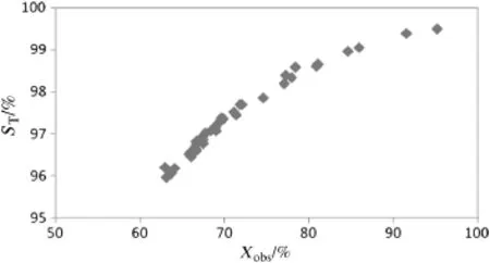
Fig.14.Selectivity(ST)decreasing with conversion,T=673 K,P=100 kPa,H2/MCH=9, VMCH=3 cm3·h-1.
3.6.Catalytic activity
Fecralloy rods,prior to washcoating,were calcined in a large tube furnace under fl owing air.This step required a scale-up of the oxidation process from the TGA(70 mg sample to 10 g).The optimum scale-up conditions,which resulted in a surface morphology obtained by oxidation at 1273 K for 8 h in the TGA,were found to be 1223 K for 10 h. The rods were loaded with the alumina washcoats via dipcoating and 1%(by mass)Pt through wet impregnation.High conversions(50%-99%)of MCH and increased selectivity(>98%)towards the formation of toluene were achieved at 613 K-673 K.Owing to the endothermic nature of the reaction there was a temperature drop of 10 K-15 K at all reaction temperatures.The catalytic activity of pelleted 1%(by mass)Pt/Al2O3catalyst[22]and the structured catalyst prepared by the authors were similar,however,the use of the pelleted catalyst at the same reaction conditions resulted in a temperature drop typically of 30 K-70 K[22].
Long term life tests have been performed to gauge the stability of the prepared catalyst and to build the deactivation into the kinetic model for the system.Fig.13 describes the observed conversion(Xobs)over a time period of480 h.During the initialstages of the deactivation tests there appeared to be a sharp drop in conversion(Fig.14).This could be attributed to the deactivation of the more acidic sites.After a time period of100 h the conversion stabilised.The alumina coating appeared to be adherent post catalytic testing,with a weight loss of0.8%.
4.Conclusions
This work has shown the varied morphology of Al2O3oxide layers grown on the surface of FeCralloy®wire at temperatures of 1073 K-1473 K.The growth ofγ-Al2O3after 8 h at 1273 K has been observed and the phase transformation fromγ-Al2O3toα-Al2O3was also noted. The high activity of the catalyst was comparable to the catalyst powder used fora similarexperiment.The developed supported catalyst proves to be highly beneficial where improved heattransfer across the catalytic bed is required,to avoiding the formation ofhotor cold spots and thus improving the conversion and kinetic interpretation.
Acknowledgements
The authors would like acknowledge Dr.Chris Muryn and Dr.Robin Pritchard,School of Chemistry,University of Manchester,for their help and guidance in the XRD analysis and Dr.Patrick Hill for assisting in all the SEM analyses and in preparing the resin samples.We would also like to express our gratitude to Sasolfor supplying the necessary chemicals,DISPERAL®and PURALOX®.
[1]P.Avila,M.Montes,E.E.Miró,Monolithic reactors for environmental applications:a review on preparation technologies,Chem.Eng.J.109(2005)11-36.
[2]V.Meille,S.Pallier,G.V.Santa Cruz Bustmanthe,R.Roumanie,J.P.Reymon,Deposition ofγ-Al2O3layers on structured supports for the design of new catalytic reactors, Appl.Catal.A Gen.286(2)(2005)232-238.
[3]J.L.Williams,Monolith structures,materials,properties and uses,Catal.Today 69 (2001)3-9.
[4]R.M.Heck,S.Gulati,R.J.Farrauto,The application of monoliths for gas phase catalytic reactions,Chem.Eng.J.82(2001)149-156.
[5]A.Bialas,W.Osuch,W.Lasocha,M.Najbar,The in fl uence of the Cr-Alfoiltexture on morphology of adhesive Al2O3layers in monolithic environmental catalysts,Catal. Today 137(2008)489-492.
[6]F.Liu,H.Gotlind,J.E.Svensson,L.G.Johansson,H.Halvarsson,Early stages of the oxidation of a FeCrAlRE alloy(Kanthal AF)at 900°C:A detailed microstructural investigation,Corros.Sci.50(2008)2272-2281.
[7]H.E.Kadiri,R.Molins,Y.Bienvenu,M.F.Horstemeyer,Abnormalhigh growth rates of metastable aluminas on FeCrAlalloys,Oxid.Met.64(2005)63-97.
[8]J.Jedlinski,The oxidation behaviour of FeCrAl‘alumina forming’alloys at high temperatures,Solid State Ionics 101-103(Part 2)(1997)1033-1040.
[9]V.Meille,Review on methods to depositcatalysts on structured surfaces,Appl.Catal. A Gen.315(2006)1-17.
[10]D.Zhang,L.Zhang,B.Liang,Y.Li,Effect of acid treatment on the high-temperature surface oxidation behavior of FeCrAlloy foilused for methane combustion catalyst support,Ind.Eng.Chem.Res.48(2009)5117-5122.
[11]X.Wu,D.Weng,L.Xu,H.Li,Structure and performance ofγ-alumina washcoat deposited by plasma spraying,Surf.Coat.Technol.145(2001)226-232.
[12]D.-J.Liu,D.R.Winstead,van den BusscheN.Method of preparing a catalyst layer over a metallic surface of a recuperator,US Pat.6540843(2003).
[13]J.Jedlinski,G.S.Kowalski,A.Bernasik,M.Nocun,J.Camra,The mechanism of early oxidation stages of Fe20Cr5Al-type alloys at 1123 K,Mater.High.Temp.26(2009) 259-272.
[14]E.Airiskallio,E.Nurmi,M.H.Heinonen,I.J.Vayrynen,K.Kokko,M.Ropo,M.P.J. Punkkinen,H.Pitkanen,M.Alatalo,J.Kollar,Third element effect in the surface zone of Fe-Cr-Alalloys,Phys.Rev.B 81(2010)033105-033109.
[15]H.Asteman,M.Spiegel,A comparison of the oxidation behaviours of Al2O3formers and Cr2O3formers at 700°C—Oxide solid solutions acting as a template for nucleation,Corros.Sci.50(2008)1734-1743.
[16]C.Badini,F.Laurella,Oxidation of FeCrAlalloy:influence of temperature and atmosphere on scale growth rate and mechanism,Surf.Coat.Technol.135(2001) 291-298.
[17]L.R.Chapman,C.W.Vigor,J.F.Watton,Enhanced oxide whisker growth on peeled Al/ containing stainless steelfoil,US Pat.4331631(1982).
[18]D.R.Sigler,G.L.Vanerman,Accelerated whisker growth on iron-chromium-aluminium alloy foil,US Pat.4915751(1990).
[19]C.Mennicke,D.R.Clarke,M.Rühle,Stress relaxation in thermally grown alumina scales on heating and cooling FeCrAl and FeCrAlY alloys,Oxid.Met.55(2001) 551-569.
[20]D.R.Clarke,Stress generation during high-temperature oxidation of metallic alloys, Curr.Opin.Solid State Mech.6(2002)237-244.
[21]R.Chegroune,E.Salhi,A.Crisci,Y.Wouters,G.Galerie,On the competitive growth of alpha and transient aluminas during the fi rst stages of thermaloxidation of FeCrAl alloys at intermediate temperatures,Oxid.Met.70(2008)331-337.
[22]F.AlHumaidan,D.Tsakiris,D.Cresswell,A.Garforth,Hydrogen storage in liquid organic hydride:selectivity ofMCH dehydrogenation over monometallic and bimetallic Pt catalysts,Int.J.Hydrogen Energy 38(2013)14010-14026.
*Corresponding author.
E-mailaddress:a.garforth@manchester.ac.uk(A.Garforth).
杂志排行
Chinese Journal of Chemical Engineering的其它文章
- Separation Science and Engineering Performance Prediction of Structured Packing Column for Cryogenic Air Separation with Hybrid Model☆
- Enhanced Photocatalytic Properties of Silver Oxide Loaded Bismuth Vanadate☆
- Recovery and Recycling of Ti Supported Bimodal Mesoporous Catalysts Prepared via Ship-in-a-bottle Method in the Epoxidation of Cyclohexene☆
- Promoting Xylene Production in Benzene Methylation using Hierarchically Porous ZSM-5 Derived from a Modified Dry-gel Route☆
- Energy,Resources and Environmental Technology Experimental and Modeling Study on de-NOxCharacteristics of Selective Non-catalytic Reduction in O2/CO2Atmosphere☆
- Energy,Resources and Environmental Technology CO2Removal from Biogas by Water Washing System☆
