Performance of the bio-inspired leading edge protuberances on a static wing and a pitching wing*
2014-06-01WANGYayun王雅赟
WANG Ya-yun (王雅赟)
Department of Engineering Mechanics, Shanghai Jiao Tong University, Shanghai 200240, China,
E-mail: wangyayun1990@gmail.com
HU Wen-rong (胡文蓉)
MOE Key Laboratory of Hydrodynamics, Shanghai Jiao Tong University, Shanghai 200240, China
Shanghai Jiao Tong University and Chiba University International Cooperative Research Center (SJTC-CUICRC), Shanghai Jiao Tong University, Shanghai 200240, China
Department of Engineering Mechanics, Shanghai Jiao Tong University, Shanghai 200240, China
ZHANG Shi-dong (张仕栋)
Shanghai Jiao Tong University and Chiba University International Cooperative Research Center (SJTC-CUICRC), Shanghai Jiao Tong University, Shanghai 200240, China
Department of Engineering Mechanics, Shanghai Jiao Tong University, Shanghai 200240, China
Performance of the bio-inspired leading edge protuberances on a static wing and a pitching wing*
WANG Ya-yun (王雅赟)
Department of Engineering Mechanics, Shanghai Jiao Tong University, Shanghai 200240, China,
E-mail: wangyayun1990@gmail.com
HU Wen-rong (胡文蓉)
MOE Key Laboratory of Hydrodynamics, Shanghai Jiao Tong University, Shanghai 200240, China
Shanghai Jiao Tong University and Chiba University International Cooperative Research Center (SJTC-CUICRC), Shanghai Jiao Tong University, Shanghai 200240, China
Department of Engineering Mechanics, Shanghai Jiao Tong University, Shanghai 200240, China
ZHANG Shi-dong (张仕栋)
Shanghai Jiao Tong University and Chiba University International Cooperative Research Center (SJTC-CUICRC), Shanghai Jiao Tong University, Shanghai 200240, China
Department of Engineering Mechanics, Shanghai Jiao Tong University, Shanghai 200240, China
(Received October 22, 2013, Revised December 27, 2013)
It is shown that the leading edge protuberances on the flippers of a humpback whale can significantly improve the hydrodynamic performance. The present study numerically investigates the flow control mechanisms of the leading edge protuberances on a static wing and a pitching wing. For static wings, the performance in both laminar flow and turbulent flow are studied in the context of the flow control mechanisms. It is shown that the protuberances have slight effects on the performance of static wings in laminar flow. Also, it could be deduced that non-uniform downwash does not delay the stall occurrence in either laminar flow or turbulent flow. In turbulent flow, the leading edge protuberances act in a manner similar to vortex generators, enhancing the momentum exchange within the boundary layer. Streamwise vortices do contribute to the delay of the stall occurrence. The normal vorticity component also plays an important role in delaying the stall occurrence. However, for the pitching wing, the effect of leading edge protuberances is negligible in turbulent flow. Detailed analysis of the flow field indicates that for the wing with the leading edge protuberances, the leading edge vortices become more complex, while the thrust jet and the vortices in the wake are not changed significantly by the leading edge protuberances.
leading edge protuberance, turbulent flow, laminar flow, a pitching wing, a static wing
Introduction
The humpback whale is an extremely large animal living in the ocean. However, it is quite maneuverable especially during its pursuit of prey. The agility of the humpback whale is believed to be attributed to the leading edge protuberances of its pectoral flippers. The effects of the protuberances on the performance of humpback whale flippers were widely studied experimentally and numerically.
Watts and Fish[1]found that the leading edge protuberances could enhance the wing performance, increasing 4.8% in the lift and 17.6% in the lift to drag ratio at an angle of attack of 10oaccording to the panel method simulation. Later, the wind tunnel measurements[2]show that the protuberances delays the stall angle by approximately 40%, while increasing the lift and decreasing the drag. The extending of the stall point by leading edge protuberances may find applications in engineering lifting surfaces. However,the flow control mechanism of the leading edge protuberances remains an issue to be studied.
Three main possible fluid dynamic mechanisms for improved performance were proposed. The first one is that the protuberances act as vortex generators. The large streamwise vortices in the regions posterior to the troughs between protuberances enhance the momentum exchange within the turbulent boundary layer. The second mechanism concerns the non-uniform downwash. The non-uniform downwash component caused by the streamwise vortices can reduce the effective angle of attack and delay the global stall. The last mechanism concerns the reduction of both spanwise flow and strength of the tip vortices.
Many studies support the first mechanism. It is argued that the delay of stall is due to the generation of streamwise vortices and the modification of the boundary layer. The variation of the leading edge sweep angle created by the leading edge protuberances introduces spanwise flow along the leading edge in the form of streamwise vortices. These vortices would create a low pressure region on the upper surface of the wing and are responsible for the improved lift[3]. Miklosovic et al.[2]regarded the leading edge protuberances as vortex generators, which could cause a greater momentum exchange within the boundary layer and thus help keep the flow attached to the lifting surface despite an adverse pressure gradient.
The second mechanism denies the vortex generator concept. Van Nierop et al.[4]argued that it is not possible for the protuberances to act as vortex generators, since the wavelength and the amplitude of the protuberances are much larger than the boundarylayer thickness. It was suggested that the high pressure gradient in a trough causes a separation to be initialized in this region. Furthermore, a non-uniform downwash component caused by the streamwise vortices leads to a reduced effective angle of attack. Thus the global stall is delayed.
Studies of a three-dimensional idealized flipper model provided some insight into the effect of the leading edge protuberances on the spanwise flow and the tip vortices. It is shown that the protuberances could maintain a chordwise flow, reducing the induced drag due to tip vortices. The leading edge protuberances generate streamwise vortices which could confine the leading edge separation to the tip region[5]. This mechanism is further supported by the experiments of Miklosovic et al.[2].
The Reynolds number in most studies of leading edge protuberances is about half a million. Little work has been conducted in laminar flow. Recently, Favier et al.[6]performed a direct numerical simulation on the wings atRe=800 and an attack of angle of o 20. It is found that both the lift and the drag of the wing with protuberances in the leading edge are lower than those of the wing with a smooth leading edge. It is suggested that the leading edge waviness changes the shape of the recirculation region and the flow is partially attached.
Above all, the flow control mechanism of the leading-edge protuberances is still unclear. One of the purposes of this paper is to discuss the first two mechanisms mentioned above. If the second mechanism is reasonable, the non-uniform downwash should also exist in laminar flow. Therefore, in this study, we investigate the performance of leading-edge protuberances in both laminar flow and turbulent flow to better understand the passive flow control mechanism.
On the other hand, fish and other aquatic animals can achieve greater maneuverability and higher efficiency than man-made marine vehicles by undulating their control surfaces. Hence, the active and passive flow control mechanism of the flapping wing is also an important research topic. A great effort was devoted to the study of active flow control of oscillating foils to identify kinematic parameters for optimal propulsive performances[7-12]. However, less attention was paid to the passive flow control of the oscillation wing. Stanway[13]performed an experimental study of flapping wings with and without leading edge protuberances in turbulent flow. It was found that with the same amount of energy consumed, the wing with leading edge protuberances gained lower efficiency and thrust. However, they did not show the detailed information about the flow field in their experiments. They suggested that the vorticity of the reverse Kármán vortex street is weakened by the interference of the vortex structures produced by the leading edge protuberances.
The aim of this paper is to study the mechanisms of the leading edge protuberances on the static wing and also the pitching wing. It is worth noticing that Reynolds number in almost all studies of leading edge protuberances is in the range of 5×10⁴- 5×10⁵, and the thickness of the foil is around 21% of the foil chord length. In fact, the actual Reynolds number is 106for the usual humpback[1]. In addition, it was found that thinner foils operating at higher Re are more likely to experience an increased maximum lift[13,14]. In order to achieve better performance, the section of NACA0010 airfoil is chosen at Reynolds number of 106in the present study.
1. Mathematical models and numerical methodology
1.1Geometry and mesh
Four ideal models of infinite span wings are simulated in this study. The baseline model has a smoo-th leading edge whereas the modified models have a sinusoidal leading edge. The wavy amplitude is 5% of the chord length,. And the wavelength is 25% of the chord length. The cross sections of the models are based on a NACA0010 airfoil. The grids for four models are shown in Fig.1. Only one wavelength in the spanwise direction of the modified wing is considered, as periodic boundary conditions are employed to simulate the infinite span wing.
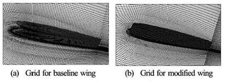
Fig.1 Grids for models
1.2 Numerical method
Numerical simulations are conducted by using the Fluent software. Both laminar flow and turbulent flow are simulated in this study. No-slip boundary conditions are used on the solid boundary. For the outlet, the gradients of flow parameters in the normal direction to the boundary are set to be zero.
For laminar flow, the Reynolds number is 1 000 (Re = Uc/μ, where U is the fluid velocity, c is the foil chord length, and μ is the kinematic viscosity of water). Incompressible Navier-Stokes equations are solved, with the second order upwind scheme is used in the spatial discretization and the PISO algorithm, and the time integration performed with an implicit second order scheme.
It is shown that the turbulent flow can be considered as fully developed for the flow over a wavy wing at the Reynolds number of 106[15]. The unsteady Reynolds Average Navier-Stokes equations are solved with the k-ω SST turbulent model, which is suitable for the problems with adverse gradient and separation. Wall functions are used near the wall and thus y+= 50 there.

Fig.2 Lift coefficient for static NACA 0012 foil at Re=106
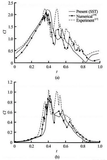
Fig.3 Time-dependent lift and drag coefficients for pitching NACA0012 foil at Re=106
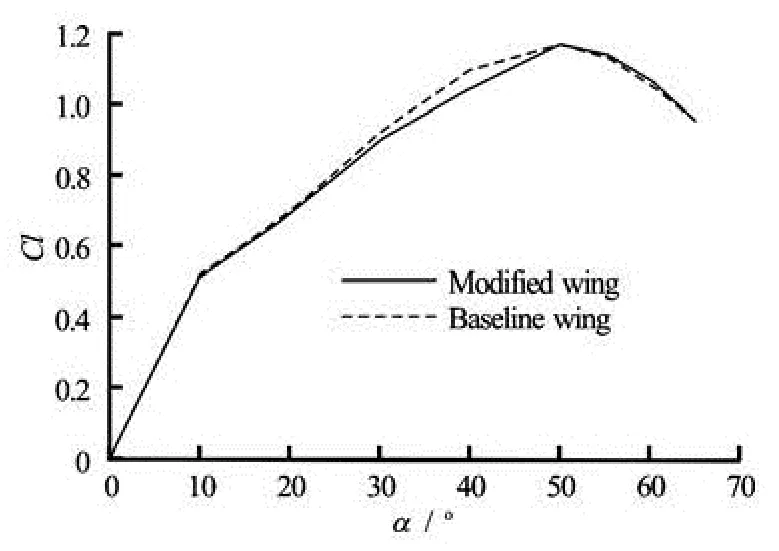
Fig.4 Lift coefficients at different angles of attack at Re=103

Fig.5 Vorticity for the modified wing at the attack angle of 10oand Re=103
1.3 Pitching motion of the NACA0010 wing
The pitching oscillation is described by
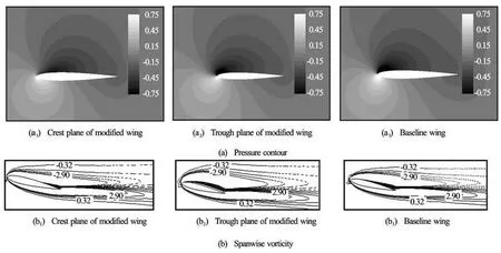
Fig.6 Pressure contours and spanwise vorticity contours for modified wing and baseline wing at angle of attack of 10oand Re=103

wheremα and f are the non-dimensional pitching amplitude and frequency, respectively.
The force coefficients are defined as
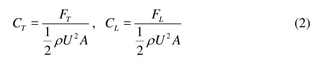
where FTand FLare the thrust and the lift force, respectively. A represents the projected plan-form area.
2. Numerical validation
For the numerical validation, a static and a pitching NACA0012 airfoil in turbulent flow are considered.
2.1 Validation tests for static foil
To test the present method in turbulent flow, the flow over a stationary NACA0012 airfoil is simulated at Reynolds number of 106. The results are compared with the experiments from Sheldahl and Klimas[16](Fig.2). It is shown that present simulation is in a good agreement with the experimental results.
2.2Validation tests for oscillating foils
A pitching NACA0012 airfoil is simulated at Re =106. The mean attack angle is 15° and the pitching amplitude is 10°. The present results are compared with the experimental results of McAlister et al.[17]and computational results of Martinat et al.[18]. Figure 3 shows that the numerical methods employed here are reliable for simulating oscillating foils at high Reynolds number.
3. Results and discussion
3.1 Static wing
3.1.1 Static wing in laminar flow
Flow over static wings are first studied to explore the flow mechanism of the leading edge protuberances on static infinite wings. The baseline wing and the modified wings with different wavy amplitude are considered in a range of attack angles from 0°to 65°at Reynolds number of 1 000. The time-averaged lift coefficients versus attack angles in laminar flow are shown in Fig.4. It indicates that the leading edge protuberances have little influence on the performance. Besides, the amplitude has little effect on performance since the forces of all models are similar. This result may serve as an argument against the viewpoint of van Nierop[4], who suggested that the non-uniform downwash induced by the leading edge protuberances results in the stall delay. In fact, the non-uniform downwash also exists in laminar flow. However, no obvious stall delay is observed in laminar flow. Therefore, the performance improvement in turbulent flow might not result from non-uniform downwash.

Fig.7 Pressure and spanwise vorticity for modified wing and baseline wing at angle of attack of 40oand Re=103
At a low attack angle of 10 °, the flow field is steady. A pair of vortices is generated in the trough (Fig.5). The force acting on the modified wing almost does not change with the leading edge protuberances although the flow field is quite different from that of the baseline wing. The reason is that the spanwise vorticity and the pressure on the baseline wing are just between those of the crest plane and the trough plane, as shown in Fig.6. As a result, the influence of the trough and the crest offsets each other and the force acting on the modified wing changes little.
Next, we discuss the situation of the attack angle of 40° because the difference of the force coefficients between the modified wing and the baseline wing is relatively large at such an attack angle. The spanwise vortices are uplifted by the interference of streamwise vortices induced by the leading edge protuberances. Hence, the low pressure on the wing’s upper surface is weakened (Fig.7). Therefore, the lift of the modified wing is lower than that of the baseline wing (Fig.4).
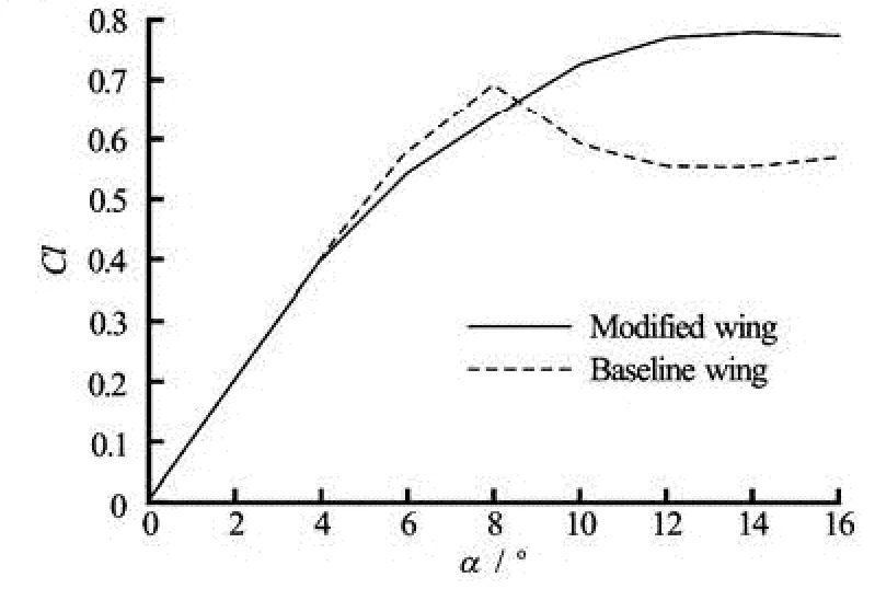
Fig.8 Lift coefficient at different angles of attack for two models at Re =106
3.1.2 Static wing in turbulent flow
The baseline wing and the modified wing with the wavy amplitude of 5% of chord length are studied in turbulent flow. The force curves of the two wings are shown in Fig.8. It is shown that in the post-stall range, the modified wing achieves a delayed stall as well as a higher lift as compared with the baseline wing. When the attack angle is small o (α≤6), the lift coefficient of the modified wing is similar to that of the baseline wing. The baseline wing causes stalls when the attack angle goes beyond of 6°. But the lift of the modified wing remains high in the range of 12 ° <α<20° , similar to the experimental results[2]. The lift of the modified wing here is higher than that of the modified wing with a thicker thickness at Reynolds number around 105, as shown in previous studies. Because the sections with decreased thickness tend to cause stalls at the leading edge in the form of short-bubble stalls, the flow control of the leading edge protuberances may be more effective for a thinner wing. The results of the present study are consistent with the suggestion of Stanway[13]that thinner foils operating at higher Reynolds number are more likely to have an increased maximum lift.

Fig.9 Vorticity contours of the modified wing at α=6° and Re=106
As discussed previously, the performance impro-vement is not caused by the non-uniform downwash. We will further discuss whether the vortex generation mechanism is operative.
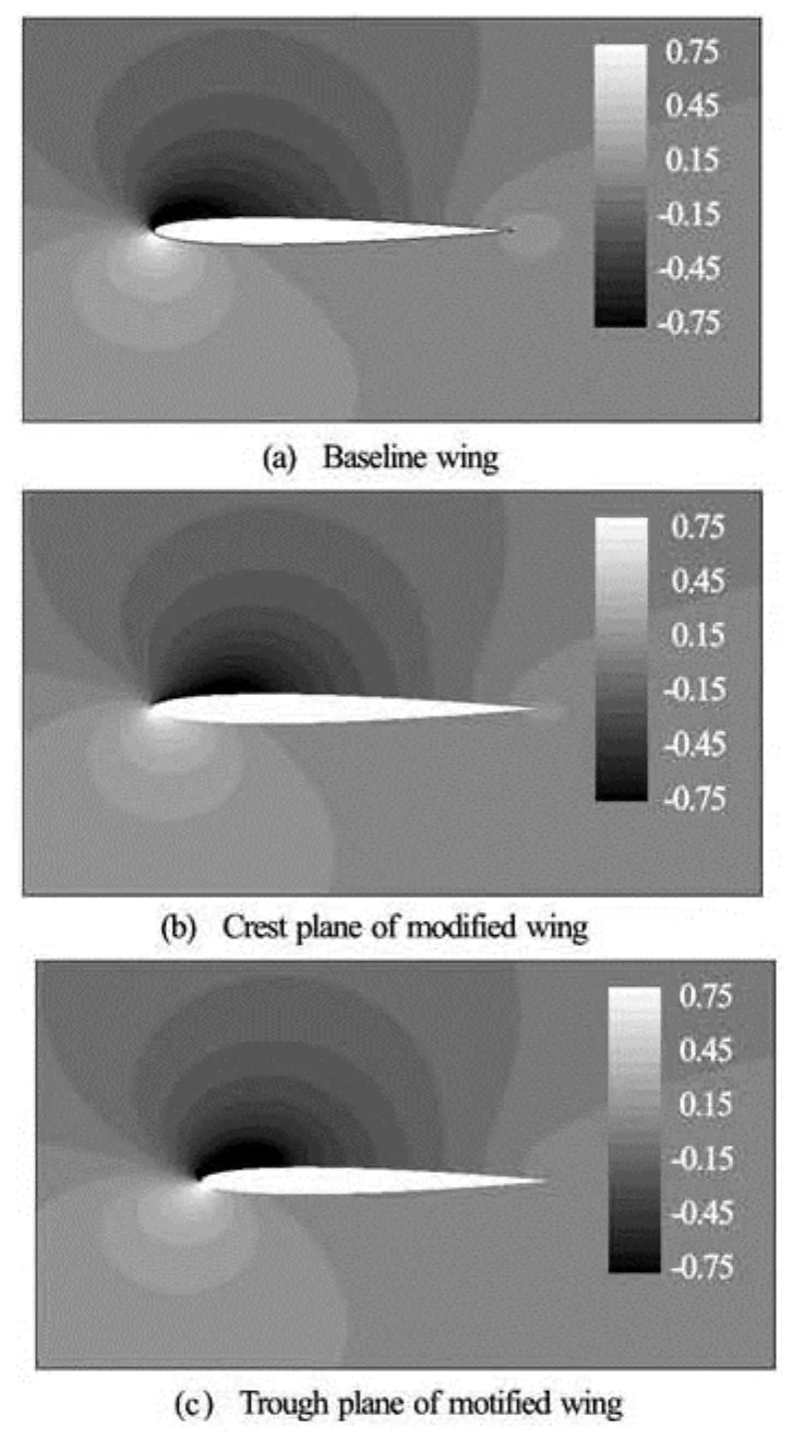
Fig.10 Pressure contours for two models at α=6°and Re= 106

Fig.11 The pathlines and pressure contours on the surface of wings at α=16°and Re =106
At a low attack angle (α=6°), the flow is steady. A pair of vortices with opposite signs is generated in the trough of the leading edge on the modified wing as shown in Fig.9. However, the pressure on the baseline wing is just between those in the crest plane and the trough plane of the modified wing (Fig.10).As a whole, the pressure is not changed much by this pair of vortices. Hence, the lift is almost the same for both wings.
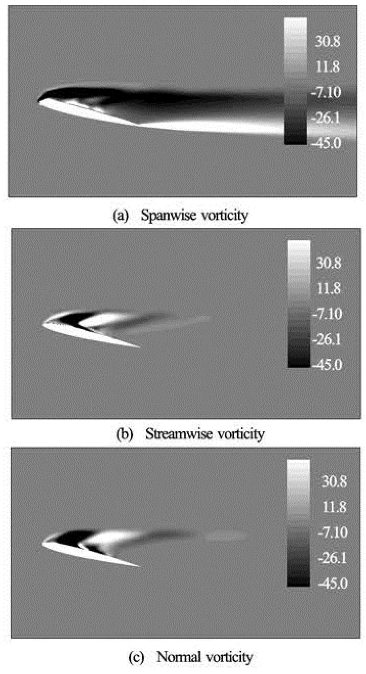
Fig.12 Vorticity components in three directions on the trough plane of modified wing at α=16oand Re=106

Fig.13 Time-dependent thrust coefficient of the pitching wings at Re=106

Fig.14 Vorticity of modified wing and baseline wing at αm =10o, k=3, Re=104

Fig.15 Pressure contours on the surface of pitching wings at αm =10o, k=3, Re=104
At angle attack of 16o, the flow field is unsteady. Figure 11 shows that a much more complex vortex structure emerges over the modified wing. It is shown in Fig.12 that not only the streamwise vorticity component but also the normal vorticity component in the direction of lift appear in distinctive forms. The normal vorticity component is even stronger than the streamwise one. This vortex structure is also shown by Watts[1]. But their vortex structure is nearer to the trailing edge than that of the present results. It is because higher Reynolds number and thinner airfoil will be more likely to cause a leading edge stall. It is also found from Fig.11 that a pronounced region of flow attachment on the lifting surface of the modified wing is formed because the interference of the vortices could cause a greater momentum exchange within the boundary layer. Therefore, a lower pressure region is formed on the upper surface of the modified wing which contributes to the lift and the stall delay.
3.2 Pitching wing


Fig.16 Pressure contours of pitching wings in varies planes at α =10o, k=3, t=T, Re =104m

4. Conclusions
In this study, three-dimensional simulations are performed to investigate the influence of the biologically inspired leading edge protuberances on the hydrodynamic performance of the static wing and the pitching wing.
For the static wing in turbulent flow, our results confirm the suggestion that leading edge protuberances act in a manner similar to vortex generators. It is found that the modified wing causes a delayed stall as well as a higher lift over the baseline wing in the poststall range. Streamwise vorticity does contribute to the delay of stall as indicated by previous studies, while we further show that a strong surface-normal vorticity also plays an important role in the stall delay. The interference of these complex vortices could result in a greater momentum exchange within the boundary layer and thus help keep the flow attached to the lifting surface despite an adverse pressure gradient. Results of the static wing in laminar flow indicate that the protuberances have only a slight effect on the performance. And it could be deduced that the non-uniform downwash does not delay the stall in either laminar flow or turbulent flow.

Fig.17 Streamwise velocity contours of pitching wings at α =10o, k=3, t=T, Re =104m
For a pitching wing in turbulent flow, the leading edge protuberances have limited effect under the condition of our computation. Despite the more complex leading edge vortices induced by the protuberances, the pressure distribution of the baseline wing is between those of the modified wing in the crest plane and the trough plane. In addition, the thrust jet and the vortices in the vortices in the wake is not changed by the leading edge protuberances, unlike the suggestion of Stanway[13].
[1] WATTS P., FISH F. E. The influence of passive, leading edge tubercles on wing performance[C]. Proceedings of the Twelfth International Symposium on Unmanned Untethered Submersible Technology. Durham, New Hampshire, 2001.
[2] MIKLOSOVIC D. S., MURRAY M. M. and HOWLE L. E. et al. Leading-edge tubercles delay stall on humpback whale (Megaptera novaeangliae) flippers[J]. Physics of Fluids, 2004, 16: L39.
[3] CUSTODIO D. The effect of humpback whale-like leading edge protuberances on hydrofoil performance[D]. Master Thesis, Worcester, Mass, USA: Worcester Polytechnic Institute, 2007.
[4] Van NIEROP E. A., ALBEN S. and BRENNER M. P. How bumps on whale flippers delay stall: An aerodynamic model[J]. Physical Review Letters, 2008, 100(5): 054502.
[5] PEDRO H. T. C., KOBAYASHI M. H. Numerical study of stall delay on humpback whale flippers[C]. 46th AIAA Aerospace Sciences Meeting and Exhibit. Reno, Nevada, USA, 2008.
[6] FAVIER J., PINELLI A. and PIOMELLI U. Control of the separated flow around an airfoil using a wavy leading edge inspired by humpback whale flippers[J]. Comptes Rendus Mecanique, 2012, 340(1): 107-114.
[7] AMIRALAEI M. R., ALIGHANBARI H. and HASHEMI S. M. An investigation into the effects of unsteady parameters on the aerodynamics of a low Reynolds number pitching airfoil[J]. Journal of Fluids and Structures, 2010, 26(6): 979-993.
[8] LIU Cun-fang, WANG Mei-xia. A similarity method for laminar wake of power-law fluid flow around a flat plate[J]. Journal of Hydrodynamics, Ser. B, 2003, 15(6): 74-77.
[9] LU Xi-yun, YANG Jian-ming and YIN Xie-zhen. Propulsive performance and vortex shedding of a foil in flapping flight[J]. Acta Mechanica Sinica, 2003, 165(3): 189-206.
[10] AONO H., LIU H. Flapping wing aerodynamics of a numerical biological fl yer model in hovering fl ight[J]. Computers and Fluids, 2013, 85: 85-92.
[11] SHYY W., AONO H. and CHIMAKURTHI S. K. et al. Recent progress in flapping wing aerodynamics and aeroelasticity[J]. Progress in Aerospace Sciences, 2010, 46(7): 284-327.
[12] HU Wen-rong, YU Yong-liang and TONG Bin-gang et al. A numerical and analytical study on a tail-flapping model for fish fast C-start[J]. Acta Mechanica Sinica, 2014, 20(1): 16-23.
[13] STANWAY M. J. Hydrodynamic effects of leadingedge tubercles on control surfaces and in flapping foil propulsion[D]. Master Thesis, Cambridge, MA, USA: Massachusetts Institute of Technology, 2008.
[14] JOHARI H., HENOCH C. W. and CUSTODIO D. et al. Effects of leading-edge protuberances on airfoil performance[J]. AIAA Journal, 2007, 45(11): 2634-2642. [15] WEBER P. W., HOWLE L. E. and MURRAY M. M. et al. Computational evaluation of the performance of lifting surfaces with leading-edge protuberances[J]. Journal of Aircraft, 2011, 48(2): 591-600.
[16] SHELDAHL R. E., KLIMAS P. C. Aerodynamic characteristics of seven symmetrical airfoil sections through 180-degree angle of attack for use in aerodynamic analysis of vertical axis wind turbines[R]. Technology Report SAND80-2114, Albuquerque, NM, USA: Sandia National Laboratories, 1981.
[17] MCALISTER K., CARR L. and MCCROSKEY W. Dynamic stall experiments on the NACA0012 airfoil[R]. Technical Paper TP1100, NASA, 1978.
[18] MARTINAT G., BRAZA M. and HOARAU Y. et al. Turbulence modelling of the flow past a pitching NACA0012 airfoil at 105and 106Reynolds numbers[J]. Journal of Fluids and Strctures, 2008, 24(8): 1294-1303.
10.1016/S1001-6058(14)60100-1
* Project supported by the National Natural Science Foundation of China (Grant Nos. 11072152, 1472173).
Biography: WANG Ya-yun (1990-), Female, Master
HU Wen-rong,
E-mail: wrhu@sjtu.edu.cn
杂志排行

水动力学研究与进展 B辑的其它文章
- Pressure transient behavior of a slanted well with an impermeable fault*
- Numerical research on the mechanism of contaminant release through the porous sediment-overlying water interface*
- Experimental investigation on diffusive contaminant release from permeable sediment layer under unidirectional unsteady flow*
- A drifting trajectory prediction model based on object shape and stochastic motion features*
- Run-up of non-breaking double solitary waves with equal wave heights on a plane beach*
- The mechanical response of piles with consideration of pile-soil interactions under a periodic wave pressure*