Experimental study of flow field in interference area between impeller and guide vane of axial flow pump*
2014-06-01ZHANGHua张华
ZHANG Hua (张华)
Research Center of Fluid Machinery Engineering and Technology, Jiangsu University, Zhenjiang 212013, China Research Institute of Chemical Machinery, Hefei University of Technology, Hefei 230009, China,
E-mail: zhh091088@126.com
SHI Wei-dong (施卫东)
Research Center of Fluid Machinery Engineering and Technology, Jiangsu University, Zhenjiang 212013, China CHEN Bin (陈斌)
Research Institute of Chemical Machinery, Hefei University of Technology, Hefei 230009, China
ZHANG Qi-hua (张启华), CAO Wei-dong (曹卫东)
Research Center of Fluid Machinery Engineering and Technology, Jiangsu University, Zhenjiang 212013, China
Experimental study of flow field in interference area between impeller and guide vane of axial flow pump*
ZHANG Hua (张华)
Research Center of Fluid Machinery Engineering and Technology, Jiangsu University, Zhenjiang 212013, China Research Institute of Chemical Machinery, Hefei University of Technology, Hefei 230009, China,
E-mail: zhh091088@126.com
SHI Wei-dong (施卫东)
Research Center of Fluid Machinery Engineering and Technology, Jiangsu University, Zhenjiang 212013, China CHEN Bin (陈斌)
Research Institute of Chemical Machinery, Hefei University of Technology, Hefei 230009, China
ZHANG Qi-hua (张启华), CAO Wei-dong (曹卫东)
Research Center of Fluid Machinery Engineering and Technology, Jiangsu University, Zhenjiang 212013, China
(Received July 18, 2013, Revised September 18, 2013)
Axial flow pump is a kind of typical pumps with rotor-stator interaction, thus the measurement of the flow field between impeller and guide vane would facilitate the study of the internal rotor-stator interaction mechanism. Through a structural modification of a traditional axial flow pump, the requirements of particle image velocimetry (PIV) measurement are met. Under the condition of 0.8Qopt., the axial vortex is identified between impeller hub and guide vane hub, which is developed into the main flow and to affect the movement when the relative positions of impeller and guide vane at different flow rates are the same. Besides, the development and the dissipation of the tip leakage and the passage vortex in impeller passages are mainly responsible for the difference of the flow field close to the outer rim. As the flow rate decreases, the distribution of the meridional velocities at the impeller outlet becomes more non-uniform and the radial velocity component keeps increasing. The PIV measurement results under the condition of 1.0Qopt.indicate that the flow separation and the trailing vortex at the trailing edge of a blade are likely to result in a velocity sudden change in this area, which would dramatically destroy the continuity of the flow field. Moreover, the radial direction of the flow between impeller and guide vane on the measurement plane does not always point from hub to rim. For a certain position, the direction is just from rim to hub, as is affected by the location of the intersection line of the shooting section and the impeller blade on the impeller as well as the angle between the intersection line and the rotating shaft.
axial flow pump, tip leakage, passage vortex, radial velocity, axial velocity
Introduction
Axial flow pump is a kind of pumps with large discharge and low head. Its main flow passage components include impeller and guide vane and it is a system with typical rotor-stator interactions. Unreasonable design and matching of impeller and guide vane not only is responsible for the low efficiency of the unit, but also would generate a large vibration and noise to threaten its safe operation. Therefore, the measurement of the flow field between impeller and guide vane would facilitate the study of the internal rotor-stator interaction mechanism of the axial flow pump.
With the development of computational fluid dynamics (CFD), the CFD numerical calculation method is widely used in the performance prediction[1,2], and the studies of the internal flow field structure[3-5], themixed multiphase flow[6], the cavitation phenomenon[7], and the tip leakage[8,9], for axial flow pumps. However, the internal flow field of the axial flow pump is complex with a ternary unsteady viscous turbulence. With different turbulence scales near the high-speed rotating impeller surface, in the tip clearance, near other stationary wall and fully developed flow regions, the turbulence has a great effect on the accuracy of CFD numerical calculation. The visualization of the internal flow field of the axial flow pump thus has more important significance besides the experimental investigation of its external characteristics[10,11]. Currently, the testing approaches for the internal flow field of the axial flow pump mainly include the probe measurement[12,13], the laser Doppler measurement[14], the high-speed photography[15,16]and the PIV measurement[17-19]. Among them, the PIV measuring technique serves as a kind of non-contact metrology methods with a high precision and a good instantaneous capture ability. But it is not a common practice in the research of the internal flow field of the axial flow pump to use the PIV measurement method. Especially, there are few PIV visualization investigations for the rotor-stator interaction region of the axial flow pump.
In this paper, the model scaling and the PIV testbed transformation are made for the axial flow pump withns=700. Besides, the PIV measurement is employed to the axial flow field between impeller and guide vane to investigate the flow field structure under different working conditions and at different interference positions between impeller and guide vane. And meanwhile, the mechanism of the model pump is analyzed.
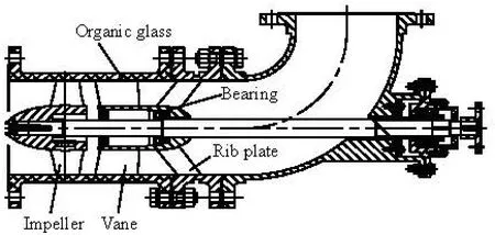
Fig.1 Pump assembly diagram for PIV experiment
1. Test device
1.1Hydraulic model
Design parameters of the prototype pump are as follows: the flow rateQ=1300 m3/h , the headH= 7.26 m, the rotating speedn=1450r/min and its specific speedns=700. The outer diameter of the impeller is 0.3 m and the original model is reduced, considering the cost of the test material and the processing. After the reduction, the outer diameter of the test pump is 0.2 m.
1.2Test pump section
Shown in Fig.1 is the final design of the test pump section. The impeller runner chamber and the casing of the guide vane are made as a whole to avoid the block effect of flanges with a traditional connection type on the axial flow field between the impeller and the guide vane. For the purpose of visualization, the chamber and the casing are made of organic glass with refractive index close to water. In addition, the cross section of the organic glass barrel is shaped into a square outside with a inner circle to simplify the optical refraction during the test. As the organic glass cannot bear a great radial force, the bearing in the guide vane body is set rearward, and rib plates are added at the location of the bearing to transmit the radial load produced during the pump operation on the foundation.

Fig.2 Piping system
1.3Piping system
The piping system (as shown in Fig.2) mainly consists of the water tank (about 26 m3in volume), the inlet valve, the outlet valve, the booster pump, the piezometric tube section, and the electromagnetic flowmeter.
2. Test data acquisition equipment
2.1The measurement of external characteristics
The external characteristics are measured with the torque method. Various data acquisition devices are used as follows:
The ZJ tacho-torquemeter is employed for the torque measurement, with a rated speed of 100 N·m and the number of teeth of 180. The accuracy grade is 0.2 and the range of speed is 0 r/min-6 000 r/min.
The LWGY-250 type turbine flow transducer is adopted to measure the flow rate. The nominal pressure is 1.6 MPa and the accuracy grade is 0.5.
WT-1511 intelligent capacitance pressure transmitter is adopted for the head measurement. The pressure transmitters are placed at the inlet and the outlet of the test pump, with the measurement ranges of ±100 kPa and 0 kPa-600 kPa, respectively. The accu-racy grade is 0.2. The output signal is 4 mA-20 mA and the working power supply is 20 V.
The measured data are all transferred to the measurement system of the pump products.
2.2PIV measurement
2.2.1 PIV system
The PIV system in the test is the commercial PIV system developed by TSI Inc.. It mainly consists of the following elements: the light source system (YAG200-NWL pulse laser, 610015-SOL light arm as well as lens group), the image collecting system (highspeed image acquisition card and 630059 frame straddling CCD camera), the synchronous control system (in internal and external trigger modes) and the postprocessing system (Insight 3G, Matlab and Tecplot 2008).
2.2.2 Synchronous system
During the measurement, in order to ensure the same blade position in each shooting, it is necessary to adopt a synchronous system. Due to the variable frequency starting, the external trigger synchronization system using fiber optic is applied to avoid the interference of the frequency converter on the external trigger pulse signal. The system is composed of a synchronous trigger controller and a fiber optic transmission converter. The former makes counts, delays the input shaft encoder signal, and triggers the output signal while the latter transforms the trigger impulse signal into a level signal required by the TSI synchronizer.
2.2.3 Tracer particle
Hollow glass sphere is chosen as the tracer particle in the test, with diameter of 20 μm-60 μm and density of 1 050 kg/m3. The following feature and the refraction performance of the tracer particle are close to those of water.
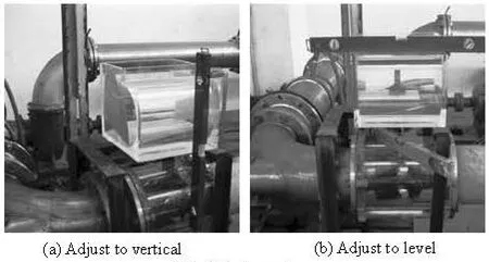
Fig.3 The process of calibration
2.2.4 Calibration method
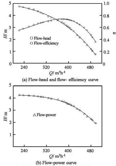
Fig.4 The external characteristic results of pump

Fig.5 The process of PIV experiment

Fig.6 The effect of tracer particle
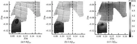
Fig.7 PIV measurement results of clearance between impeller outlet and guide vane inlet at different flow rates
To overcome the difficulty of the direct calibration inside the rotating machinery, a calibration water tank including a water tank and a baffle is used. They are made of organic glass, which are the same as the material of the impeller and the volute. The thickness of the water thank is equal to that of the volute, while the thickness of the baffle is equal to that of the impeller back shroud. The distance between the baffle and the water thank is equal to that between the impeller back shroud and the volute. During the calibration process (Fig.3), the positions of the water tank and the baffle are adjusted to make their fronts in the same plane. Cameras are translated to the side of the water tank through the a guide rail set on the camera frame which is customized. The thin ruler with scales are put on the measured plane. As the optical refractions for these two parts are the same, the pixels can be converted into the actual size according to the taken photos.
3. External characteristic experiment
Before the external characteristic experiment, an exhausting operation is carried out for the pipeline and the pressure acquisition equipment. And several groups of repetitive experiments are performed to ensure the stability of the experiment system. Depicted in Fig.4 are the final experiment results for external characteristics. From the results, it is seen that the flow rate reaches 383.1 m3/h at the maximum efficiency point of the model pump, where the head is 3.32 m and the efficiency reaches 73.79%.
4. PIV measurement
Figure 5 demonstrates the process and the arrangement of the relevant measurement equipment for this PIV measurement, mainly under conditions of 0.8Qopt., 1.0Qopt.and 1.2Qopt.(whereQopt.is the design point). Measurements are made for the axial flow field between the impeller and the guide vane. 80 groups of inter-related photographs are obtained each time, and then by averaging the processing results of every group of photographs, the actual flow field on the cross-section is obtained. Figure 6 is one of the 80 groups of inter-related photographs, from which it can be seen that the light source and the particle distributions in the measured plane are uniform, and that there is no obvious overexposure on the organic glass wall surface and the metal wall surface. A large proportion of tracer particles produce a micro-exposure, which means an ideal shooting effect.
4.1Relative position fixing of impeller and guide vaneThe cloud distribution of the relative speed and the 2-D streamline chart in the axial flow field under three conditions between the impeller and the guide vane are, respectively, illustrated in Fig.7, where it can be seen that there is an irregular vortex between the impeller hub and the guide vane hub. Under conditions of 1.0Qopt.and 1.2Qopt.,the development range of vortex is limited in the diameter range of the hub of the impeller and the guide vane. As the flow rate drops to 0.8Qopt., some vortexes go beyond the diameter range of the hub, and block the flow field near the root of the impeller outlet. Thus, the distance between the guide vane hub and the impeller hub is to be shortened, or a spigot with large clearance fit should be applied to avoid the vortex in the flow field.

Fig.8 The tip leakage vortex
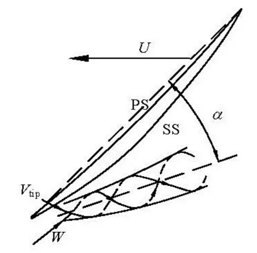
Fig.9 The formation principle of tip leakage vortex

Fig.10 The flow pattern near the tip

Fig.11 Distributions ofVxandVyalongYaxis at postionX=0.1094 m at different flow rates

Fig.12 Postions at various times

Fig.13 Four shooting positions
The area where the streamlines suddenly deflect near the wall surface of the organic glass barrel at three different flow rates is extended with the decrease of the flow rate. The initial position (as shown as the red dotted line in Fig.7) of such area moves closer to the stream-end with the decrease of the flow rate. Combined with the shape of the tip leakage vortex in the axial flow pump (Fig.8) given by[20], as well as the formation mechanism of the tip leakage vortex in the axial flow pump (Fig.9), it can be deduced that the main flowWrolls up the tip leakage flowVtipand dition of 0.8Qopt.comes earlier. Moreover, under the condition of 0.8Qopt., the pressure difference between generates a passage vortex in the flow passage. The vortex develops and is dissipated along the wall surface of the runner chamber in the direction opposite to that of the blade rotation. At a low flow rate, the pressure difference between the pressure surface PS and the suction surface SS is large and the effect of the leakage flow thus is great. The energy of the leakage vortex generated after the main rolling up leakage flow is high and the angleαbetween its motion direction and the blade chord is large. Furthermore, the passage vortex develops and reaches the shooting plane of PIV. Therefore, the deflection under the conthe pressure surface and the suction surface increases, so is the percentage ratio of the chord length to the area at the blade outer edge where the leakage emerges. As can seen in Fig.10, owing to the effect of the tip leakage, the flow rate at the outer edge on the pressure surface is insufficient, which leads to the deflection of the fluid nearby to the outer edge to replenish the flow field at the outer edge. Therefore, this effect can enhance the reflection tendency and the range at alow flow rate. As the flow rate grows, the intensity of the passage vortex and the angleαdecrease, and the pressure difference between the pressure surface and the suction surface drops, which results in a decrease of the leakage range at the blade outer edge. Thus the low-speed area near the organic glass barrel and the area of the streamline deflection slightly move to the end of the guide vane.

Fig.14 PIV measurement results of four different positions
From the 2-D streamline in the middle of the flow passage, it is shown that the streamline is almost parallel to the axis under the condition of 1.2Qopt., and the angle between the streamline and the axis becomes larger with the decrease of the flow rate. Furthermore, there is a local high-speed area for three different flow rates, respectively, as demonstrated in the velocity cloud picture. Above analysis indicates that the projection of the passage vortex on the cross-section in Fig.7 is a clockwise flat vortex, but the highspeed area in the middle of the flow passage at three different flow rates is located under the flat vortex. As the flat vortex rotates clockwise, one part of its energy is dissipated by the frictional resistance on the wall surface. The viscous resistance of the fluid consumes another part of its energy, and it plays a role of hindering the incoming flow near the wall surface, but the motion accelerates the incoming flow.
The distributions of the axial velocityVxand the radial velocityVyat positionX=0.1094 m are, respectively, depicted in Fig.11. As is seen from Fig.11(a), under the conditions of 1.2Qopt.and 1.0Qopt., the axial velocityVxdistribution is gentle along theYaxis, and it drops near the hub and the rim because of the influence of the boundary layer. Nevertheless, the degree of declining under the condition of 1.2Qopt.is greater than that under the condition of 1.0Qopt.in the place close to the rim. This is because that the passage vortex just develops through the positionX=0.1094 m on the shooting cross-section, while under the condition of 0.8Qopt., due to the influence of the vortex between the impeller hub and the guide vane hub, the distribution of the axial velocityVxat a location of small radius fluctuates strongly and the distribution at a location of large radius is similar to that under the condition of 1.0Qopt..
As for the average ofVyalongYaxis in Fig.11(b), the velocity component along the radial direction on the shooting plane increases with the decrease of the flow rate. From the distribution tendency ofVyalongYaxis, it is indicated that the curve ofVyhas a descending tendency under the condition of 0.8Qopt.. This is because one part of vortex between the impeller hub and the guide vane hub develops into the main flow area hindering the motion of the main flow, which increases the component of the main flow along the radial direction. As the radius increases to the outer rim,Vydecreases owing to the effect of the organic glass wall surface on the fluid. Under the conditions of 1.0Qopt.and 1.2Qopt., the vortex does not pose a great problem in the main flow area, and the curve ofVyshows an upward tendency owing to the effect of the passage vortex motion and the development near the outer rim.
4.2Relative position motion of impeller and guide vane
In order to investigate the mutual interference between the relative positions of the impeller and the guide vane at various instants, 4 relative position planes are chosen. The impeller of the axial flow pump in the experiment has 4 blades, and the guide vane has 7 blades. The blades of both components are regarded as axisymmetrical distributed, and the guide vane is considered as the stationary component, and the impeller is considered as the rotating component with rotatio-nal speedn=1450 r/min . 4 representative positions located at intervals of 22.5oare considered. It means the time difference is 0.0025862 s. Shown in Fig.12 is the four selected planes.
For the four cross-sections of different relative positions of the impeller and the guide vane, Fig.13 and Fig.14, respectively, illustrate the shooting effect and the processing result of the PIV under the condition of 1.0Qopt..
As shown in Fig.14, obvious differences are seen in the internal vortex form and the number of vortex core between the impeller hub and the guide vane hub, where 1, 0, 3 and 2 apparent vortexes appear at Positions 1 to 4, respectively. However, with consideration of the continuity of the main flow field, a sudden change of velocity only emerges occurs in the flow field at Position 3 and sudden turns also appear in the 2-D streamline. Combined with Fig.13(c), it is found that, at this moment, the impeller trailing edge exactly rotates through the shooting cross-section of the PIV. The flow separation and the generation of the trailing vortex occur at the impeller trailing edge and they develop into the shooting cross-section, resulting in the phenomenon at Position 3. From Figs.14(a) and 14(b), the flow fields in the main flow areas at the two positions are similar. This is because at these two positions, the cross-section intersects with the impeller blade near the trailing edge and in the middle. Under the anticipated condition, the tip leakage is unlikely to occur in the middle and at the rear of the impeller, and the intersecting lines of the two positions with the impeller blade are located far away from the inlet edge of the guide vane blade, which means that the interference is small.
For quantitative analyses of the interference effect between the impeller and the guide vane, the distributions of the axial velocityVxand the radial velocityVyalongYaxis at positionX=0.1094 m are compared (Fig.15). As demonstrated in Fig.15(a), two crests and one trough only arise in the distribution curve ofVxat Position 3. Although flow separation and the trailing vortex occur at the trailing edge of the impeller blade as seen from Fig.14, the trailing edge of the impeller blade is located on a quadrant angle. So the circumferential distance every time between the blade trailing edge and the shooting cross-section is different, and the degrees of the flow separation and the trailing vortex at the trailing edge are also different for every airfoil of the impeller blade under the same condition, which leads to an uneven distribution ofVxat Position 3. The distribution trends ofVxat Positions 1, 2 and 3 are close to each other, but the average ofVxat Position 3 is smaller than those at Positions 1 and 2.
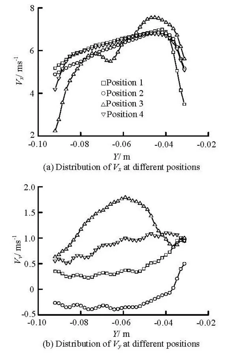
Fig.15 Distribution ofVxandVyalongYaxis at positionX=0.1094 m . 0.004 m under condition of 1.0Qopt.
From Fig.15(b), it can be seen that the radial velocity components at the positionX=0.1094 m on all cross-sections do not deflect from the hub to the rim, while in most area at Position 2, the radial velocity components deflect from the rim to the hub and the radial velocity components just deflect outward under the effect of the motion and the development of the passage vortex, mainly due to the angle between the rotating axis and the intersecting line of the shooting cross-section and the impeller blade and the position on the impeller blade. The distributions ofVyat Positions 1 and 4 both keep a monotone increasing trend, but the average ofVyat Position 1 is much larger than that at Position 4. The distribution ofVyat Position 3 is just in the opposite trend to that ofVx, a trend of low values at both ends, and a high value at the middle.
5. Conclusion
Through the 2-D PIV measurements of the flow between the impeller and the guide vane in an axial flow pump, the distributions of the flow field at the same positions at different flow rates are obtained, as well as those at different relative positions at the same flow rates. Not only the effect of the irregular axialvortex between the impeller hub and the guide vane hub on the main flow area is revealed, but also several other main features of aggravating the interference between the impeller and the guide vane are identified, such as the tip leakage, the development and the dissipation of the passage vortex and the flow separation and the trailing vortex at the trailing edge of the impeller blade.
[1] LIANG Kai-hong, CAO Shu-liang and CHEN Yan et al. Large-eddy simulation and analysis of turbulent flow in axial pump impeller[J]. Fluid Machinery, 2009, 37(11): 9-14(in Chinese).
[2] ZHANG De-sheng, PAN Da-zhi and XU Yan et al. Numerical investigation of blade dynamic characteristics in an axial flow pump[J]. Journal of Thermal Science, 2013, 17(5): 1511-1514.
[3] SAITO S., SHIBATA M. and FUKAE H. et al. Computational cavitation flows at inception and light stages on an axial-flow pump blade and in a cage-guided control valve[J]. Journal of Thernal Science, 2007, 16(4): 337-345.
[4] QIAN Zhong-dong, WANG Yan and HUAI Wen-xin et al. Numerical simulation of water flow in an axial flow pump with adjustable vanes[J]. Journal of Mechanical Science and Technology, 2010, 24(4): 971-976.
[5] MINER S. M. 3-D viscous flow analysis of an axial flow pump impeller[J]. International Journal of Rotating Machinery, 1997, 3(3): 153-161.
[6] TREMANTE A., MORENO N. and REY R. et al. Numerical turbulent simulation of the two-phase (liquid/ gas) through a cascade of an axial pump[J]. Journal of Fluids Engineering, 2002, 124(2): 371-376.
[7] ZHANG Rui, CHEN Hong-xun. Numerical analysis of cavitation within slanted axial-flow pump[J]. Journal of Hydrodynamics, 2013, 25(5): 663-672.
[8] LIANG Kai-hong, ZHANG Ke-wei and XU Li. Analysis of the flow through the blade tip clearances of axial pumps by CFD[J]. Journal of Huazhong University of Science and Technology: Nature Science Edition, 2004, 32(9): 36-38(in Chinese).
[9] DAI Chen-chen. Numerical analysis of tip clearance flow characteristic in axial flow pump[J]. Fluid Mechinery, 2009, 37(6): 32-35(in Chinese).
[10] FURUKAWA A., SHIGEMITSU T. and WATANABE S. Performance test and flow measurement on contrarotating axial flow pump[J]. Journal of Thermal Science, 2007,16(1): 7-13.
[11] DURMUS K. Experimental study on regaining the tangential velocity energy of axial flow pump[J]. Energy and Management, 2003, 44(11): 1817-1829.
[12] ZHANG De-sheng, SHI Wei-dong and CHEN Bin et al. Unsteady flow analysis and experimental investigation of axial-flow pump[J]. Journal of Hydrodynamics, 2010, 22(1): 35-43.
[13] LI Zhong, YANG Min-guan and WANG Xiao-kun. Experimental study of guide vane influence on performance of axial-flow pump[J]. Drainage and Irrigation Machinery, 2009, 27(1): 15-18(in Chinese).
[14] SHIGEMITSU T., FURUKAWA A. and WATANABE S. et al. Experimental analysis of internal flow of contra-rotating axial flow pump[C]. Proceedings of 8th International Symposium on Experimental and Computational Aerothermodynamics of Internal Flows. Lyon, France, 2007.
[15] TORU S., AKINORI F. and SATOSHI W. et al . Air/ water two-phase flow performance of contra-rotating axial flow pump and rotational speed control of rear rotor[C]. ASME Fluids Engineering Division Summer Meeting and Exhibition. Houston, TX, USA, 2005.
[16] SUN Z., KANG X. Q. and WANG X. H. Experimental system of cavitation erosion with water-jet[J]. Materials and design, 2005, 26(1): 59-63.
[17] ZHNAG Hua, CHEN Bin and SHI Wei-dong et al. Effect of contraction-type impeller on non-overloaded perfoemance for low-specific-speed sewage pump[J]. Journal of Mechanical Science and Technology, 2014, 28(3): 937-944.
[18] UZOL O., CHOW Y. C. and KATZ J. et al. Unobstructed particle image velocimetry measurements within an axial turbo-pump using liquid and blades with matched refractive indices[J]. Experiments in Fluids, 2002, 33(6): 909-919.
[19] WU H., MIORINI R. L. and KATZ J. Measurements of the tip leakage vortex structures and turbulence in the meridional plane of an axial water-jet pump[J]. Experiments in Fluids, 2011, 50(4): 989-1003.
[20] SHI Wei-dong, ZHANG Hua and CHEN Bin et al. Numerical simulation of internal flow in axial-flow pump with different blade tip clearance sizes[J]. Journal of Drainage and Irrigation Machinery Engineering, 2010, 28(5): 374-377(in Chinese).
10.1016/S1001-6058(14)60098-6
* Project supported by the National Twelfth Five-year Supporting Plan of China (Grant No. 2011BAF14B01), the Priority Academic Program Development of Jiangsu Higher Education Institutions, also by Graduate innovation program of Jiangsu Province (Grant No. CXLX12_0643).
Biography: ZHANG Hua (1988-), Male, Ph. D.
CHEN Bin,
E-mail: chenbin21cn@126.com
猜你喜欢
杂志排行

水动力学研究与进展 B辑的其它文章
- Non-spherical multi-oscillations of a bubble in a compressible liquid*
- Wind-wave induced dynamic response analysis for motions and mooring loads of a spar-type offshore floating wind turbine*
- Theoretical and experimental studies of the transport process of micro-particles in static water*
- Wave-induced flow and its influence on ridge erosion and channel deposition in Lanshayang channel of radial sand ridges*
- An analysis of dam-break flow on slope*
- Performance of the bio-inspired leading edge protuberances on a static wing and a pitching wing*