Experimental study of shock interacting with well-controlled gas cylinder generated by soap film
2014-03-29LuoXishengWangXianshengChenMojunZhaiZhigang
Luo Xisheng, Wang Xiansheng, Chen Mojun, Zhai Zhigang
(Advanced Propulsion Laboratory, Department of Modern Mechanics, University of Science and Technology of China, Hefei 230027, China)
0 Introduction
The Richtmyer-Meshkov (RM) instability[1-2]occurs on an initially perturbed interface subjecting to a sudden acceleration by a shock. Due to the deposition of baroclinic vorticity, the initial perturbation will grow with time, which generally intensifies the mixing between fluids and eventually induces turbulence in flow. Because of its academic significance in vortex dynamics and turbulent mixing as well as wide applications ranging from inertial confinement fusion[3], supernova explosions[4]to supersonic combustion[5], the hydrodynamic instability becomes increasingly attractive. Specifically,several comprehensive reviews on this topic have been made[6-8]. As a basic and simple RM instability problem, the shock-gas cylinder interaction has been extensively studied in experiments[9-14]. A great challenge to perform such experiments is to form a well-defined initial interface. Most previous experimental studies are performed in shock tube environments with a discontinuous or continuous interface. The creation of a sharp interface generally adopts a nitrocellulosic membrane[2,15]or a soap film[9,16-19]to separate the test gas from the ambient gas. The advantage of using the membrane or film is that diffusion between the test gas and surrounding gas is eliminated. However, due to the absorption of the fluid kinetic energy, the remaining membrane/film pieces are found to be influential in the late-time evolution. It is also hard to obtain the exact shape of initial perturbations in the experiment. Therefore, the approximate initial conditions were employed in the past numerical attempts, and the wire mesh supports were often simply neglected. To avoid the influences of membrane and support, the technique of gas cylinder[10,14,20]to form a continuous interface is developed. However, this technique for continuous interface has its own drawbacks. Taking the gas cylinder of SF6(sulfur hexafluoride) for example, the SF6gas falls through the test section due to gravity. Therefore, the gases in and near the cylinder column will attain a vertical velocity. Due to diffusion and mixing, the gas composition is not uniformly distributed on longitudinal and radial directions. The cross section of the gas column may deviate from the desired circular symmetry during the experiment. Therefore, the exact initial conditions such as the distribution of the gas concentration and the small vertical velocity of the gas column have to be determined afterwards, and effects of them on the instability are not fully understood as these experimental uncertainties genuinely introduce three-dimensional (3D) influences[21]. In the present study, a novel method to create a discontinuous gaseous interface is developed by the soap film technique for the RM instability study. The formed interface by the new method is free of supporting mesh and its initial shape can be accurately described in mathematics. Therefore, the initial condition can be well controlled.

(a)

(b)
1 Formation and feature of the initial interface
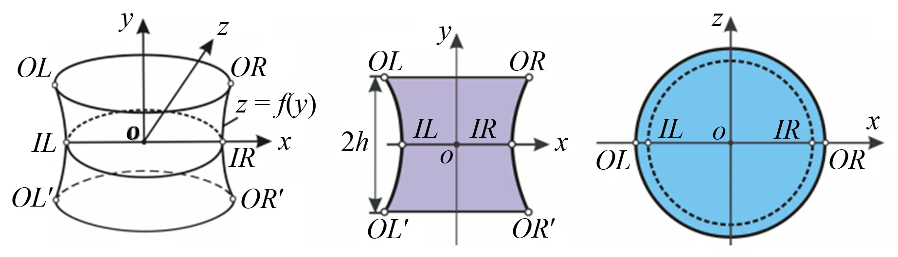
As sketched in Fig.1(a), two circular wires (35mm in diameter) are embedded into two quartz glasses (200mm×140mm) which are mounted in the visualizing window face-to-face. The wires with a thickness of 0.5 mm are made of acrylic sheets in a computer-aided design. In order to mount the wires, the quartz glasses are engraved on two circular channels. Firstly, the lower (for SF6) or upper (for helium) quartz glass is uniformly wetted by the soap liquid (made of 78% distilled water, 2% sodium oleate and 20% glycerine by mass). Then, a soap bubble is inflated with the test gas (SF6or helium) by a thin blowing pipe placed between the circular wires. This soap bubble firstly becomes a hemisphere bounded by the wire on the lower (for SF6) or upper (for helium) quartz glass, and then is expanding to the other quartz glass. A gaseous cylinder is formed when the bubble contacts with the wire on the other quartz glass. Based on the property of the soap film, the shape of the cylinder is closely related to the pressure inside the bubble[22]. An IC camera (Nikon D90) is used to monitor the geometry of the cylinder. Fig.1(b) shows the images of the two-dimensional (2D) and 3D gaseous cylinders and the dashed lines represent the interface boundaries. The 2D cylinder is formed with a little overpressure inside the inhomogeneity using the similar strategy adopted by Haas and Sturtevant[9]. However, the current 2D cylinder is made of soap film, which is considered to be less influential on the flow than thin plastic membranes[16-17]. The 3D cylinder is formed through making the pressure inside the inhomogeneity equal to the outside. This is realized by puncturing the soap film through a small perforation (2 mm in diameter) at the center of the circular wire in the quartz glass. Because the gas at both sides of the interface is at the ambient pressure, the formed 3D soap film interface has a zero mean curvature, i.e. two principal curvatures at every point of the interface are in opposite direction. Therefore, the formed 3D cylinder has a minimum surface feature[22-23]as depicted in Fig.2 together with its front-view and top-view. The surface can be accurately described in mathematics by
(1)
wherer0is the radius of the circle at the symmetric plane (y=0) andr0measured from the initial image is 13.7mm which agrees well with the prediction by Eq.1.
(a) (b) (c)
2 Experimental method
Experiments are conducted in a horizontal shock tube, which consists of a 1.7m driver section, a 2.0m driven section and a 0.6m test-section with the cross-sectional area of 140mm×20mm. The open-end tube is employed mainly for taking photos of the initial interface by the IC. The distance between the center of the initial interface and the open-end of the shock tube is 312mm, which corresponds to a test time of 1.4ms. The height of the test section is small (2h=20mm) to minimize the gravity effect of the test gas and to ensure a 3D interface formed in the shock tube. Note that, in order to create a 3D cylinder, the height of the shock tube must satisfy Eq.1 for a fixed radius of the circular wire (In the current situation, the radius of the circular wire is 17.5mm and the resulting maximum height of the shock tube is less than 23.2mm). The schlieren photography is employed to visualize the interaction of the shock wave with the 2D and 3D gaseous cylinders as shown in Fig.3. In order to maintain the shapes of the initial interface, the visualizing windows are arranged in the vertical direction. The illumination, provided by a DC regulated light source (DCR III, SCHOTT North America, Inc., 200W), is made accessible through a pair of quartz glasses (200mm×140mm) mounted in the visualizing window. A high-speed video camera (FASTCAM SA5, Photron Limited) is equipped to record the sequences. The timing and triggering system involves a four channel delay generator (DG645, Stanford Research Systems), two piezoelectric pressure transducers, a charge amplifier, an oscilloscope and some accessories. The frame rate of the high-speed video camera is 3×10⁴fps and the spatial resolution is 640×376 which implies 300mm/pixel. The local pressure and temperature are 101325Pa and 293K, respectively.
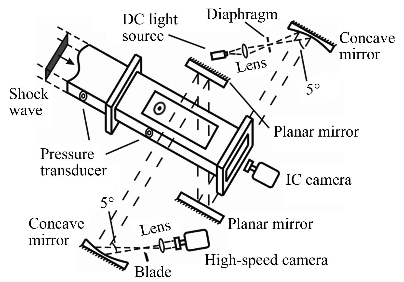
Fig.3 The schematic of the schlieren system
3 Results and discussion
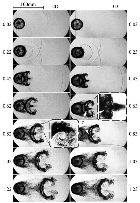
The morphologies of the shocked 2D cylinder with a diameter of 35mm and the corresponding 3D inhomogeneity with minimum surface feature are compared in Figs.4 and 5 by schlieren sequences. Helium or SF6is employed as the test gas in the cylinder, which produces a large density mismatching with the surrounding air. The incident shock wave propagates from left to right with a Mach number ofMs=1.2. All the records start when the incident shock wave collides with the gaseous cylinder. When the shock wave collides with the bubble either filled with helium or SF6, the incident shock bifurcates into a transmitted shock wave and a reflected wave whose type is either the shock, or the rarefaction due to the mismatch of acoustic impedance inside and outside the bubble. During the passage of the shock, the discrete inhomogeneity obtains the energy at a very short time and baroclinic vorticity is deposited on the interface due to the misalignment of the pressure and density gradients[8]. When the shock wave transmits away, the deposited vorticity drives the shear flow in the vicinity of the interface. The interface is then rolled up, and the vortex pairs gradually dominate the flow. Eventually, the flow becomes more turbulent and the mixing between fluids is greatly intensified. In general, the morphologies of the shocked 2D cylinders are similar with the observations in literature[9]. Therefore, a detail description of the interface evolution is skipped here. However, there are distinct improvements in our images. It can be found that there are fewer waves in the schlieren images and the evolving interface is more symmetric. These improvements can be ascribed to the new method of the interface formation. The formed interface is free of support and mesh, and, therefore, is free of disturbances caused by the support and mesh. The instability evolution on the 2D interface is found to be quite different from that in the case of continuous interfaces[14]. The main vortex and the secondary vortices are more pronounced in our results of the shocked 2D SF6cylinder, as shown in the inset of Fig.5 (at time 0.82ms). The jet is also stronger in our results. These phenomena can often be found in numerical simulations[24], but seldom seen in experiments.

(a) (b)
(a) (b)
The 3D effects on the interface morphologies are significant which can be directly found from the comparison between the 2D and 3D shocked cylinders. In the helium case as shown in Fig.4, the 3D shocked cylinder presents two downstream interfaces denoted by ‘a’ and ‘b’ in the schlieren at time 0.21ms. The two downstream interfaces correspond to the interfaces at the symmetric (y=0) and boundary (y=±h) planes, respectively. Because of the 3D effects, the intermediate-time morphologies are also quite different in the two cases. The 3D shocked helium cylinder begins to roll up and the vortex pair forms at time 0.61 ms, which are earlier than those in the 2D case. In the SF6case as shown in Fig.5, there are also two downstream interfaces appearing in the 3D shocked cylinder at time 0.43ms. However, different from the helium case, most parts of the two interfaces coalesce to one interface as time proceeds except the central part (denoted by ‘c’). This central part belongs to the downstream interface at the boundary plane. Because of the curved shape (in vertical direction) of the downstream interface, the transmitted shock from the downstream interface (from SF6to air) will form a Mach reflection near the boundary and cause a relatively high pressure zone just outside the downstream interface. Driven by this high pressure, the central part, as shown in the inset of the schlieren image at time 0.63ms, becomes larger with time and moves more slowly than the upstream interface. Finally, the central part merges with the upstream interface.
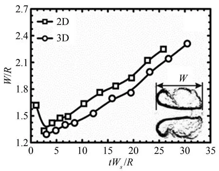
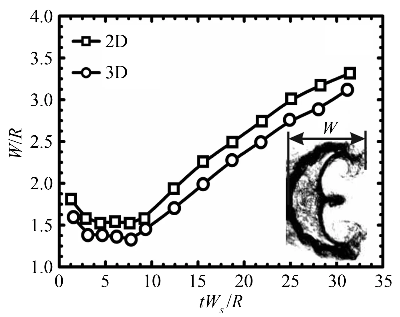
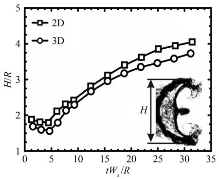
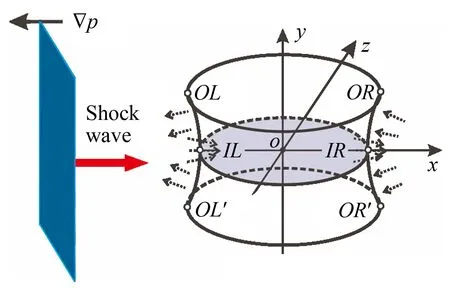
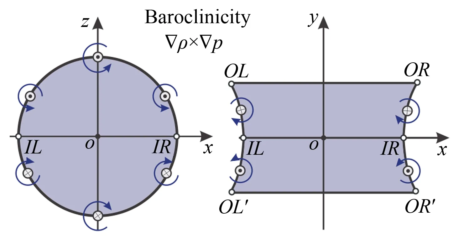
In order to compare the 2D and 3D cylinders quantitatively, the width and height of the interface structure are further measured, as given in Figs.6 and 7. All the quantities are normalized by the local characteristic length, which means that except that the width of the volume together with its time in the 3D helium case is normalized by the initial radius of the symmetric plane, other quantities are nondimensionalized by the initial radius of the cylinder, i.e. radius at the boundary plane. The reason is that the width in the 3D helium case is the distance between the upstream interface and the downstream interface at the symmetric plane (the interface denoted by ‘a’). It can be easily seen that the development of the shocked 3D cylinder is slower than that of the 2D counterpart, especially for the helium case. The pressure gradient and the baroclinic vorticity are supposed to be the driving mechanisms to account for the slowness, which is similar with the minimum surface case of 3D air/SF6interface in our previous study[23]. We shall first consider the width of the volume in the helium case. In the shock-helium in the helium case. In the shock-helium cylinder interaction, the direction of pressure gradient at pointIL/IR, induced by the reflected and transmitted waves in the horizontal (xz) plane, is to the left as depicted in Fig.8(a). However, in the cylinder with minimum surface feature, there is another pressure gradient, whose direction is to the right, induced by waves in the vertical (xy) plane. Therefore, the growth of perturbations at the symmetric plane tends to be suppressed by these opposite pressure gradients compared with the 2D counterpart. The baroclinic vorticity along the catenary line (OR-IR-OR′ orOL-IL-OL′) is also opposite to the one along the circular plane (xz), as illustrated in Fig.8(b), which also prevents the growth of the width at the symmetric plane. The slowness of the upstream height in the 3D helium case can be ascribed to these two factors. Because of the curved shape of the catenary lines of the 3D cylinder, there are ‘adverse’ baroclinic vorticity and pressure gradients exerting on the upstream interface. Therefore, the height of the upstream interface in the 3D cylinder increases more slowly than that in the 2D case at the early stage. Because of the earlier formation of the vortex pair in the 3D case as indicated in the schlieren images, the height of the 3D upstream interface begins to decrease earlier than that of the 2D case. For the SF6case, the extra pressure gradients and baroclinic vorticity caused by the minimum surface feature also prevent the interface development. Therefore, the quantities of the 3D case are all smaller than the 2D counterparts. It should be noted that in the SF6case the interface height, not the height of upstream interface as used in the helium case, is used because the vortex pair in this heavy gas case stretches the upstream interface and subsequently the upstream interface connects to the vortex pair. We can find that the interface height first experiences a small decrease due to shock compression and then increases with time because of the instability.
(a)

(b)
(a)
(b)
(a)
(b)
4 Conclusions
A simple method of generating gas cylinders is proposed by using the soap film technique. The formed interface is free of supporting mesh and the initial shape can be accurately described in mathematics. As a result, the schlieren images of the shocked 2D cylinder have less disturbing waves and the evolving interfaces are more symmetric comparing with the results in literature. Because of the sharp interface, the main vortex and secondary instabilities are more pronounced in our 2D results. Therefore, the quality of the experiments of the shock-cylinder interaction is improved by using the well-controlled initial condition and can provide a good benchmark for numerical codes and analytical models. Special attention is then given to the 3D effects caused by the minimum surface feature on the interface evolution. It is found that there are two downstream interfaces both in the 3D helium and SF6cases. The development of the shocked 3D cylinder is slower than that of the 2D counterpart, which can be ascribed to ‘adverse’ pressure gradients and baroclinic vorticity related to the 3D initial shape. Due to the 3D characteristic, the evolving interface at eachy-plane behaves differently and may interact with each other, which cannot be resolved by the integral visualizing method used in the present work. The effects of the liquid droplets produced by the soap film breakup, cylinder diameter, and shock Mach number on the RM instability also need further investigation.
Acknowledgements:This research was carried out with the support of the National Natural Science Foundation of China, Grant No. 10972214 and by the Knowledge Innovation Program of the Chinese Academy of Sciences, Grant No. CX2090050020. The authors would like to thank Dr. Si Ting and Mr. Wang Minghu for the valuable help during the experiments.
References:
[1]Richtmyer R D. Taylor instability in shock acceleration of compressible fluids[J]. Commun Pure Appl Math,1960, 13: 297-319.
[2]Meshkov E E. Instability of the interface of two gases accelerated by a shock wave[J]. Fluid Dyn, 1969, 4: 101-104.
[3]Lindl J D, Mccrory R L, Campbell E M. Progress toward ignition and burn propagation in inertial confinement fusion[J]. Phys Today, 1992, 45: 32-40.
[4]Arnett W D, Bahcall J N, Kirshner R P, et al. Supernova 1987A[J]. Annu Rev Astron Astrophys, 1989, 27: 629-700.
[5]Yang J, Kubota T, Zukoski E E. Applications of shock-induced mixing to supersonic combustion[J]. AIAA J, 1993, 35: 854-862.
[6]Zabusky N J. Vortex paradigm for accelerated inhomogeneous flows: visiometrics for the Rayleigh-Taylor and Richtmyer-Meshkov environments[J]. Annu Rev Fluid Mech, 1999, 31: 495-536.
[7]Brouillette M. The Richtmyer-Meshkov instability[J]. Annu Rev Fluid Mech, 2002, 34: 445-468.
[8]Ranjan D, Oakley J, Bonazza R. Shock-bubble interactions[J]. Annu Rev Fluid Mech, 2011, 43: 117-140.
[9]Haas J F, Sturtevant B. Interaction of weak shock waves with cylindrical and spherical gas inhomogeneities[J]. J Fluid Mech, 1987, 181: 41-76.
[10] Jacobs J W. The dynamics of shock accelerated light and heavy gas cylinders[J]. Phys Fluids, 1993, 5(9): 2239-2247.
[11] Tomkins C, Prestridge K, Rightley P, et al. A quantitative study of the interaction of two Richtmyer-Meshkov-unstable gas cylinders[J]. Phys Fluids, 2003, 15: 986-1004.
[12] Kumar S, Orlicz G, Tomkins C, et al. Stretching of material lines in shock-accelerated gaseous flows[J]. Phys Fluids, 2005, 17: 082107.
[13] Kumar S, Vorobieff P, Orlicz G, et al. Complex flow morphologies in shock-accelerated gaseous flows[J]. Physica D, 2007, 235: 21-28.
[14] Tomkins C, Kumar S, Orlicz G C, et al. An experimental investigation of mixing mechanisms in shock-accelerated flow[J]. J Fluid Mech, 2008, 611: 131-150.
[15] Mariani C, Vanderboomgaerde M, Jourdan G, et al. Investigation of the Richtmyer-Meshkov instability with stereolithographed interfaces[J]. Phys Rev Lett, 2008, 100: 254503.
[16] Layes G, Jourdan G, Houas L. Experimental study on a plane shock wave accelerating a gas bubble[J]. Phys Fluids, 2009, 21: 074102.
[17] Zhai Z, Si T, Luo X, et al. On the evolution of spherical gas interfaces accelerated by a planar shock wave[J]. Phys Fluids, 2011, 23: 084104.
[18] Si T, Zhai Z, Yang J, et al. Experimental investigation of reshocked spherical gas interfaces[J]. Phys Fluids, 2012, 24: 054101.
[19] Haehn N, Ranjan D, Weber C, et al. Reacting shock bubble interaction[J]. Combustion and Flame, 2012, 159: 1339-1350.
[20] Zou L, Liu C, Tan D, et al. On interaction of shock wave with elliptic gas cylinder[J]. J Vis, 2010, 13: 347-353.
[21] Weirs V G, Dupont T, Plewa T. Three-dimensional effects in shock-cylinder interactions[J]. Phys Fluids, 2008, 20: 044102.
[22] Isenberg C. The science of soap films and soap bubbles[M]. New York: Dover publications, INC., 1992.
[23] Luo X, Wang X, Si T. The Richtmyer-Meshkov instability of a three-dimensional air/SF6interface with a minimum-surface feature[J]. J Fluid Mech, 2013, 722, R2.
[24] Niederhaus Jhj, Greenough J A, Oakley J G, et al. A computational parameter study for the three-dimensional shock-bubble interaction[J]. J Fluid Mech, 2008, 594: 85-124.
Authorbiography:
罗喜胜(1971-),男,湖南沅江人,中国科学技术大学工程科学学院近代力学系教授、博士生导师。研究方向:高速流动中的相变与多相流动、激波管内RM不稳定性。通讯地址:安徽合肥中国科学技术大学工程科学学院近代力学系 (230027)。E-mail: xluo@ustc.edu.cn