Intelligent Identification of Wear Mechanism via On-line Ferrograph Images
2014-02-07WUTonghaiPENGYepingSHENGChenxingandWUJiaoyi
WU Tonghai *,PENG YepingSHENG Chenxing,and WU Jiaoyi
1 Key Laboratory of Education Ministry for Modern Design and Rotor-Bearing Systems,Xi’an Jiaotong University,Xi’an 710049,China
2 Reliability Engineering Institute,School of Energy and Power Engineering,Wuhan University of Technology,Wuhan 430063,China
1 Introduction
Wear debris analysis is one of the most comprehensive and intuitionistic methods for wear monitoring[1].With analytical ferrography,massive information of wear mechanism has been obtained by extracting the features of characteristic wear debris,such as morphology,color and texture[2].Moreover,the special analysis system has been developed for wear mechanism identification[3].However,there are still two inherent disadvantages for traditional analysis as the long monitoring interval and the experience-depended judgment[4].By now,ferrograph analysis has been confined in laboratory,thus was defined as an off-line means.Nowadays,condition based maintenance issued a new challenge of on-line and automatic monitoring,which limited analytical ferrography from further applications[5].Many sensors were developed for on-line monitoring,but most of the sensors provided numerical other than image signals[6].A newly developed on-line ferrograph sensor[7]provided a solution to this problem by providing on-line ferrograph images,which made real-time wear mechanism analysis feasible[8].However,the study on the real-time wear mechanism characterization was limited due to the difficulties in the feature extraction from on-line wear debris images.
Significant progresses in the effective feature extraction of the characteristic wear debris have been obtained in analytical ferrography[9].However,such achievements cannot be adopted directly in on-line image analysis.In practice,it is difficult to identify single wear debris from an on-line image due to the on-line features such as low resolution,high contamination and wear debris chains.Thus,statistical rather than precise description is more suitable for on-line analysis of wear debris images[10].In previous works,some attempts were performed on the statistical feature extraction of on-line wear debris images[5].
Accordingly,the study was carried out focusing on the capture of characteristic wear debris via on-line ferrograph sensor and the corresponding intelligent wear mechanism identification.The sampling parameters in the wear debris deposition were studied to achieve isolated wear debris in an on-line image.Furthermore,an artificial intelligence model was investigated to identify the wear mechanisms via the features of characteristic wear debris.
2 Characteristics of Wear Debris Deposition in On-line Ferrograph
2.1 Principle of on-line ferrograph image capture
The principle of on-line ferrograph is illustrated in Fig.1[11].The sensor is fixed in the machine’s return line.The lubricant from the machine’s return line follows through the flow channel of the sensor.The wear debris carried by the lubricant is deposited under the activated magnetic force.The images of the transmitted and reflected light are sequentially captured by the CMOS unit and stored in the computer.Finally,the magnetic force is released and the flow channel is flushed into the oil tank.The process is repeated periodically according to the above sequence until terminated by instruction.A typical transmitted image is shown in Fig.2.An index of particle coverage area(IPCA)can be calculated from the transmitted image as the quantitative indicator of wear debris concentration.

Fig.1.Schematic diagram of on-line visual ferrograph sensor system
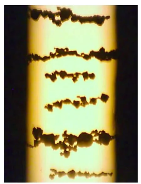
Fig.2.Transmitted image
2.2 Formation mechanism of wear debris chains in on-line ferrograph images
Wear debris chains are the main morphological characteristics of an on-line ferrograph image.The formation of wear debris chain is illustrated by a sequence of on-line images in sampling.As shown in Fig.3,wear debris was deposited consistently with time and gradually developed from isolated ones into chains.The process indicated that the wear debris morphology of an on-line ferrograph image was highly dependent on its deposition time.
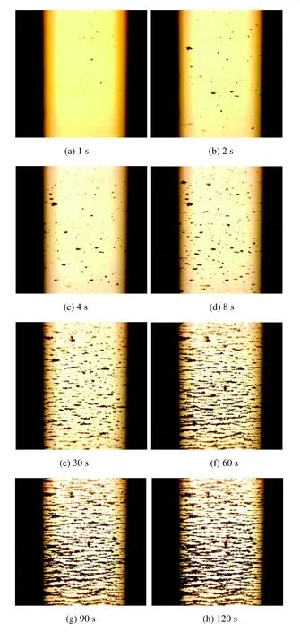
Fig.3.Wear debris was deposited with time
The formation mechanism of wear debris chains is illustrated in Fig.4.There is a uniform magnetic field between the magnetic poles.Wear debris passing-by is deposited and magnetized under the magnetic field.Correspondingly,a local reinforced magnetic field is formed around the deposited wear debris.When subsequent wear debris passes by the previously deposited one,it is attracted and deposited following the previously deposited one.The process is operated and recurred through the whole sampling process.Finally,wear debris chains appear as shown in Fig.4(c).

Fig.4.Formation mechanism of wear debris chains under magnetic field
Characteristic wear debris was the focus in analytical ferrograph.However,chains were the main morphological characteristic of wear debris in an on-line ferrograph image.Therefore,isolation of the wear debris from the wear debris chains is a basis.This has been accomplished in analytical ferrography by manual operation.However,the automatic segmentation of wear debris still remained an unsolved problem in on-line ferrography even though some analogous achievements have been obtained in regular particle segmentation,e.g.,adhesive cells[12].
Alternative idea was triggered from the deposition process as shown in Fig.3.For the initial images,isolated wear debris was the main morphology of the wear debris of the images.Therefore,the deposition time seems to be a key to solve the problem.
3 Acquisition of Characteristic Wear Debris in an On-line Ferrograph Image
Deposition time has influences on the acquisition of characteristic wear debris.Long time introduces wear debris chains,and short time reduces the probability of capturing characteristic wear debris.Therefore,determination of the deposition time adaptively is necessary effectively.
3.1 Deposition time in wear debris sampling
As shown in Fig.3,we can see that less deposition time corresponds with less wear debris,and then smaller IPCA.Accordingly,IPCA could be adopted as a simple and practical criterion for determining the deposition time.A well isolated image,as shown in Fig.3(d),has a small IPCA of 271 and a short deposition time of 8 seconds.However,sufficient sampling time is always needed to obtain enough wear debris,especially for relatively clean lubricant.A new sampling strategy referred as multi-sampling with short deposition time was proposed.
3.2 Multi-sampling route design
The previously adopted sampling route is shown in Fig.5.Only one sampling was designed in one cycle.The improved sampling route is shown in Fig.6.The sampling number was unfixed in advance but determined by the condition of“IPCA<200”.The condition was given according to the experiment result and could be changed in different applications.

Fig.5.Original sampling route
The advantage of the improved route was that the self-adaptability of the deposition time according to the wear debris concentration in the lubricant.As shown in Fig.7,the results of the improved sampling route exhibited a satisfactory effect in determining characteristic wear debris.
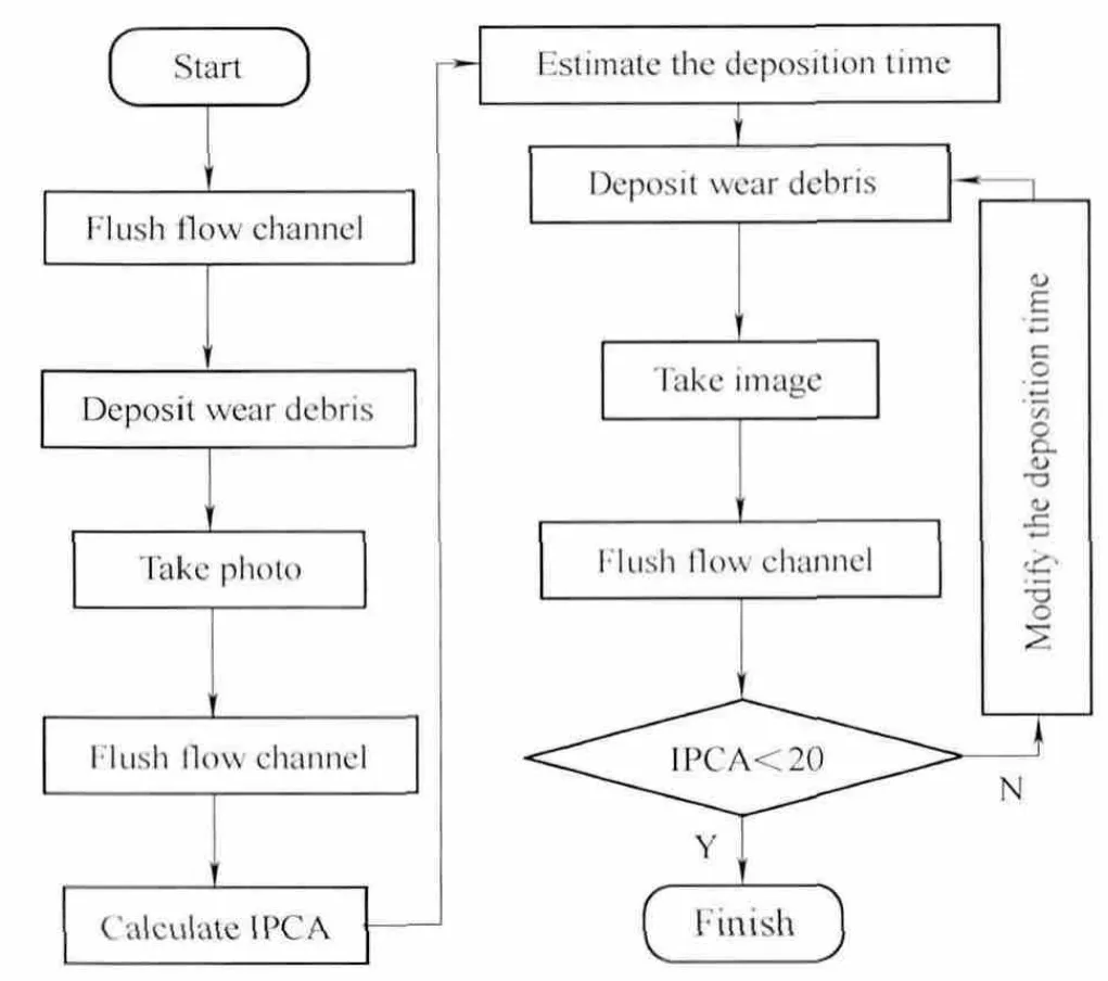
Fig.6.Improved sampling route
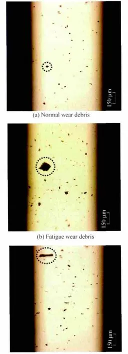
Fig.7.Samples of characteristic wear debris in on-line ferrograph images
4 Wear Mechanism of Characteristic Wear Debris Based on Feed-forward Neural Network
As the direct product of wear process,characteristic wear debris contains profound information of wear mechanism.For analytical ferrography,comprehensive achievements have been obtained in detailed feature extraction of wear debris to exactly analyze the wear mechanisms.While for on-line ferrography,the determination on wear mechanism was greatly limited due to poor image qualities and automation request.A primary identification method was studied for on-line wear mechanism characterization focusing on the rough morphological features of characteristic wear debris with a neural network model.
推门,进来,往桌子上放茶壶,放茶杯,放茶盘,放茶托,放茶洗,放茶针,放茶勺,放茶夹,放保温壶,静秋头也不抬。楚墨盯着近在咫尺的静秋,他看到碎发,伤疤,雾蒙蒙的眼睛,细蒙蒙的汗滴,红唇,均匀的脖子,微微翘起的下巴,长长的睫毛在眼睑处投下的小小阴影。他看着静秋,既不动,也不说话。心中瞬间云水掩映,烟波浩瀚,一叶轻舟驶进云水深处,渔歌唱晚,彩霞满天。
4.1 Extraction of features of characteristic wear debris
Characteristic wear debris was located and isolated in an on-line ferrograph image with the previously developed gray stack method[13].Contour features are concerned in the on-line identification by referring to analytical ferrography:equivalent dimension,length-width ratio,shape factor,and contour fractal dimension.The meanings of the four features were described as follows.
(1)Equivalent dimension
Equivalent dimension reflects the size of wear debris dimension and area statistically.It can be calculated as

where W1is the wear debris equivalent dimension,A is the total wear debris area.
(2)Length-width ratio
Wear debris length-width ratio is the ratio between the size of the long axis and short axis of wear debris.It is a very important parameter for distinguishing the cutting wear from other mechanisms.It can be calculated as

where W2is the wear debris length-width ratio,L is the size of wear debris long axis,W is the size of wear debris short axis.
(3)Shape factor

where W3is the wear debris shape factor,A is the total wear debris area,P is the edge parameter.The shape factor is in the range of 0 to 1.If the value of the shape factor is closer to 1,the wear debris shape is closer to a spheroid.Thus,the shape factor is an important parameter to identify spherical particle.
(4)Contour fractal dimension
The contour shape of wear debris is complex and irregular generally.Its characteristics have a certain relationship with friction’s wear conditions[14].The fractal dimension is a description of the capacity of wear debris contour and surface shape filling space.As research shown,wear debris contour has fractal feature[15].The fractal dimension is calculated by using the Mandelbrot coasting length measurement principle,approximating the actual contour to polygon,by changing the measurements and calculating the perimeter of polygon,which is available to obtain the relationship of measure and scale[16].For different steps of r,we can get the wear debris’s corresponding circumference N(r).Getting this data set on a bi-logarithm coordinates and then carrying out minimum variance linear regression can get the wear debris contour fractal dimension.Let xr=lg(r),yr=lg(N(r)),and the calculation formula is

where W4is the wear debris contour fractal dimension,x0is the average of xr,y0is wear debris projected area.
The three images in Fig.7 were processed to extract above features.The calculation results of the characteristic wear debris were given in Table 1.
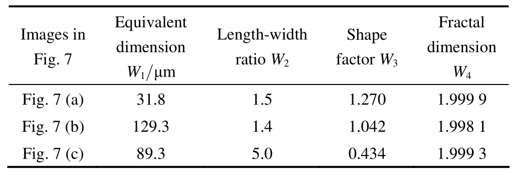
Table 1.Results of four features of characteristic wear debris in the images in Fig.7
4.2 Characteristic wear debris identification model
A model of forward feed-back neutral network was constructed for wear debris identification.The structure of network,as shown in Fig.8,contains three layers:input layer,output layer and hidden layer.The input layer contains four feature variables;the output layer contains four two-value variables.The number of the hidden layer’s nodes can be determined by experience firstly,and then improved by experiment.Considering efficiency and precision comprehensively,the hidden layer contains six nodes finally.

Fig.8.Structure of the forward feed-back neutral network for characteristic wear debris identification
According to analytical ferrography,the criterion for wear mechanism judgment was given in Table 2.Different combination of the output variables corresponds with different wear mechanisms.The model was realized by programming with the software VC++6.0.Due to the deficiency of on-line reference samples,some analytical ferrograph images were adopted as the training samples.Finally,a self-learning network model was obtained for on-line wear mechanism identification.

Table 2.Expected outputs of the forward feed-back neutral network
4.3 Application of Characteristic wear debris identification
Aiming at the on-line wear mechanism identification,the method designed in this paper was verified with some used engineering oil.With the automatic sampling route,some ferrograph images with characteristic wear debris were obtained as shown in Fig.9.According to analytical ferrography,the mechanisms of the characteristic wear debris were fatigue for Figs.9(a)and 9(c),cutting for Figs.9(b),9(d)and 9(e),and normal wear for Fig.9(f).
The four morphology features were extracted with the six images,respectively.The results were given in Table 3.The identification results by the network model were given in Table 4.By referring to the criterion in Table 2,the wear mechanisms were effectively identified.
Although more examinations were required to verify the model,the work makes a primary first step for on-line wear mechanisms identification.
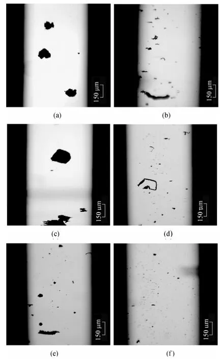
Fig.9.On-line ferrograph images with different characteristic wear debris
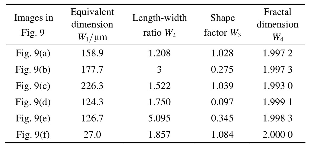
Table 3.Features of characteristic wear debris in the images in Fig.9
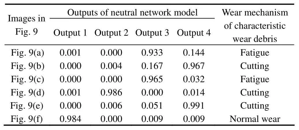
Table 4.Characteristic wear debris identification results with images in Fig.9
5 Conclusions
Aiming at the wear mechanism identification via characteristic wear debris with on-line ferrograph images,the sampling method and the identification model of characteristic wear debris were studied.Three main conclusions were drawn as follows.
(1)The formation mechanism of wear debris chains in on-line ferrograph image was illustrated.Accordingly,an improved sampling route for wear debris sampling was proposed and characteristic wear debris was identified from an on-line ferrograph image.
(2)Four contour features of characteristic wear debris were extracted from an on-line ferrograph image for wear mechanism characterization.
(3)The model for wear mechanism identification was constructed with a forward feed-back neutral network.The model with analytical ferrography knowledge could identify the wear mechanisms with on-line ferrograph images,which gives a meaningful exploratory for on-line wear monitoring.
[1]WANG Yonghong.The study of wear particle recognition based on ferrography[D].Hangzhou:Zhejiang University,2002.
[2]MACIAN V,PAYRI R,TORMOS B,et al.Applying analytical ferrography as a technique to detect failures in Diesel engine fuel injection systems[J].Wear,2006,260(4–5):562–566.
[3]RAADNUI S.Wear particle analysis-utilization of quantitative computer image analysis:A review[J].Tribology International,2005,38(10):871–878.
[4]ZHANG Yali,MAO Junhong,XIE Youbai.Engine wear monitoring with OLVF[J].Tribology Transactions,2011,54(2):201–207.
[5]WU Tonghai,WANG Junqun,WU Jiaoyi,et al.Wear characterization by an on-line ferrograph image[J].Proceedings of the Institution of Mechanical Engineers Part J:Journal of Engineering Tribology,2011,225(1):23–34.
[6]YUAN Chengqing,JIN Zhongmin,TIPPER J L,et al.Numerical surface characterization of wear debris from artificial joints using atomic force microscopy[J].Chinese Science Bulletin,2009,54(24):4583–4588.
[7]WU Tonghai,WANG Weigan,WU Jiaoyi,et al.Improvement on on-line ferrograph image identification[J].Chinese Journal of Mechanical Engineering,2010,23(1):1–5.
[8]WU Tonghai,MAO Junhong,WANG Jintao,et al.A new on-line visual ferrograph[J].Tribology Transactions,2009,52(5):623–631.
[9]XIAO Hanliang.The development of ferrography in China—some personal reflections[J].Tribology International,2005,38(10):904–907.
[10]WU Tonghai,WANG Junqun,PENG Yeping,et al.Description of wear debris from on-line ferrograph images by their statistical color[J].Tribology Transactions,2012,55(5):606–614.
[11]WU Tonghai,QIU Huipeng,WU Jiaoyi,et al.Image digital processing technology for visual on-line ferrograph sensor[J].Chinese Journal of Mechanical Engineering,2008,44(9):83–87.(in Chinese)
[12]KONG N S P,IBRAHIM H.Color image enhancement using brightness preserving dynamic histogram equalization[J].IEEETransactions on Consumer Electronics,2008,54(4):1962–1968.
[13]LIU Tonggang,TANG Xiaohuang,YANG Ziyi.The theory of debris group in ferrographic analysis[C]//Technical Sessions—Proceedings of CIST2008 &ITS-IFToMM2008,Beijing,China,2009:361–365.
[14]YAM JYF,CHOW TWS.A weight initialization method for improving training speed in feedforward neural network[J].Neurocomputing,2000,30(1–4):219–232.
[15]HUANG Chuanhui,ZHU Hua,GE Shirong.Study on relevance between contour fractal dimension of wear debris and wear state[J].Tribology,2003(4):336–339.(in Chinese)
[16]STACHOWIAK G W,PODSIADLO P.Surface characterization of wear particles[J].Wear,1999,225–229(2):1171–1185.
杂志排行
Chinese Journal of Mechanical Engineering的其它文章
- Investigation of CFD Calculation Method of a Centrifugal Pump with Unshrouded Impeller
- Experimental Model and Analytic Solution for Real-time Observation of Vehicle’s Additional Steer Angle
- Experimental Study on Occupant’s Thermal Responses under the Non-uniform Conditions in Vehicle Cabin during the Heating Period
- Optimizing the Qusai-static Folding and Deploying of Thin-Walled Tube Flexure Hinges with Double Slots
- Annoyance Rate Evaluation Method on Ride Comfort of Vehicle Suspension System
- Constant Speed Control for Complex Cross-section Welding Using Robot Based on Angle Self-Test
