Constant Speed Control for Complex Cross-section Welding Using Robot Based on Angle Self-Test
2014-02-07XUELongZOUYongHUANGJiqiangHUANGJunfenTAOXinghuaandHUYanfeng
XUE Long ,ZOU Yong, *,HUANG Jiqiang,HUANG Junfen,TAO Xinghua,and HU Yanfeng
1 Opto-Mechatronic Equipment Technology Beijing Area Major Laboratory,Beijing Institute of Petrochemical Technology,Beijing 102617,China
2 School of Automation Science and Electrical Engineering,Beihang University,Beijing 100191,China
3 SINOPEC Research Institute of Petroleum Engineering,Beijing 102200,China
1 Introduction*
As petroleum exploration is developed toward foreshore,offshore,deep and ultra deep wells,drilling becomes more and more difficult[1–3].Casing cement in the low pressure layer and mud loss layer as well as other complicated stratums is one of the difficult problems in drilling construction of deep wells,which restricts improvement of drilling technology of deep wells[4–5].
At present,Russian casing cement technology of expandable profile liner(EPL)is adopted in China.The casing cement technology of EPL is to process a circular pipe with cold-compressed treatment,which leads to plastic deformation in radial direction and cross-section of the pipe shows itself into ripple shape.Then outside diameter of the EPL can be reduced and it can get to the plugging stratum location through surface casings.The EPL is expanded by dint of hydraulic pressure and becomes a circular tube under the function of a expand tube.This is a new technology to plug complicated stratums[6–7].When drilling complicated stratums,using EPL technology the diameter of the original well can be kept with a reduction of construction difficulty and less economic investment,and the technology has more advantage than technic casing cement[8–9].
The length of single EPL is 10m in general.Hundreds of meters of EPLs need to be jointed together in field work under severe conditions.Welding is the primary connection technology for EPLs.Manual welding is adopted in all of welding construction of EPL so far.It takes a welder 3–4 h to run a bead,which induces a bottleneck in field work.The vast investment of other working procedures in petroleum prospecting cannot be brought into full play.Once there is something wrong with welding quality,hundreds of meters of pipeline in a well could not be expanded and strengthened normally,then the well would be discarded and resulting losses would be hard to imagine.Therefore,welding quality and efficiency of EPL are main factors that affect development of the technology[10].
A welding robot can ensure the welding quality of product and meet all the performance requirements with stable welding procedure conditions,meanwhile weld shaping is good and meets appearance quality requirements of product[11].EPL welding quality and efficiency can be improved greatly by developing an automatic welding robot of EPL.
A welding robot is a typical mechatronic product,its core technologies include four aspects:(1)structure technology[12];(2)information sensing technology[13–16];(3)motion planning technology[17–19];(4)intelligent control technology[20–22].Motion planning technology is divided into teaching and playback motion,joint space motion,spatial linear motion and spatial curvilinear motion.EPL cross-section welding requires a welding robot to achieve constant control of spatial curve.
To achieve the objective of being able to do automatic welding of EPL with a complicated cross-section trajectory,the authors developed a welding robot for EPL,and solved the problems of dynamic implementation of complex section trajectory and constant speed control of variable trajectory.
2 Statement of the Constant Speed Problem for Profile Welding with a Robot
There are two types of cross-section for EPLs,which include“8”type and cinquefoil type.The“8”type EPL is easy to be compacted and expanded,and it has a big expansion ratio.Compared with the“8”type EPL,the cinquefoil type EPL is not easy to be compacted and has a big strain after forming and expansion at the same expansion ratio.Non-circularity of the cinquefoil type EPL increases after expansion with uneven wall thickness,and its collapse resistance intensity is reduced.As a result,the“8”type EPL is studied in this paper,and its cross section shape is shown in Fig.1.

Fig.1.Schematic diagram of the cross section of EPL
The cross section of EPL has the following characteristics.
(1)Small shape size.Horizontal outside diameter of the EPL D1=225 mm;its wave height D2=178 mm;its waist depth H1=61 mm.Shape size of the whole cross section is small relatively.
(2)Composed of multi-segment arcs.The cross section of EPL is composed of multi-segment arcs.There are changes between outer arcs and inner arcs,as well as the radii of all the arcs are very different from each other.The minimum transition radius is r2=28 mm.
(3)Small wave trough.Arc radius of the trough r1=28 mm.Space for welding operation is small.
(4)Large forming error.As a result of limitations in pipe manufacturing technics,there are some forming error between an actual cross section and a designed section.
Based on the above characteristics,realization of automatic welding for the“8”type section of EPL requires that the adopted automatic welding equipment has several capacities,such as adaptability to the“8”type cross section seam,fast-response speed,large carrying capacity and a smaller welding actuator.Conventional automatic welding equipments cannot meet the above requirements.
Through the analysis to the cross section trajectory of EPL,it has been known that the complex cross section trajectory consists in a small dimension space with a steep gradient and small trough space.There is even no space to install a motor.The spatial attitude angle of the welding gun should be always perpendicular to the tangent of the welding trace and the operating speed of the end point of the welding gun along the welding trace surface is always uniform and invariable for automatic welding.So the problem of constant welding speed control for EPL was proposed.
It is a difficult problem to solve the attitude for trace realization and trace accessibility under the constraint of the boundary conditions presented above.The problem of constant speed control of a variable cross section trajectory is an unavoidable problem.
3 Welding Scheme and Mechanism Realization for EPL Robot
3.1 Mathematical description of the cross section trajectory of an EPL
Taking the medium size EPL for example,realization of motion trajectory and constant speed control were studied.Size and configuration Parameters of the cross section are shown in Fig.2.The coordinate system is established with the long axis as y axis and the short axis as x axis.
It can be seen from the parameters of the cross section trajectory that the complex trajectory section is symmetric with smooth-transition.Four quadrants in the coordinate system can be expressed with mathematical models approximately.Take the first quadrant for example;curve equations can be expressed as follows:
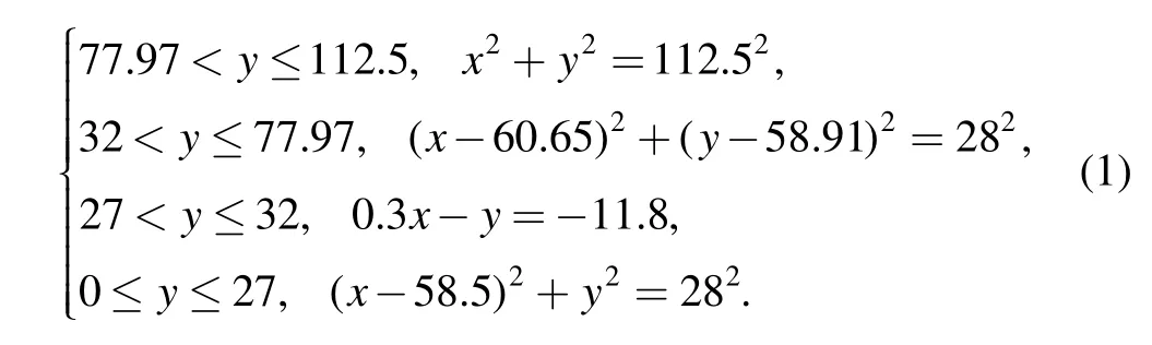

Fig.2.Quadrant chart for EPL
The other three quadrants can be described in the same way.Smooth curve trajectory without abrupt change in the four quadrants demonstrates that design of a smooth mechanical motion scheme for complete four quadrants is viable theoretically.
3.2 Realization of welding mechanism for the cross section of EPL
It is obvious through the above analysis that the conventional method of mechanical transmission is infeasible[23–27].It is difficult to install a drive motor bearing welding load for a trough r1=28 mm to ensure that the end of micro welding gun is always perpendicular to the welding groove.Even if the drive motor can be installed,it is hard to find a known accurate gesture for the welding torch during continuous welding due to manufacturing error of EPL and installation error of welding robot and accessibility of above trajectory welding is hard to implement.In other words,the realization condition of the above trajectory welding is that the attitude angle of the welding torch is perpendicular to the weld seam,and the end of the welding gun is equidistant from the weld seam.
From a practical point of view,the authors of this paper put forward a scheme of a small driven end actuator mechanism based on angle self-test to solve the self-adaptive control problem of welding torch perpendicularity and equidistance from weld seam.The advantage of this scheme is that we don’t need an accurate mathematical model to solve the angle problem.While the small end actuator moves along the trajectory,the attitude angle can be inspected automatically.The turning radius of the small end actuator is the height of the welding gun.As long as the small actuator is kept impacting the trajectory,the distance from the welding torch to the welding groove can be kept constant.
The welding robot system is shown in Fig.3,its mechanical structure includes the welding carriage,the circular orbit,the translation mechanism,the height tracking mechanism,the small driven end actuator and the small welding gun etc.

Fig.3.Schematic of mechanical structure of the welding robot for EPL
Because of the big curvature variation and small trough radius for the cross section of the EPL,the small tracking actuator moves along the surface contour of the EPL to achieve the operation of contour detection and tracking.On the other hand,the actuator needs to clamp the small welding gun to fulfil the welding task.As the actuator is very small with limited carrying capacity,most of the load work in the welding process is borne by the welding carriage.The circular orbit is installed on the EPL and the welding carriage moves along the circular orbit carrying the welding gun and cables.The translation mechanism and height tracking mechanism are used to connect the welding carriage with the small driven end actuator,and they work together to achieve automatic welding.
4 Modeling of Constant Speed Control for EPL
4.1 Vector model of constant speed for EPL
The driven end actuator is connected with the welding gun,and it has the same speed as welding.According to the analysis of the welding robot mechanism[28–29],the welding speed is the vector sum of speed vector of the welding carriage vcand speed vector of the height tracking mechanism vh(shown in Fig.4).
The vector sum v of the speed vector vcof the welding carriage and the speed vector vhof the height tracking mechanism is expressed as


Fig.4.Speed vector relation for the minitype driven actuator
By analyzing the above vector schematic diagram,it can be seen that the angle between the speed vector of the carriage vcand the speed vector of the height tracking mechanism vhis fixed(90º)during the welding process all around the EPL.While the constant welding speed v is known,the speed vectors vcand vhcan be acquired by awareness of either the angle between v and vcor the angle between v and vh.Actually angle measurement depends on the angle of minitype driven end actuator.
4.2 Quadrant constraint analysis of constant speed
equations for EPL
As shown in Fig.2,the cross section of EPL is distributed symmetrically in four quadrants,its contour size changes 12 times continuously along the circumference smoothly.There are four changes in each quadrant of the rectangular coordinate system.Since the four quadrants are symmetrical completely,the first quadrant is taken as an example for discussion and analysis of the speed constraint vector equations.
4.2.1 The first quadrant
In Fig.5,this curve segment(black line)is a circular arc centered in point O with a radius of R(R is not displayed).And it denotes the radius of the orbit,A1B1is height slider,and B1C1denotes the contour tracking mechanism.States of the mechanism at two different moments are shown in Fig.5.The purpose of speed control is to make sure that the welding gun is perpendicular to the seam all the time,that is,the welding gun is perpendicular to the cross section all the time.The speed of the welding gun is combination of the height slider speed v11and the carriage speed v12.As this section of curve and the orbit are concentric circles,there is no movement for the height slider.Speed v11=0,and the speed of contour tracking mechanism is the same as v12,that is

4.2.2 The second quadrant
In Fig.6,the curve segment(black line)is a circle arc centered in point O2with a radius of r2(r2is not display).States of the mechanism on this section of curve at two different times are shown in Fig.6.Motion of the mechanism from the preceding moment to the next moment(the interval between two moments is enlarged for convenient expression)is that the carriage turns around θ2,the height slider elongates automatically to adapt the curvature change of EPL.|C2E2|is length of the height slider at the next moment.In △B2D2E2,B2D2is a chord with origin O as the center and OB2as the radius.The elongation of the slider between two moments is|D2E2|.The curvature of the cross section of EPL section is different from that of the orbit on this section of curve.The velocity triangle is shown with a thick real line in Fig.6.v2is speed of the welding gun,which is perpendicular to the tangent of the welding gun’s location;v21is speed of the height slider,whose direction is the same as elongation direction of the slider;v22is speed of the carriage,which is always perpendicular to the slider,that is,it is perpendicular to v21.The contour tracking mechanism should be perpendicular to the cross section of EPL,so there is an angle between it and the slider.The angle is detected by an angle sensor which is indicated with α2.The angle between v21and v2is indicated with β2.The speed of the welding gun(v2)is composed of speeds of the slider(v11)and the carriage(v12).v11and v12can be calculated with Eq.(4)when v2is constant:
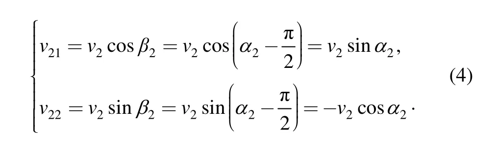

Fig.5.Speed model for the first section of curve
4.2.3 The third quadrant
In Fig.7,the curve segment(black line)is a straight line.The model shown in Fig.7 expresses states of the mechanism at two different moments on the third section of curve.The motion of the mechanism from the preceding moment to the next moment is that the carriage turns around θ3,the height slider elongates from|A3B3|to|D3F3|to adapt to the curvature change of EPL.In the triangle△B3E3F3,B3E3is a chord with origin O as the center and OB2as the radius,so the elongation of the slider between two moments is|E3F3|.The speed triangle on this section of curve is shown by a fine line in Fig.7:Speed of the welding gun is v3,and its direction is the same as the tangent all the time;speed of the height slider is v31,and its direction is in parallel to the slider location at present and along elongation direction of the slider;the carriage speed is v32,and its direction is along tangent of the orbit,so it is perpendicular to v31.The angle between the contour tracking mechanism and the height slider is α3,which is detected by the angle sensor.The angle between v31and v32is expressed by β3.The speed of the welding gun v3is the composition of the carriage speed v31and the height slider speed v32.When v3is constant,the other two speeds can be calculated by Eq.(5):


Fig.6.Speed model for the second section of curve

Fig.7.Speed model for the third section of curve
4.2.4 The fourth quadrant
In Fig.8,the curve segment(black line)is a circle arc centered in point O4with a radius of r1(r1is not displayed).States of the mechanism at two different moments on this section of curve are shown in Fig.7.The only thing that needs to be noted here is that length of the contour tracking mechanism(35 mm)is longer than the radius of the section of curve(28 mm).As the minitype driven end actuator attaches to the cross section all the time,the contour tracking mechanism is sure to pass through center of the circle(O4)no matter where it is and it is perpendicular to the cross section.Therefore,when the mechanism moves from the preceding moment to the next moment,the movement direction of the carriage is opposite to the previous direction.The motion of the height slider is divided into two cases:contraction in the first half section and elongation in the latter half section.

Fig.8.Speed model for the fourth section of curve
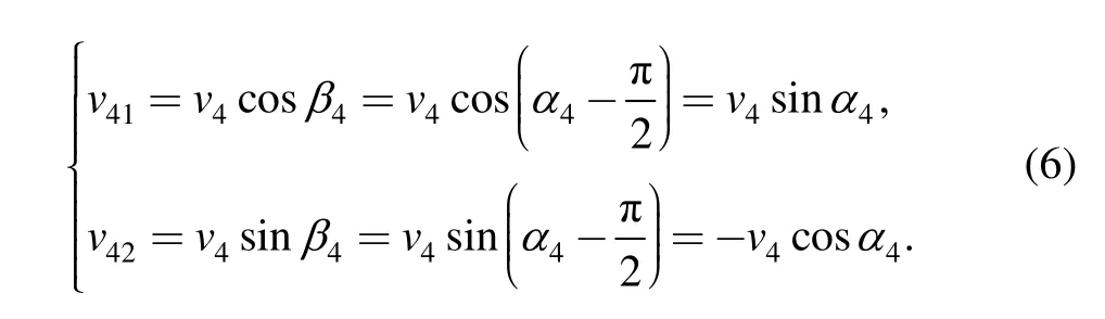
In the first half section,the carriage turns around θ4and the height slider contracts automatically from|D4F4|to|A4B4|with shrinkage of|E4F4|.The speed triangle of the welding gun at point C4is shown by a thick real line in Fig.8:speed of the welding gun at point C4is v4.According to the above analysis,speed of the height slider v41and speed of the carriage v42at point C4are equal and opposite to those at point B4.As shown in Fig.8,the angle(α4)between the contour tracking mechanism and the height slider is detected by the angle sensor,and the angle between v41and v4is expressed by β4.When v4is constant,the other two speeds can be calculated by Eq.(6):
4.3 Control of track profiling for EPL welding with the robot.
Cooperation work of the welding carriage and the small driven end actuator are realized through the height tracking mechanism.The height tracking mechanism is composed of a motor,a height slider and a pressure detection module.The height tracking mechanism makes the small tracking actuator attach to the surface of the EPL through the height adjustment motor.The pressure sensor is used to detect the pressure between the small tracking actuator and the surface of the EPL.The principle of the cooperation work for the mechanism based on pressure detection is shown in Fig.9.

Fig.9.Cooperation work principle for the mechanism based on pressure detection
In Fig.9,p0is a presetting value of pressure between the small tracking actuator and the surface of EPL.Under the pressure,the contour tracking mechanism attaches to the surface of EPL closely and moves neatly.The pressure(p)between the small tracking actuator and the surface of the EPL is detected by the pressure sensor in real time,and then it is compared with the preset value p0to obtain D-value(Δp).Δp is expressed by Eq.(7):
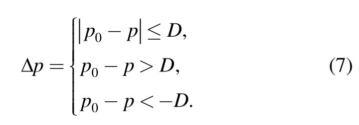
When Δp exceeds the allowed dead zone D,the control procedure of the height adjustment motor will be started,and forward or reversal rotation of the motor is controlled by the value of Δp[30–32].
Adjustment and control of the motor will be carried on when the absolute value of Δp is bigger than the allowed dead zone(D).If Δp is positive and bigger than the allowed dead zone(D),it means the attachment of the small tracking actuator to the surface of the EPL is not close enough.Therefore,the height adjustment motor needs to be turned forward to make the small tracking actuator attach to the surface of EPL closely,and the pressure value is close to the set value p0.If Δp is negative and its absolute value is bigger than the allowed dead zone(D),it means the attachment of the small tracking actuator to the surface of EPL is too close.Therefore,the height adjustment motor needs to be turned backward to make the small tracking actuator move away from the surface of EPL and the pressure value is close to the set value p0.
The small tracking actuator clamps the welding gun and moves along the surface of EPL in the welding process.The pressure detection device cooperates with the height tracking slider to make sure that the welding gun is always perpendicular to the surface of the workpiece.The welding operation can be achieved with the drive of the welding carriage and the cooperation of the corresponding welding control program.
5 Tests and Analysis
The welding robot developed in the paper was used to carry out EPL welding tests.Weld NDT and bulge tests were done to the welded EPLs to examine whether automatic welding quality of the welding robot can meet expansion requirements of oil well cementation.
5.1 Welding tests
EPL cross-section of 8-inch and 9-inch specifications used in the tests is shown in Fig.10.Two EPLs by inspection on request were selected,each was 1.5 m.Inside and outside surfaces of the specimens were cleaned before welding with no residue inside.

Fig.10.EPL cross-section
The welding procedure parameters of automatic welding of EPL with the welding robot are as follows.
(1)Welder:PULSE MIG-500;
(2)Shield gas:CO2;
(3)Wire specification:JM-56,φ1.0;
(4)Welding position:Horizontal welding;
(5)Welding current:140–150 A;
(6)Welding speed:25–30 cm/min.
The welding test with the robot is shown in Fig.11,and the weld of the welded EPL is shown in Fig.12.The tests show that the welding robot can achieve automatic welding of 8-shaped EPL with good weld appearance.

Fig.11.Automatic welding test of EPL

Fig.12.Welds of automatic welding of the robot
5.2 Welding specimens of EPL
According to expansion pressure test requirements of EPL,after specimens were selected and welded,V-RX portable X-ray NDT system was used for flaw detection of welding grooves.The NDT system includes a X-ray generator,an ICU(miniature imaging control unit),an imaging plate,a computer and cable etc.,as shown in Fig.13.

Fig.13.Portable X-ray NDT system
5.3 NDT
The NDT equipment was installed on the welding groove of specimen to be tested according to the equipment requirement,the detection process was operated via a computer 30 m away from the X-ray generator.Computer software was used to process images,as shown in Fig.14.Test results show that the weld is good in quality without any flaws.
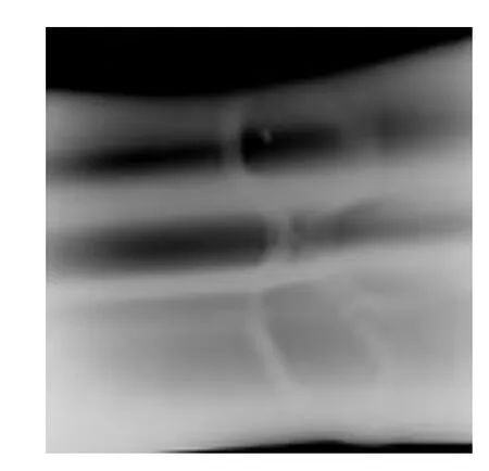
Fig.14.X ray imaging
5.4 Bulge Test
The major equipment for expansion pressure tests of EPLs is a special electric test pump which is shown by Fig.15,its model is 4DSY-15/80 with displacement of 15 L/h,outlet pressure of 80 MPa and stroke of 40 mm;model of pressure gauge is YTN-75 with range of 0–100 MPa.

Fig.15.Electric test pump
The expansion pressure test procedure is as follows.
(1)After NDT was qualified,two end closure plates were used to seal ends of the welded specimen by welding,preparing conditions for expansion pressure test.
(2)The test pump was connected with the bulge specimen of EPL,and overall test specimen was placed in the burst pit.Expansion pressure test was started.
(3)The pressure pump was opened,deformation of EPL was observed when the pump pressure was 1 MPa.
(4)Each pressure was maintained for 5 min when the pump pressure was 2 MPa,10 MPa,15 MPa,30 MPa.Then expansion of EPL was measured,measurement data was recorded as shown in Table 1.

Table 1.Measurement data of relationship between size of EPL and pressure
By the data in Table 1,it can be found that small diameter increases rapidly and large diameter increases slowly with pressure increase for 8-inch and 9-inch EPLs.When the pressure reaches 30 MPa,large diameter and small diameter values are close and the EPLs expand into round pipelines(see Fig.16).Bulge pressure 35 MPa is a critical point,and more bulge pressure will result in cracking of liner welds.Tests show that the welds of EPL can meet expansion requirement of oil cementing.Bulge pressure curve for the process from bulge to cracking of EPL is shown in Fig.17.
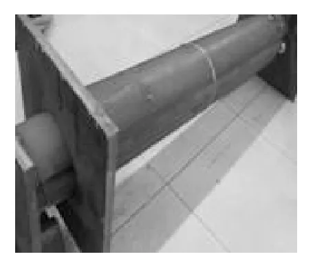
Fig.16.EPL appearance when pressure is 30 MPa

Fig.17.Bulge pressure graph of EPL
6 Conclusions
(1)A welding robot used to realize automatic welding of EPL is developed.The robot has the ability to move along the complex section seam of“8”type EPL smoothly.
(2)The small driven end actuator is designed to realize real-time detection of the angle in narrow space.A model of constant speed control for complex section welding with the robot has been built based on angle self-test.
(3)The cooperation work mechanism for the welding carriage and the small driven end actuator is established based on pressure detection.The problems of carrying and seam tracking of“8”type cross section of EPL for the welding robot are solved.
(4)By experimental verification,the developed welding robot of EPL can realize welding of 8-shaped complex trajectory weld with good weld appearance;there are no weld defects and weld quality is good.Expansion pressure tests show that the maximum pressure for the EPL reaches 35 MPa with good weld expansion roundness,that can meet the expansion requirements of oil well cementing.
[1]HAMOUDI I,KARTOBI K,VIEIRA P,et al.Application of solid expandable liners and managed pressure drilling in Algeria Nezla Field[C]//SPE/IADC Managed Pressure Drilling and Underbalanced Operations Conference and Exhibition,Milan,Italy,March 20–21,2012:1–11.
[2]ASIM Siddiqui,PATRICK York.Monobore solid expandable liners––Redesigning wells for a more economical and operational benefit[C]//International Petroleum Technology Conference,Bangkok,Thailand,February 7–9,2012:1–18.
[3]CLAUDIO Salute,ANTONIO Sardo,BRIAN Marr,et al.Unique combination openhole/cased hole solid expandable liner facilitates cost effective conversion of producer to gas storage well[C]//SPE Annual Technical Conference and Exhibition,Florence,Italy,September 19–22,2010:1–10.
[4]LI Juan.Application of expandable casing in drilling operation[J].West-China Exploration Engineering,2006,18(11):175–177.
[5]YANG Shunhui,HUANG Yonghong,TAO Xinghua.Theapplication of expandable convoluted tubing technique in Well Wei 15–19[J].Petroleum Drilling Techniques,2007,35(3):55–57.
[6]MIKE A Luke.Apparatus and methods of running an expandable liner:United States,US 2013/0228344 A1[P].2013-09-05.
[7]ALEJANDRO Berenstein,JOSEPH C Eder.Expandable body cavity liner device:United States,US 7695488 B2[P].2010-04-13.
[8]YANG Shunhui.Research of expandable casing used in drilling operation[D].Dongying:China Petroleum University,2008.
[9]TAO Xinghua,MA Kaihua,WU Bo,et al.Summary of expandable bellows field test and existing problem analysis[J].Petroleum Drilling Techniques,2007,35(4):63–66.
[10]TAO Xinghua,ZHU Hongwu,ZENG Yijin,et al.Development and mechanism motion analysis of welding robot for expandable profile liner[J].Journal of China University of Petroleum,2011,35(4):119–128.
[11]XU Yanling,LIN Tao,CHEN Shanben.Welding robot application status and development trend of research[J].Machinist Metal Forming,2010(8):32–36.
[12]JIANG Lipei,JIAO Xiangdong,XUE Long,et al.Flexible magnetic wheel type intelligent welding robot for spherical tank[J].ChineseJournal of Mechanical Engineering,2002,15(2):173–176.
[13]ZHANG Ke,LÜ Xueqin,WU Yixiong,et al.Algorithm and implementation of auto-searching weld line for welding mobile robot[J].Chinese Journal of Mechanical Engineering,2006,19(2):176–180.
[14]LI Junyue,LI Zhiyong,LI Huan et al.Basic theory and method of welding arc spectral information[J].Chinese Journal of Mechanical Engineering,2004,17(2):315–318.
[15]LIU Pengfei,SHAN Ping,LUO Zhen,et al.Detection method of spot welding based on multi-information fusion and fractal[J].Chinese Journal of Mechanical Engineering,2008,21(6):76–81.
[16]JIAO Xiangdong,YANG Yongyong,ZHOU Canfeng.Seam tracking technology for hyperbaric underwater welding[J].Chinese Journal of Mechanical Engineering,2009,22(2):265–269.
[17]LIU Yu,ZHAO Jing,LU Zhenyang,et al.Pose planning for the end-effector of robot in the welding of intersecting pipes[J].Chinese Journal of Mechanical Engineering,2011,24(2):264–270.
[18]HUO Liguo,BARON L.The joint-limits and singularity avoidance in robotic welding[J].Industrial Robot,2008,35(5):456–464.
[19]CHEN Zhixiang,LU Zhenyang,YIN Shuyan,et al.Models of weld pose and welding gun pose[J].Chinese Journal of Mechanical Engineering,2003,39(7):59–62.(in Chinese)
[20]WANG Xuanyin,DING Yuanming.Adaptive real-time predictive compensation control for 6-DOP serial arc welding manipulator[J].Chinese Journal of Mechanical Engineering,2009,23(3):361–366.
[21]WU Junfeng,CHEN Shanben,ZHANG Mingjun.Robust control of gas tungsten arc welding system[J].Chinese Journal of Mechanical Engineering,2007,20(5):32–36.
[22]DONG Chun,XU Wenli,YANG Geng.Method to improve dynamic tracking ability of spot welding manipulator with heavy payload[J].Chinese Journal of Mechanical Engineering,2004,17(3):433–436.
[23]JIAO Xiangdong,JIANG Lipei,XUE Long.Research on a welding robot of large vessel based on machine vision[J].Mechanical Science and Technology,2003,22(1):23–27.
[24]CAO Junfang,JIANG Lipei,SUN Yaling.Development of pipeline all-position welding robot mechanic system[J].Electric Welding Machine,2006,36(12):10–12.
[25]YAN Zheng,LIANG Junzhi,CHEN Jiang.PAW2000 pipeline all-position auto-welding machine[J].Electric Welding Machine.2005,35(6):47–53.
[26]ZOU Yong,JIANG Lipei,XUE Long.Study on welding robot for thick-walled pipeline[J].Electric Welding Machine,2009,39(5):90–92.
[27]PAN Jiluan,YAN Bingyi,GAO Lisheng.Crawl type all position arc welding robot[J].Electric Welding Machine,2005,35(6):1–5.
[28]XU Lili,XUE Long,TAO Xinghua.Design and motion simulation of automatic welding actuator for special-shaped pipeline welding robot[J].Electric Welding Machine,2011,41(5):5–9.
[29]SMARTT H B,LARSEN E D,PACE D P,et al.Design of a robotic welding system[C]//ASM Proceedings of the 7th International Conference:Trends in Welding Research,2005:623–627.
[30]SONG Mengmeng.Research of constant speed and tension control based on fuzzy PID control[D].Nanchang:Jiangxi University of Science and Technology,2010.
[31]WU Fei.Constant speed controlling system to diesel engine based on error compensating PID regulation[J].Agricultural Equipment &Vehicle Engineering,2010(5):52–53.
[32]ZHOU Liying,YUE Guoshu.Application of fuzzy-pid control algorithm in uniform velocity temperature control system of resistance furnace[J].Chinese Journal of Scientific Instrument,2008,29(2):405–409.
杂志排行

Chinese Journal of Mechanical Engineering的其它文章
- Mesoplasticity Approach to Studies of the Cutting Mechanism in Ultra-precision Machining
- Web Tension Regulation of Multispan Roll-to-Roll System using Integrated Active Dancer and Load Cells for Printed Electronics Applications
- Interactive Training Model of TRIZ for Mechanical Engineers in China
- Annoyance Rate Evaluation Method on Ride Comfort of Vehicle Suspension System
- Optimizing the Qusai-static Folding and Deploying of Thin-Walled Tube Flexure Hinges with Double Slots
- Experimental Study on Occupant’s Thermal Responses under the Non-uniform Conditions in Vehicle Cabin during the Heating Period