Investigation of CFD Calculation Method of a Centrifugal Pump with Unshrouded Impeller
2014-02-07WUDazhuanYANGShuaiXUBinjieLIUQiaolingWUPengandWANGLeqin
WU Dazhuan *,YANG Shuai XU BinjieLIU QiaolingWU Pengand WANG Leqin
1 Institute of Process Equipment,Zhejiang University,Hangzhou 310027,China
2 Engineering Research Center of High Pressure Process Equipment and Safety of Ministry of Education,Zhejiang University,Hangzhou 310027,China
1 Introduction*
Along with the development of computational fluid dynamics(CFD),three-dimensional(3D)numerical simulation has been widely applied in hydrodynamic performance prediction of centrifugal pumps.Performance and internal-flow predictions in pumps design can be adequately addressed using accurate and reliable CFD methods.In addition,numerical simulations have widely replaced the model tests,thus reducing the design cost and testing cycles in industrial applications.
Many researchers have conducted numerical simulation,including steady-state,unsteady,and transient simulations by modeling the entire flow passage of the internal flow in a centrifugal pump impeller.MUGGLI,et al[1],investigated the internal flow and performance of a mixed-flow pump from shut off to maximum flow using CFD calculation.JOSE,et al[2]performed numerical simulation of a centrifugal pump under various transient conditions,and studied the dynamic and unsteady flow effects of the impeller–volute interaction.WU,et al[3],simulated the unsteady 3D turbulent flow of a prototype Kaplan turbine by modeling the entire flow passage and predicted the pressure fluctuation at several survey points.SAFIKHANI,et al[4],calculated the efficiency and the required NPSH in a set of centrifugal pumps and then genetically optimized the geometrical parameters of the pumps.WU,et al[5],calculated the transient performance of a centrifugal pump during the discharge valve rapid opening process using CFD tools.WU,et al[6],employed the detached eddy simulation(DES)turbulent flow simulation in a centrifugal pump to examine and verify the particle image velocimetry(PIV)measurement results.LI,et al[7],investigated the influence of unsteady rotor–stator interaction on the film-cooling effect of the flow field surrounding the cooling holes of moving blades.ANDREAS,et al[8],studied the rotating stall phenomenon in a centrifugal pump,measured the stall frequency in the stationary frame using PIV,and analyzed the CFD data in the rotating frame.
As for different numerical simulation methods,the standard k–ε turbulence model is usually used for numerical calculations of the hydrodynamic performance of centrifugal pumps.Considering the complexity of flow in a pump,descriptions of the internal flow using turbulence model have a larger distortion compared with the actual values.The standard k–ε,renormalization group(RNG)k–ε,RSM,SST,and Spalart–Allmars(S–A)turbulence models have been employed by researchers,confirming the correspondence between the simulation and experimental results.Further,DES and large eddy simulation(LES)simulations were also used to simulate pump flow.JAFARZADEH,et al[9],proved that the result of the numerical simulation from the Realizable k–ε model best agreed with the experimental result.Further,TONG,et al[10],adopted the standard k–ε model and RSM for numerical simulation of a centrifugal pump.MAJUMDAR,et al[11],focused on an implicit pressure-based finite-volume algorithm for numerical solution of Reynolds averaged Navier–Stokes(RANS)equation in an inertial frame of reference to predict the unsteady incompressible-flow problems.This algorithm is applicable to pumps and other fluid machineries.
In addition,some researchers have investigated the flow in low-specific-speed centrifugal pumps and paid particular attention to the stability and efficiency of the pumps.JAFARZADEH,et al12],presented a general 3D simulation of turbulent flow in a centrifugal pump and analyzed the effect of the number of blades on the pump characteristics.PELEGRI,et al[13],studied the front leakage flow of a low-specific-speed multistage centrifugal pump to reduce recirculating flows and improve the overall efficiency.CHOI,et al[14],investigated the internal flow and hydrodynamic performance of a very low-specific-speed centrifugal pump.The results showed that large reverse flow at the open impeller outlet decreases considerably the absolute tangential velocity,which in turn decreases the pump head.PARK,et al[15],performed unsteady CFD simulations for a low-specific-speed centrifugal pump operating with and without balancing holes and having cut-away impeller sections.LI,et al[16],simulated turbulent flow in a semi-open centrifugal pump impeller.The pump performance was calculated and evaluated.SHUKLA,et al[17],analyzed the tip clearance flow of a semi-open impeller pump using 3D simulation.LI,et al[18],developed a stock-pump design based on numerical simulation of pulp fiber suspension in a pump.The simulation results were used to predict the pump performance and provide optimal basis.
However,relatively large errors were found in some CFD simulation results in some low-specific-speed centrifugal pumps with unshrouded impeller,which might have been influenced by special impeller structures in the pumps and the accuracy of the employed calculation model.In semi-open or unshrouded impeller,inverse flow often occurs in the impeller outlet because of the open-type impeller.In addition,the clearances and balance holes rotating with the impeller can influence the internal flow.In traditional calculation models,the semi-open or unshrouded impeller is often considered as a shrouded impeller,the front and rear clearances are not accurately modeled,or the effect of clearances is not considered.In particular,the outlet channel in some types of unshrouded impellers is very narrow,and the impeller back-out vane is cut to ensure that the flow in the passage is not blocked;thus,the fluid in the back-out vane is forced to rotate with the impeller.Calculation for the energy loss in this part plays a significant role in the precise prediction for such kind of pumps.Therefore,accurate modeling and prediction methods for unshrouded impeller pump have to be thoroughly considered.An appropriate model for unshrouded impeller can be proposed to improve prediction accuracy and reduce calculation deviation.
In this paper,a low-specific-speed centrifugal pump was used to research the modeling and performance prediction method of unshrouded impeller.The hydrodynamic performance of unshrouded impeller,which takes into consideration the clearances in the modeling,was calculated and compared with experimental results.To capture the vortex and inverse flow and to meet the requirements of accurate simulation,different turbulence models and modeling methods of calculating the internal flow were chosen,including the setting of rotating-region application at the interface.Based on these calculations,effective modeling and numerical simulation methods were proposed to predict the hydrodynamic performance of lowspecific-speed centrifugal pumps with unshrouded impeller.
2 Model Description and Simulation Methods
2.1 Model description
The primary specifications of the pump numerical model are summarized in Table 1.The model pump is a low-specific-speed centrifugal pump with unshrouded impeller.The unshrouded impeller and its 3D model contain five double-curvature cylindrical balance holes and back-out vanes,as shown in Fig.1.

Table 1.Specifications of the pump model
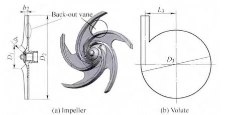
Fig.1.Schematic view and 3D model of unshrouded impeller
Two methods,namely,non-clearance simplified model and whole 3D model,are adopted to analyze the pump flow and hydrodynamic performance.The non-clearance model only contains the flow passages of the unshrouded impeller,volute diffuser,and the back-out vane without a lip between the impeller and the back wall.On the other hand,the whole 3D model includes the other flow passages of the balance holes and the front and rear clearances.Additionally,the back-out vane passage rotates with the impeller.Thus,volume and hydraulic losses of the centrifugal pump are taken into consideration more comprehensively in the whole 3D model.
The flow passage in the back-out vane reflects the main difference between semi-open and completely shrouded impellers.To analyze its influence on hydrodynamic performance prediction,the passage is primarily studied.The low-specific-speed-pump whole model is shown in Fig.2.Although the balance holes can reduce the axial force,bearing wear,and vibration in the pump,they nevertheless can introduce some volume losses.Therefore,they are included in the whole model to increase the accuracy of the numerical simulation.

Fig.2.Schematic cross section of 3D calculation model
2.2 Mesh description
Taking into consideration the handling of the rotating regions in the unshrouded impeller,two methods,namely,connected and disconnected methods,are employed to divide the model into several elements in the software GAMBIT.In the connected method,the node’s data are transferred by the interior face.The grid in the interface is conformal,and the continuity of the absolute velocity is enforced to provide correct neighboring velocity values at the near-interface zone.In the disconnected method,the grid in the interface can be non-conformal.The fluxes across the non-conformal grid interface are computed using the face that appears from the intersection of the two interface regions(Fluent 6.2 User’s Guide,2005).A final mesh with 3 895 357 cells defines the whole model.The wall y+is controlled to stay at less than 40 in all the models.The local mesh distribution in the pump,which corresponds to the non-clearance simplified model,is shown in Fig.3.Using twisting blades and complex clearance shape,tetrahedral meshes with high adaptive capability are used to generate high-quantity mesh in the model.The mesh density and the quality of the impeller are very important in accurately predicting hydrodynamic performance because they provide the advantage of rapid convergence and high precision.Therefore,simulation deviation can be reduced by choosing properly the grid to obtain relatively accurate performance curve.
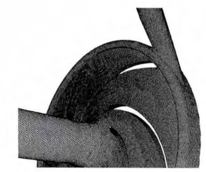
Fig.3.Detail of pump mesh
Grid-size dependence test is implemented using several grid spacing under a certain design condition with a flow rate of 18 m3/h.Table 2 shows that the power and efficiency of the non-clearance simplified model only change by 0.5% when the range of the grid number increases from-16% to+23% in models WM2 and WM3.

Table 2.Calculated results from different grids
When the grid number in model WM1 is at an average level and the maximal value of equally sized skew reaches 0.80,the hydrodynamic performance is nearer the design requirement with only a 0.84% pump head deviation.Investigations showed that the size of the resulting cells provides correct values and captures the present basic phenomenon.
2.3 Numerical scheme
The Fluent 6.2 code,a commercial finite-volume-based CFD code with a broad range of computational capabilities,is used in the present study.The pump is simplified as a calculated 3D incompressible steady flow problem with fully developed turbulence.The fluid zone in the impeller region is modeled as a rotating frame of reference,and the surrounding zones are modeled as stationary frame using multiple reference frames(MRFs).The time-dependent term is a first-order implicit scheme.The pressure–velocity coupling is calculated using the SIMPLE algorithm.The second-order upwind scheme with numerical underrelaxation is applied for the discretization of the convection term,whereas the central difference scheme is applied for the discretization of the diffusion terms.Calculations are performed using a Linux PC cluster of eight Intel Xeon processors(3.2 GHz).
The boundary conditions include the velocity inlet,pressure outlet,wall boundary,and interface.The velocity inlet defines the relative scalar fluid velocity and flow properties.The inlet velocity,turbulence intensity,and hydrodynamic diameter are used based on operating conditions.The outlet pressure is specified by a fixed static pressure of 6 MPa because the set under cavitation-free condition does not affect the simulation results;the flow near the wall is described by a standard wall function.
3 Influence of Rotary Region
3.1 Influence of back-out vane passage
As the rotary region of a shrouded impeller is defined by the MRF coordinate system,the flow passage in the shrouded blades from the impeller inlet to the outlet is set as a rotary region.This configuration is appropriate for normal specific-speed pumps.However,in the centrifugal pump model used in this paper,the rotary region includes not only the blades in the impeller but also the balance holes and the back-out vane region.The fluid in the back-out vane belongs outside the impeller work area and totally rotates with the impeller.In addition,the clearance and balance holes affect the hydraulic and volume losses.
The non-clearance model is used to analyze the modeling and the rotary-region handling of the flow passage in the unshrouded impeller.In particular,the back-out vane passage is a special structure of the model that is different from the semi-open or shrouded impeller.Taking into consideration the back-out vane region can introduce an obvious effect on the numerical accuracy.Thus,three different non-clearance models,namely,model WN1 with rotating back-out vane region,model WN2 with stationery back-out vane region,and model WN3 without a back-out vane region,are developed.
Table 3 presents the description of the three models.The calculation models comprise the inlet tube,impeller,and volute diffuser;the front and rear clearances of the impeller are ignored.The grid number is 1 692 064,and the maximal skew value of the mesh is 0.85.Based on the 3D flow simulation of the pump,the hydrodynamic performances under five operating conditions,namely,0,6,12,18,and 25 m3/h,are calculated and shown in Fig.4.The numerical results from the different models are compared with the experimental results obtained from a performance test conducted in a standard test facility.
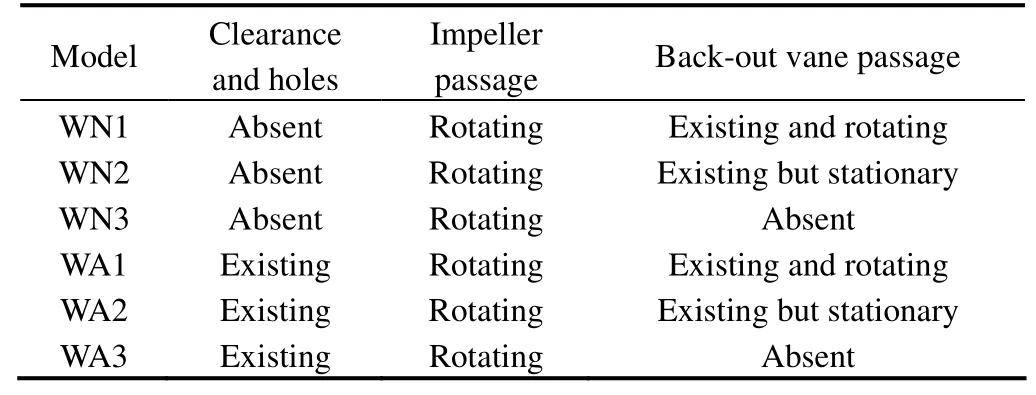
Table 3.Difference in calculation models

Fig.4.Performance of the non-clearance models
From the comparison of the performance curves,model WN1 shows a large deviation from the experimental results.The power is lower,but the efficiency and the head are higher.The deviation of the head under operating condition of 18 m3/h is 23.5%.This tendency is caused by the overestimated energy of the back-out vane passage in the WN1 model where the back-out vane passage is considered as one part of the unshrouded impeller.The numerical head of model WN2 is 29.45% lower than that of the experimental results.This condition shows that the assumption that the back-out vane passage is stationary affected the flow structure of the impeller in the WN2 model.The results of model WN3 are closer to those of the experiment,and the deviation of the head under the same operating condition is only 3.8%,indicating that neglecting the back-out vane passage in the non-clearance model is advantageous in improving the simulation accuracy of the unshrouded impeller.The deviation between the numerical and experimental results of the WN3 model is mainly attributed to the exclusion clearance and balance hole leakages.According to the results of the WN1,WN2,and WN3 models,taking into consideration the back-out vane passage obviously affects the performance prediction accuracy of the unshrouded impeller.As the back-out vane passage is not directly radially connected to the entrance and forms a separate area at the impeller outlet,the fluid in the back-out vane passage does not contribute to the total head rise of the pump nor does it affect the main flow in the pump impeller.However,the existence of the back-out vane passage can reduce disk friction loss of the low-specific-speed impeller.
To further analyse the mechanism of these phenomena,the vorticity distributions of the three models are shown in Fig.5.Fewer vorticities are found in the WN1 model compared with those in the WN2 and WN3 models,indicating that the rotary back-out vane passage improves the simulated flow condition relative to the actual situation,and the improvement of the flow structure leads to overestimated pump head.With stationary back-out vane passage in the WN2 model,the simulated vorticity in the impeller passage obviously increases,causes large flow losses,and underestimates the head.The simulated flow structure is also affected by the assumption of stationary back-out vane passage.When the simulation does not take into account the influence of the back-out vane passage,the simulated head of model WN3 is closer to that of the experiment,but the deviation of the simulated power and efficiency are higher.Hence,for better performance prediction of the unshrouded impeller,calculation accuracy can be effectively improved by neglecting the back-out vane passage in the model,and building a more suitable simulation model becomes necessary.
3.2 Influence of the clearance and balance holes
To analyze the influence of clearance and balance holes on the pump performance calculation accuracy,three whole models,including clearance and balance holes,are investigated.Similar to the non-clearance models,the whole models include model WA1 with rotating back-out vane region,model WA2 with stationery back-out vane region,and model WA3 without back-out vane region.The description of the three models is shown in Table 3.In addition,the front and rear clearances are regarded as stationary fluid region,and the balance holes are treated as an impeller rotating region.The numerical simulation results are shown in Fig.6 and compared with the experimental results.
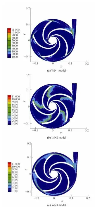
Fig.5.Vorticity distribution in different non-clearance models(s–1)
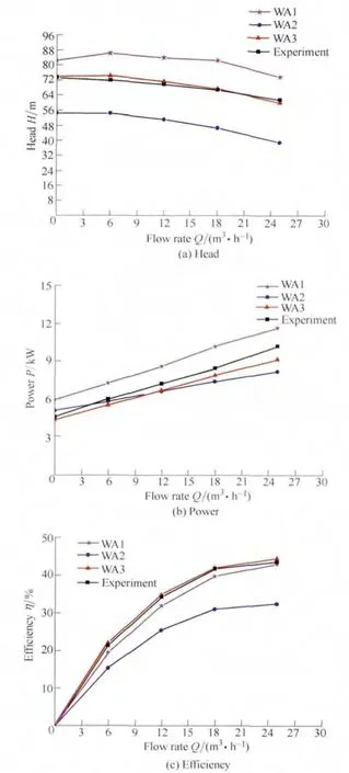
Fig.6.Performance of the whole model
Fig.6 shows that the head,power,and efficiency of models WA1 and WA2 largely differ from the experimental values.With the existence of the clearance passage,the power of model WA1 is larger than that of the experiment.Model WA3 shows better agreement than the other models.Similar to the non-clearance models,the rotating back-out vane passage in the whole model also results in overestimated head of the prediction performance.Further,the assumption of stationary back-out vane passage in the whole model affects the flow structure of the simulation.Ignoring the back-out vane passage is also advantageous in improving the simulation accuracy of the whole model of unshrouded impeller.
Fig.7 shows the prediction performance curves of the WN3 and WA3 models,which are compared with the experimental results.The influence of the clearance and balance holes can be discerned from the figure.The efficiency error reaches up to 40% in the non-clearance WN3 model,mainly due to the absence of significant volume and mechanical losses in the clearance of the low-specific-speed pump.Under the flow-rate operating condition from 0 m3/h to 25 m3/h,the calculation results from the WA3 model are very close to the experimental results,and the efficiency error is only 0.59% at the design point under a flow-rate of 18 m3/h.Hence,the front clearance,rear clearance,and balance holes should be included in the calculation model of the unshrouded impeller of low-specific-speed pumps.
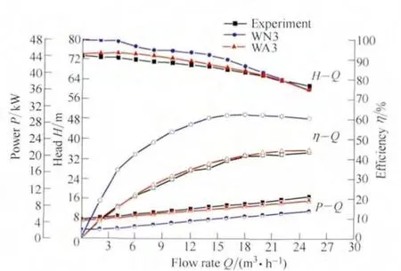
Fig.7.Performance of the WN3 and WA3 mode
Fig.8 shows that the vorticity at the entrance of the WA3 whole model,taking into account the clearance and balance holes,is larger due to the influence of the clearance passage,which leads to the decline in the performance.However,relative to the volute tongue,the vorticity coverage in the WN3 non-clearance model is wider than the whole model,possibly due to the more serious flow separation in the impeller outlet with higher velocity.
4 Influence of Numerical Methods
4.1 Interface handling
The clearance thickness in the whole model of unshrouded impeller is not more than 0.5 mm.Its geometric scale is much smaller than the pump impeller and the volute.Interface is employed to separate the impeller and volute passages to generate sufficiently fine grid in the clearance region and relatively thicker grid in other regions.Two methods,namely connect and disconnect interfaces,are used to deal with the data transfer between two regions.In the connect interface,the grid nodes in the clearance correspond to the impeller,and the grid size is regulated adaptively using tetrahedral mesh.In this situation,the desirability of boundary mesh should be checked.The WA3 model is calculated using this method.In the disconnect interface,the grid size in the clearance does not need to be consistent with the impeller,which uses interface to transfer surface pressure and velocity vector.The interface described by the MRF coordinate is mainly used to associate the faces between the stationary and rotating regions.The overlap at the transition is used as default interior face,and the non-overlapping area is considered as default wall.
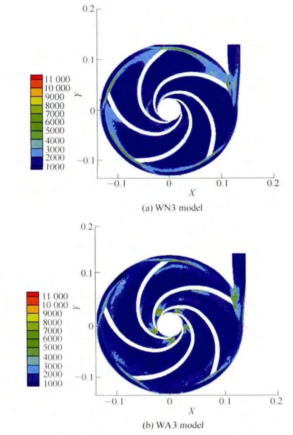
Fig.8.Vorticity distribution in the WN3 and WA3 models(s–1)
Five different operating conditions with flow rates of 0,6,12,18,and 25 m3/h are simulated to analyze the influence of data transition,and the operating rotational speed of the pump is 2900 r/min.The comparative results under the five operating conditions are shown in Fig.9.

Fig.9.Performance of the WA3 with interface model
Fig.9 shows that the results of the disconnect interface model at the rated flow rate of 18 m3/h is basically the same as that of the connect interface WA3 model.However,the simulation results are lower than the experimental results under low flow-rate conditions.In addition,the predicted head and efficiency of the interface model are lower than the experimental values under the 25 m3/h flow-rate condition.The deviation may be caused by numerical dissipation during the interface simulation because the pressure and velocity transitions in the interface are realized using the average interpolation method,and some small-scale vortices and energy losses are ignored during the data transfer.
The internal flow and vorticity at the front clearance section under the rated flow-rate of 18 m3/h is shown in Fig.10,which shows that the vorticity magnitude in the disconnect interface between the impeller and the front clearance is higher than the reasonable value.Moreover,the high vorticity magnitude region of the back-out vane passage in the disconnect interface model is very narrow.The flow structure in the near-interface region is not accurately predicted by the disconnect interface model,increasing the deviation between the numerical and experimental results.
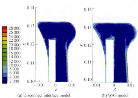
Fig.10.Vorticity distribution of the different models(s–1)
4.2 Turbulence model selection
To analyze the applicability of the turbulence models for 3D flow simulation in unshrouded impeller,four different turbulence models:standard k–ε,RNG k–ε,Realizable k–ε,and S–A,are used in the WA3 model.The standard k–ε model is established for fully developed turbulent flow with high Reynolds number,mainly based on the turbulent kinetic energy and the diffusion rate.The RNG k–ε model considers turbulent eddies,which better deals with high strain rate and large curvature flow.However,analysis of low-Reynolds-number flow viscosity should still be resolved using the wall function.The Realizable k–ε model has a good accuracy in the rotating flow,boundary-layer flow with strong adverse pressure gradient,flow separation,and secondary flow.In addition,it can improve the accuracy of the low Reynolds number simulation.Its weakness is that it cannot provide natural turbulent viscosity of the flow region in the calculation of rotating and stationary regions.The S–A model is very effective for low-Reynolds-number model,and the variable gradient near the wall is much smaller than that in the k–ε and k–ω models,thus less sensitive to numerical errors.
Fig.11 shows that the four turbulence models can perfectly simulate the main internal flow characteristics of low-specific-speed centrifugal pumps with shrouded impeller and can obtain accurate hydrodynamic performance.From the analysis of the flow-rate head curves,the head predicted by the standard k–ε and RNG k–ε models is close to the experimental value at zero flow rate.However,at the flow-rate operating condition of 6 m3/h,the predicted value is higher,which causes a hump feature on the performance curve.The reason for this phenomenon is that laminar flow with low Reynolds number near the wall is difficult to predict accurately at low flow rate.Although the S–A turbulence model is close to the experimental results at flow rates of 12 m3/h and 18 m3/h,the head deviation increases at a flow rate of 6 m3/h,indicating that pump performance at low flow-rate cannot be well predicted by this model.
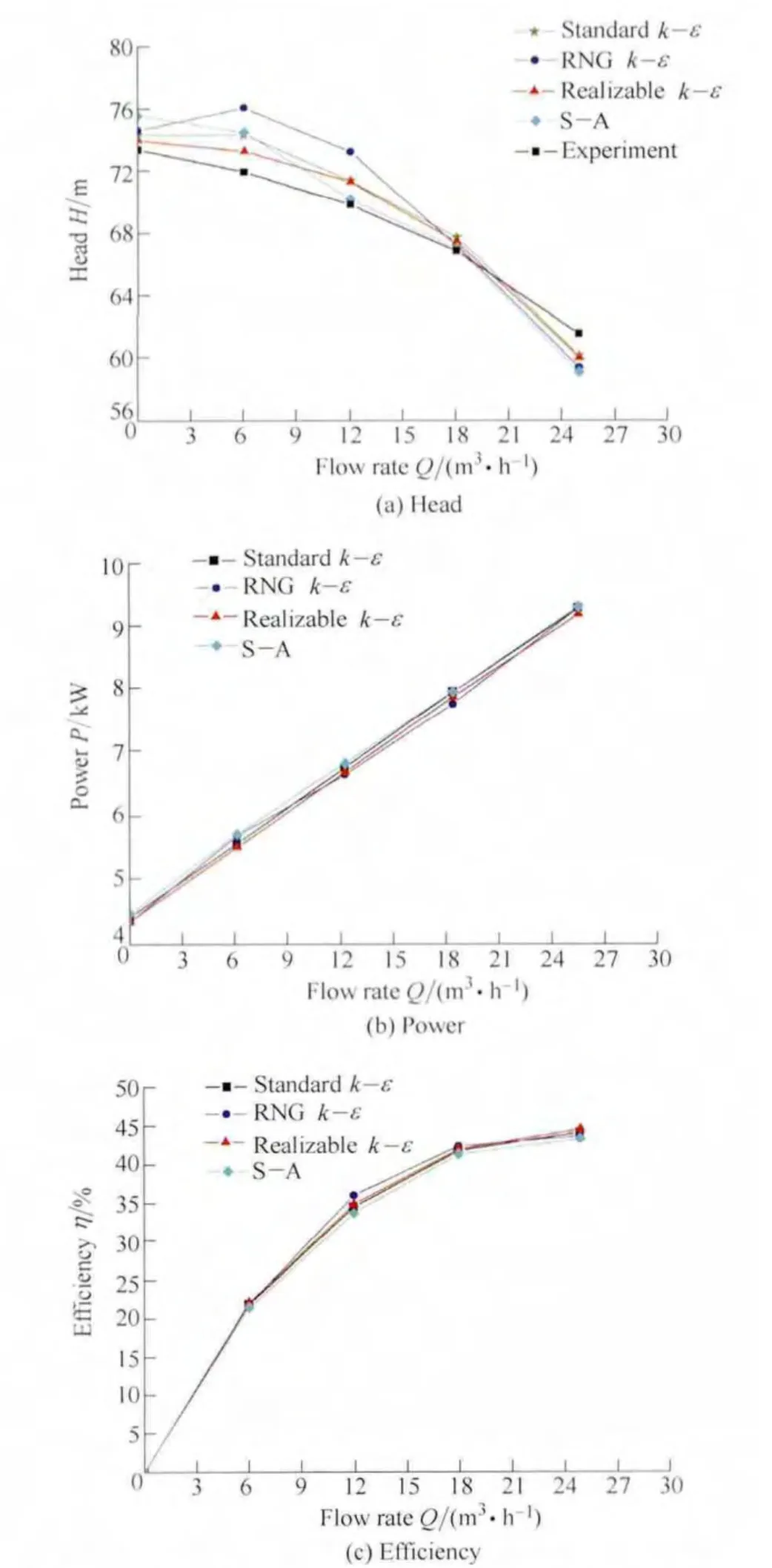
Fig.11.Performance of the different turbulence models
Compared with the previous three models,the prediction results based on Realizable k–ε model are closest to the experimental results under all operating conditions.Relative to the convergence rate,the iteration steps of the Realizable k–ε,S–A,RNG k–ε,and standard k–ε models are 4000,3500,5000,and 5000,respectively.The iteration time of the Realizable k–ε model is slightly higher than that of the S–A model but lower than that of the other two models.Furthermore,from the pressure value monitored at the inlet and outlet of the pump,the static pressure of the Realizable k–ε model is more stable during convergence.Thus,for the turbulence model of a low-specific-speed centrifugal pump with unshrouded impeller,the Realizable k–ε model is the best applicable model.
5 Conclusions
(1)In consideration of the back-out vane passage significantly affecting the prediction accuracy of the unshrouded impeller performance in the simulation,properly handling the clearance and choosing the appropriate turbulence model are beneficial in improving the numerical accuracy of low-specific-speed pump.
(2)As the back-out vane passage is not radially connected directly to the entrance and forms a separate area in the outlet of the unshrouded impeller,the fluid in the back-out vane passage does not contribute to the total head rise of pump nor affects the main flow in the pump impeller.The rotary region approach that considers the back-out vane passage will cause an overestimated pump head.On the contrary,assuming that this area is stationary will result in an underestimated pump performance.Ignoring the back-out vane passage is useful in improving the simulation accuracy of unshrouded impeller performance.
(3)Volume and mechanical losses are significant for the clearance of low-specific-speed pumps.The front clearance,rear clearance,and balance holes should be included in the calculation model of low-specific-speed pumps with unshrouded impeller.
(4)The disconnect interface can help generate sufficiently fine grid in the clearance region,and the predicted results agree well with the experimental results at the designed operating point.However,relatively large deviation between numerical and experimental results is found at the off-design operating point.The Realizable k–ε model is the most suitable model for 3D flow simulation of the unshrouded impeller.
(5)The numerical error is relatively large at very low flow-rate operating condition due to the limitations in the turbulence models and the grid scale.Further studies should be conducted for comparisons with the RANS,LES,and DES simulation of low-specific-speed pumps with unshrouded impeller.Moreover,experimental flow test techniques,such as the PIV,are ideal in investigating the flow in back-out vane passage.
[1]MUGGLI F A,HOLBEIN P,DUPONT P.CFD calculation of a mixed flow pump characteristic from shut-off to maximum flow[J].Journal of Fluids Engineering-Transactions of the ASME,2002,124(3):798–802.
[2]JOSÉ G,JOAQUÍN F,EDUARDO B,et al.Numerical simulation of the dynamic effects due to impeller-volute interaction in a centrifugal pump[J].Journal of Fluids Engineering-Transactions of the ASME,2002,124(2):348–355.
[3]WU Yulin,LIU Shuhong,DOU Huashu,et al.Numerical prediction and similarity study of pressure fluctuation in a prototype Kaplan turbine and the model turbine[J].Computers &Fluids,2012,56:128–142.
[4]SAFIKHANI H,KHALKHALI A,FARAJPOOR M.Pareto based multi-objective optimization of centrifugal pumps using CFD neural networks and genetic algorithms[J].Engineering Applications of Computational Fluid Mechanics,2011,5(1):37–48.
[5]WU Dazhuan,WU Peng,LI Zhifeng,et al.The transient flow in a centrifugal pump during the discharge valve rapid opening process[J].Nuclear Engineering and Design,2010,240(12):4061–4068.
[6]WU Yulin,LIU Shuhong,YUAN Huijing,et al.PIV measurement on internal instantaneous flows of a centrifugal pump[J].Science China-Technological Sciences,2011,54(2):270–276.
[7]LI Zhou,HONG Zhoufan,XIN Zhang,et al.Investigation of effect of unsteady interaction on turbine blade film cooling[J].Engineering Applications of Computational Fluid Mechanics,2011,5(4):487–498.
[8]ANDREAS L,GUNTHER B.Numerical simulation and evaluation of velocity fluctuations during rotating stall of a centrifugal pump[J].Journal of Fluids Engineering-Transactions of the ASME,2011,133(8):1–8.
[9]JAFARZADEH B,MOKHTARPOOR R,ALISHAHI M M.Investigation of turbulence modeling in a high speed centrifugal pump with an inducer[C]//2007ASME International Mechanical Engineering Congress and Exposition,Seattle,USA,November 11–15,2007:333–338.
[10]TONG Yueping,ZHANG Shujia,LI Xianhua,et al.Application and comparison of the standard κ-ε model and the RSM on numerical simulation of centrifugal pump[J].Journal of Zhejiang University of Technology,2008,36(6):678–681.
[11]MAJUMDAR S,RAJANI B N,KULKARNI D S,et al.Numerical simulation of incompressible turbulent flow using linear eddy viscosity-based turbulence models[J].Defence Science Journal,2010,60(6):614–627.
[12]JAFARZADEH B,HAJARI A,ALISHAHI M M,et al.The flow simulation of a low-specific-speed high-speed centrifugal pump[J].Appiled Mathematical Modeling,2011,35(1):242–249.
[13]PELEGRI M,ARMENGOL J,GONZALEZ J R.et al.Evaluation of the front leakage flow in a low-specific-speed centrifugal pump[M]//Environmental Hydraulics-Theoretical,Experimentaland Computational Solutions.CRC Press,2009:273–275.
[14]CHOI Y D,KUROKAWA J,MATSUI J.Performance and internal flow characteristics of a very low specific speed centrifugal pump[J].Journal of Fluids Engineering-Transactions of the ASME,2006,128(2):341–349.
[15]PARK S H,MORRISON G L.Centrifugal pump pressure pulsation prediction accuracy dependence upon CFD models and boundary conditions[C]//Proceedings of the ASME 2009 Fluids Engineering Division Summer Meeting,Colorado,USA,August 2–6,2009:207–220.
[16]LI Haifeng,MU Zhongbo,WU Yulin.Numerical simulation of the 3D turbulent flow in a semi-open centrifugal pump impeller[J].Pump Technology,2011(1):9–15.
[17]SHUKLA SN,KSHIRSAGAR J.Numerical simulation of tip clearance flow in semi-open impeller pump[C]//5th Joint ASME/JSME Fluids Engineering Summer Conference,California,USA,July 30–Aug 2,2007:821–830.
[18]LI Hong,YUAN Shouqi,YUAN Jianping,et al.Stock pump design based on numerical simulation of pulp fiber suspension in pump[J].Journal of Jiangsu University(Natural Science Edition),2007(1):51–55.
杂志排行

Chinese Journal of Mechanical Engineering的其它文章
- Intelligent Identification of Wear Mechanism via On-line Ferrograph Images
- Experimental Model and Analytic Solution for Real-time Observation of Vehicle’s Additional Steer Angle
- Experimental Study on Occupant’s Thermal Responses under the Non-uniform Conditions in Vehicle Cabin during the Heating Period
- Optimizing the Qusai-static Folding and Deploying of Thin-Walled Tube Flexure Hinges with Double Slots
- Annoyance Rate Evaluation Method on Ride Comfort of Vehicle Suspension System
- Constant Speed Control for Complex Cross-section Welding Using Robot Based on Angle Self-Test