Optimizing the Qusai-static Folding and Deploying of Thin-Walled Tube Flexure Hinges with Double Slots
2014-02-07YANGHuiDENGZongquanLIURongqiangWANGYanandGUOHongwei
YANG Hui,DENG Zongquan,LIU Rongqiang,WANG Yan,and GUO Hongwei*
State Key Laboratory of Robotics and System,Harbin Institute of Technology,Harbin 150080,China
1 Introduction*
The deployment mechanisms for numerous systems on satellites,such as synthetic aperture radars(SARs),solar arrays and booms,must be packed into compact volume for launching and also be able to spread to the operational configuration.The ordinary stowage and deployable apparatuses always use standard pin-jointed hinges to realize connection,which have moving parts and are sensitive to the friction.The stored strain energy deployable structures can be folded elastically and deployed by releasing the strain energy.Thus they have several key attractions for space applications which include lower cost,lightness,and friction insensitiveness.Besides,the stored strain energy deployable structures,like the tape spring hinges,the integral hinge,and the thin-walled tube flexure hinges with slots could be latched elastically by themselves.Therefore,these structures arouse numerous interests in research.It is well known that the TWTF hinges have been used in the Mars Advanced Radar for Subsurface and Ionosphere Sounding(MARSIS)[1].
To better comprehend the folding and deploying characters of tape spring hinges,relevant researches have been accomplished by using different analytical,numerical and experimental methods.MANSFIELD investigated that the tape spring like structures had the property of snap-through flexural buckling[2].SEFFEN,et al[3–5],investigated the deployment dynamics of the tape-spring hinge by the moment-rotation relationship.YEE,et al[6],discussed the relationship between longitudinal radius of the elastic folding scope and the transverse radius of the tape spring cross section for the composite tape springs.SILVER[7]analyzed the effects of shell geometry on tape-spring developed strength performance based on the Donnel-Mushtari-Vlasov shell theory for symmetric laminates.To improve the bending stiffness in the deployed allocation and the folding moment,several tape-springs were arranged in an offset or symmetric configuration by WARREN,et al[8]and BOESCH,et al[9].LANE,et al[10],tested one deployable structures of low-Earth-orbiting flight demonstration system which is connected by composite tape-spring hinges.To understand the impact of folding the tape-spring in three dimensions,WALKER,et al[11–12],studied the static moments by analytical methods and the development dynamics by experiments.KWOK[13]focused his study on the time and temperature dependent property stemming from the viscoelasticity and reciprocity with the geometrically response of the thin-walled structures.
The Integral hinges can be more stable with the entire structures under elastic deforming.These structures include the storable tubular extendible member(STEM)[14],the extendable boom consisted by joining two omega-shaped thin metal shells at the longitudinal edges[15],folding large antenna tape spring(FLAT)[16–17],and the hollow solid reflector structures[18]as shown in Fig.1.Though,a better stiffness,thermal properties and simpler fabrication are important for some applications.The TWTF hinges with two or three parallel longitudinal slots can meet those needs,which were proposed by MARKS and investigated the deployed dynamics of the mars advanced radar for subsurface and ionosphere sounding(MARSIS)by MOBREM,et al[19–23].MALLIKARACHCHI,et al[24–25],carried out a study on the quasi-static folding and deploying of the composite TWTF hinges by numerical and experiment methods,and optimized the slot geometry on the folding maximum strain.However,the previous optimization studies may miss some optimal results since they just change the geometry parameters at regular intervals.Moreover,the post-buckling behavior of the TWTF hinges folding and deploying involves high nonlinearities of geometry and material.The surrogate model techniques are often used in the nonlinear finite element analysis for fast iteration.Thus,considering the computational burden caused by the large range of design varies and optimization efficiency,the response surface method(RSM)is employed to derive the surrogate model for the TWTF hinges.
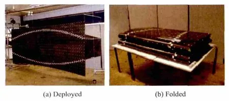
Fig.1.Hollow solid reflector
The purpose of this study is to optimize the quasi-static folding and deploying behaviors of the TWTF hinge with double slots as shown in Fig.2.The maximum peak moment of folding and deploying as well as minimum mass of the TWTF hinge are set as objectives.The slots length and the slots width are considered as the design variables,while the maximum Mises stress is set not to exceed the allowable stress.The RSM is employed to construct the functions of peak moment and maximum Mises stress.Beside this,parameter studies are performed to investigate the effect of the slots length and the slots width on the quasi-static folding and deploying performances of the TWTF hinges.The 25 samples design points are analyzed by ABAQUS/Explicit solver,which are used to derive the response surface functions.The multidisciplinary optimization software ISIGHT is employed to perform the multi-objective optimization.
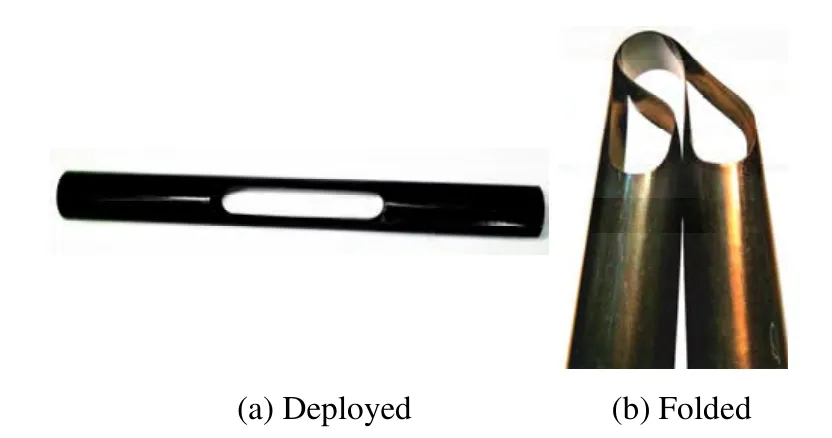
Fig.2.Thin-walled tube flexure hinge
2 Problem Description
The hinges considered in this study are TWTF hinges with double symmetric slots,and the slots width is equal to the end semicircle diameter.Meanwhile,the aim is to find the optimal slots parameters of the TWTF hinges to provide higher peak moment during folding and deploying as well as lower mass.The slot length and the slot width are chosen as two design variables,while the hinge total length and the end-section diameter are set as constants,the basic configuration is shown in Fig.3.

Fig.3.Dimensions of the TWTF hinge
When antennae work,the hinges should have enough bending stiffness to resist any shock.Take into account the cost of launch,the antennae mass is also limited.Thus,the peak moment of folding(Mf)and deployment(Md),and the mass are set as the multi-objectives in this study.The Mfand Mdshould be maximized,but the mass should be minimized.The two design parameters l and w couldn’t beyond the upper bound and the lower bound.What’s more,the maximum stress(Smax)is chosen as the constraint.Therefore,the optimization problem modeled is as follows:
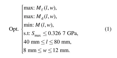
The RSM is employed to create the surrogate models for the optimal design objectives and design constraint in the later sections.
3 Response Surface Methodology(RSM)
Response surface methodology,as presented by BOX and WILSON[26],is a collection of mathematical and statistical techniques,and is widely applied in the optimization problem and processes developing[27–31].To get the optimal folding and deploying behaviors of TWTF hinges with double slots and reduce the computational cost,the surrogate models are modeled by RSM.
In the study,the responses of the TWTF hinges with double slots are Mf,Mdand Smax,which can be written in terms of a series basic function as

is the responses of Mf,Mdand Smax,N is the number of the basic functionsφi(l,w),βiis the coefficients of the basic functions,εis the error between the RS approximation at the point and the response yifrom FEA results.To ensure precision,the quartic polynomials of basic functions are chosen,so the responses can be written as follows:

The regression coefficients of quartic polynomials can be calculated by using the least-square method,which is
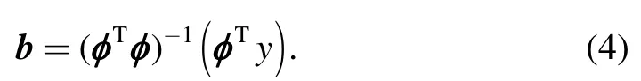
Where coefficient b=(β1,β2,…,βn),matrixφis
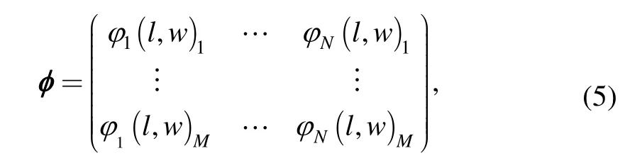
where M is the design points number.By substituting the Eq.(5)into Eq.(4),coefficient b can be determined.
The accuracy of the responses should be evaluated by some criteria,such as relative error(RE),the coefficient of multiple determination(R2),the root mean square error(RMSE),and the adjusted coefficient of multiple determinationrespectively,as follows:

where yiis the FEA results,SSTrepresents the total sum of squares,and SSErepresents the sum of squares of the residuals,respectively,as follows:

For the RS model,the values of R2andvary from 0 to 1,which mean the level of correlation between FEA results and the responses,thus the bigger the values ofand the smaller the values of REand RMSE,the better the fitness[32].
4 Design Optimization
4.1 Design of experiment(DOE)
For the purpose of deriving the function of Mf,Mdand Smax,finite element analyses(FEA)should be performed for a series of design points determined by design of experiment(DOE)within the design domain.There are some available DOE methods,such as orthogonal arrays,central composite design,Latin hypercube,full factorial,etc[33].The five-level full factorial design is employed in the following study,the slots length is changed from 40 mm to 80 mm by every 10 mm,and the slots width is changed from 8 mm to 12 mm by every 1 mm as shown in Table 1,which resulted in 5×5 sampling design points evenly distributed within the design ranges.Then,the coefficients of polynomial βiare calculated from the FEA results by using Eq.(4)and Eq.(5).
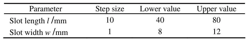
Table 1.Step size and range of design variables of TWTF hinge with double slots
4.2 Finite element modeling
The material of TWTF hinges with double slots is titanium-nickel alloy Ni36CrTiAl with mass density ρ=8.0×10³kg/m3,Young’s modulus E=20 GPa,Poisson’s ratio ν=0.35,yield stress σy=0.98 GPa,Ultimate stress σu=1.194 GPa.The total length of TWTF hinges is fixed as 180 mm,and the end-section diameter D is 19.5 mm and the thickness t is 0.12 mm.Both the folding time and deployment time of TWTF hinges are set as 1s.
As mentioned before,the FE models are set up in the ABAQUS/Explicit with four nodes fully reduced integrated shell elements(S4R)with element size 1.8 mm.To simulate the quasi-static folding and deploying of TWIF hinges,the end rotation two reference nodes 1 and 2 are located on each end and set as kinematic coupling constraint to either end surface.Node 1 is restrained all of the freedom except the rotation about the global y-axis,and node 2 is allowed to rotate about the y-axis as well as translate along the global z-axis.The bending angle α of the hinge is the sum of the rotational angle of the two reference nodes.To prevent damage,a small equal and opposite pinching load is applied to the middle of hinges before rotating to 170°as plotted in Fig.4.The little pinching load will be released during deployment step.In order to apply loads as smoothly as possible,the Smooth-Step is employed to apply and remove loads.To analyze the contact among the surfaces of TWTF hinge,the general contact is assigned to the whole model.
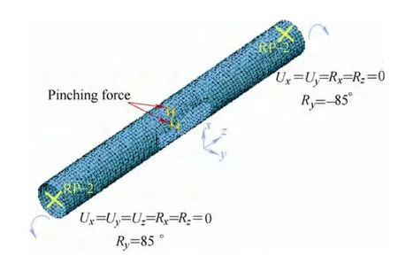
Fig.4.Finite element model for TWTF hinge with double slots
The deformation modes of the TWTF hinges with two typical deform configurations under a von Mises stress on different bending angle α can be depicted in Fig.5,the quasi-static deployment of the TWTF hinges is similar to the inverse process of folding.The FEA results of 25 design points are listed in Table 2.

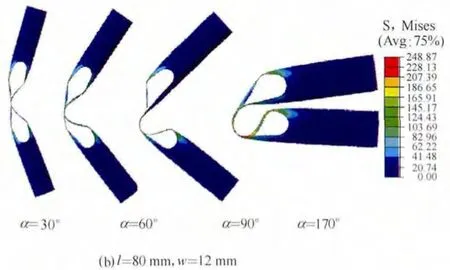
Fig.5.Two typical deformed configuration of TWTF hinges under a von Mises stress
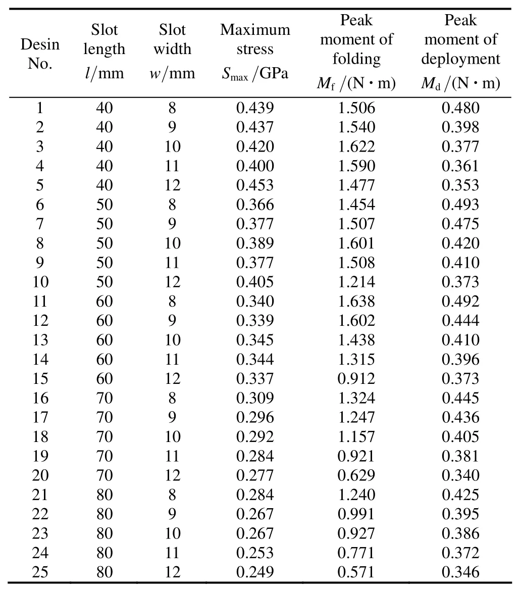
Table 2.FEA results for the selected 25 design points
4.3 Response surface method
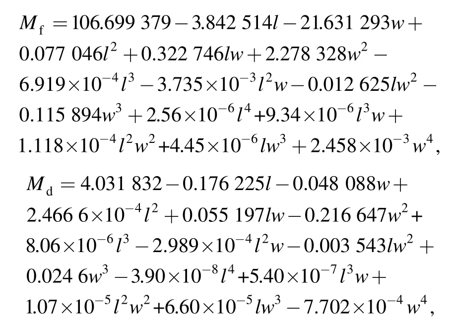
After getting the sample points of the quasi-static folding and deploying,the responses surface models for the TWTF hinges then can be derived by Eqs.(4)and(5)based on the simulation results in Table 2.So the quartic response polynomial functions of Mf,Mdand Smaxare derived as follows:

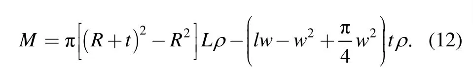
According to Fig.3,mass of the TWTF hinge(M)with double slots can be calculated by
According to Eqs.(6)–(11)based on section 3,the total errors between response surface model and FEA analysis are derived.The RMSE,R2and R2adjfor maximum stress are RMSE=0.006 016,R2=0.996 157,R2adj=0.991 615,Mfare RMSE=0.061 211,R2=0.985 659,R2adj=0.968 710 and Mdare RMSE=0.008 806,R2=0.982 983,R2adj=0.962 871.
The values of R2andare much closed to 1,and the RMSEis small enough to evaluate the precise of the RS model.Hence,the regression models of the 25 design points are validated to be accurate for this study.The response surface of Mf,Mdand Smaxis plotted the slots length and slots width in Fig.6.
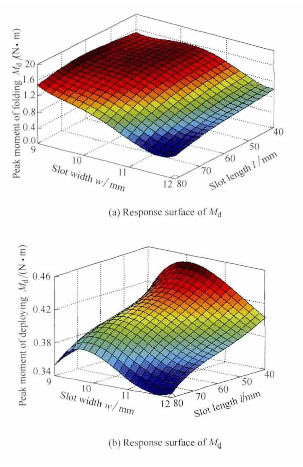
Fig.6.Response surface of Mf,Mdand Smax
The modified Non-Dominated Sorting Genetic Algorithm(NSGA-Ⅱ)is employed for the multi-objectives optimization.The population size and the generation are set to 48 and 50 respectively.The feasible designs of the optimization are depicted in Table 3,the indexes of Mdand Smaxis dominated,so the optimal design is selected as No.6,i.e.the slots length is 65.611 mm and the slots width is 9.873 mm.In this configuration,the maximum stress is lower and the peak moment is greater.So the deploying capacity of TWTF hinge is better and the stress distribution is smoother.Meanwhile,the numerical simulation of the optimal design is performed by ABAQUS/Explicit to ensure the correctness.The relative errors between the FEA results and optimal design of Md,Mfand Smaxare less than 7% which could be calculated from Table 4.
Table 3.Feasible designs of the TWTF hinge folding and deploying behaviors
Table 4.Relative errors between the FEA results and optimal design
5 Parametric Studies
Influences of the thin-walled hinges slots length l and slots width w on Mf,Mdand Smaxare investigated in this section based on Table 2.The baseline hinge geometry is used for the parametric study with D=19.5 mm,L=180 mm and t=0.12 mm.The slots width w equals to the slots end semicircle diameter ranging from 8 mm to 12 mm,and the slots length l ranging from 40 mm to 80 mm.Therefore,it is possible to reveal the effects of the design parameters l and w on the TWTF hinges quasi-static folding and deploying behaviors from Fig.7–Fig.9.
Fig.7.Variation of Mfwith slots length l and slots widt h w
5.1 Effects of slots length and slots width on Mf
Fig.7 shows the peak moment during TWTF hinges quasi-static folding versus different slots length and slots width.It can be observed that the shorter the slots length is or the narrower the slots width is,the greater the peak moment of folding is.It should be pointed out that when the slots width is smaller to 10 mm,the peak moment is increased with the slots length changing from l=50 mm to l=60 mm as shown in Fig.7(a).In addition to this,when the slots length is below 60 mm and the slot width below 10 mm,the wider the slots width,the greater the peak moment of folding as depicted in Fig.7(b).It can be found that the peak moment during folding is very sensitive to both the slots length and the slot width.When the slots length is changed from 40 mm to 80 mm,Mfis decreased by 24.2%–61.3%.When the slots width is changed from 8 mm to 12 mm,Mfis decreased by 8.9%–53%.
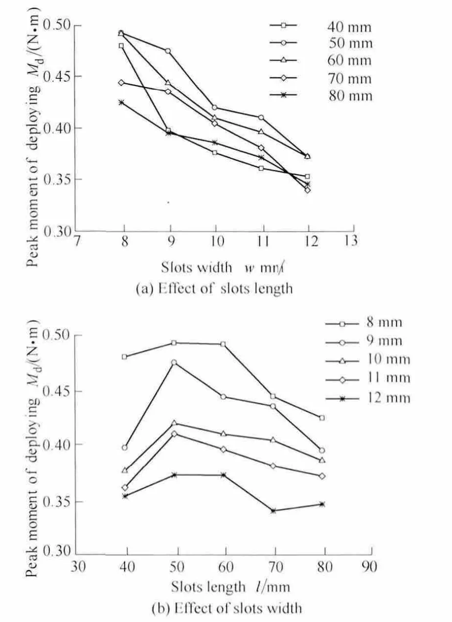
Fig.8.Variation of Mdwith slots length l and slots width w
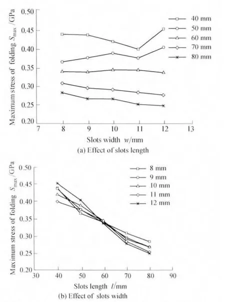
Fig.9.Variation of Smaxwith slots length l and slots width w
5.2 Effects of slots length and slots width on Md
Fig.8 shows the peak moment during TWTF hinges quasi-static deployment versus different slots length and slots width.It can be seen that the longer the slots length is,the lower the peak moment of deployment.But for l=40 mm the peak moment is lower than that for l=50 mm as shown in Fig.8(a).The reason is that the slots length is too small to fold the TWIF hinges.Moreover,it should be revealed that the narrower the slots width,the greater the peak moment of deployment as shown in Fig.8(b).When the slots length is changed from 40 mm to 80 mm,Mdis decreased from–23.8% to 17%.When the slots width is changed from 8 mm to 12 mm,Mdis decreased by 16.9%–26%.
5.3 Effects of slots length and slots width on Smax
Fig.9.shows the effects of the slots length and the slots width on Smaxin the complete folded configurations.It can be seen that the maximum stress is more sensitive to the slots length than the slots width.The Smaxcontinuously decrease as slots length increase with fixed slots width as seen from Fig.9(a).But when l=40 mm and l=50 mm the last value of Smaxfor each curve increase obviously,the reason is that when w≤11 mm and l≤50 mm the maximum stress locates in the middle of the dominates,and when w=12 mm or l≥60 mm the maximum stress locates on the transition from the slots length to the slots end circle.It is interesting to note that when l=60 mm all the Smaxapproximately equal with each other as shown in Fig.9(b),that’s because the special slots length l=60 mm of all the design points is most closed to the perimeter of the half circle described by the hinge in the folded position.If the slots length is closed to the perimeter,there would be a semicircle in the folding region,so the stress distribution is smoother.When the slots length is changed from 40 mm to 80mm,Smaxis decreased by 35%– 45%.When the slots width is changed from 8 mm to 12 mm,Smaxis decreased from–3% to 12%.
From the above results,it can be seen that both the slots length and the slots width have significant influences on Mfand Md,but Smaxis more sensitive to the slots length than the slots width.What’s more,an increase in Mdand Mfdue to a parameter change often leads to an increase in Smaxas well.But in some ways,Md,Mfand Smaxmay conflict with each other.
6 Conclusions
(1)The surrogate models of Mf,Mdand Smaxare obtained by RSM.These empirical equations is proven to be precise for this study.
(2)The optimal design is obtained by RSM polynomials for the TWTF hinge,this configuration has lower maximum stress,greater peak moment and smoother stress distribution.
(3)For the TWTF hinge,with greater slots length and slots width,Mfand Mdare generally lower.A greater slots length can lead to a much lower Smax,but the relationship is not observed between the slot width and the Smax.
[1]MARKS G W,REILLY M T,HUFF R L.The lightweight deployable antennas for the MARSIS experiment on the Mars express spacecraft[C]//Proceeding of the 36th Aerospace Mechanisms Symposium,Glenn Research Center,NASA CP-2002-211 506,April 2002:183–196.
[2]MANSFIELD E H.Large-deflexion torsion and flexure of initially curved strips[J].Proceedings of the Royal Society of London.Series A,Mathematical and Physical Sciences,1973,334(1598):279–298.
[3]SEFFEN K A,PELLEGRINO S.Deployment dynamics of tape springs[J].Proceedings of the Royal Society of London Series A,1999,455(1983):1003–1048.
[4]SEFFEN K A.On the behavior of folded tape-springs[J].Journal of Applied Mechanics-Transactions of the ASME,2001,68(3):369–375.
[5]SEFFEN K A,YOU ZHONG,PELLEGRINO S.Folding and deployment of curved tape springs[J].International Journal of Mechanical Sciences,2000,42:2055–2073.
[6]YEE J C H,PELLEGRINO S.Composite tube hinges[J].Journal of Aerospace Engineering,2005,18(4):224–231.
[7]SILVER M.Buckling of curved shells with free edges under multi-axis loading[D].Colorado:University of Colorado,2005.
[8]WARREN P A,SILVER M J,DOBSON B J,et al.Experimental characterization of deployable outer barrel assemblies for large space telescopes[C]//Proceedings of SPIE,UV/Optical/IR Space Telescopes and Instruments:Innovative Technologies and Concepts VI 886 008,October 29,2013.
[9]BOESCH C,PEREIRA C,JOHN R,et al.Ultra light self-motorized mechanism for deployment of light weight space craft appendages[C]//Proceedings of 39th Aerospace Mechanisms Symposium,Newport,NASA Marshall Space Flight Center,May,7–9,2008.
[10]LANE S A,MURPHEY T W,ZATMAN M.Overview of the innovative space-based radar antenna technology program[J].Journal of Spacecraft and Rockets,2011,48(1):135–145.
[11]WALKER S J I,AGLIETTI G.Study the dynamics of threedimensional tape spring folds[J].Journal of AIAA,2004,42(4):850–856.
[12]WALKER S J I,AGLIETTI G.Experimental Investigation of tape springs folded in three dimensions[J].Journal of AIAA,2006,44(1):151–159.
[13]KWOK K.Mechanics of visoelastic thin-walled structures[D].California:California Institute of Technology,2013.
[14]RIMROTT F P J,FRITSCHE G.Fundamentals of stem mechanics[C]//Pellegrino S and Guest S D,eds,IUTAM-IASS Symposium on Deployable Structures:Theory and Applications,Cambridge,UK,September,1998:321–333.
[15]BLOCK J,STRAUBEL M,WIEDEMANN M.Ultralight deployable booms for solar sails and other large gossamer structures in space[J].Acta Astronautica,2011,68(7–8):984–992.
[16]SOYKASAP O,PELLEGRINO S,HOWARD P,et al.Folding large antenna tape spring[J].Journal of Spacecraft and Rockets,2008,45(3):560–567.
[17]SOYKASAP O,KARAKAYA S,TURKMEN D.Curved large tape springs for an ultra-thin shell deployable reflector[J].Journal of Reinforced Plastics and Composites,2012,31(10):691–703.
[18]SOYKASAP O,WATT A,PELLEGRINO S.New deployable reflector concept[C]//Proceedings of 45th AIAA/ASME/ASCE/AHS/ASC Structures,Structural Dynamics and Materials Conference,Palm Springs,California,April,19–22,2004:1574.
[19]MARKS G.Flattenable foldable boom hinge:USA,6343442[P].2002-02-05.
[20]MOBREM M,ADAMS D S.Deployment analysis of lenticular jointed antennas onboard the mars express spacecraft[J].Journal of Spacecraft and Rockets,2009,46(2):394–402.
[21]SILVER M J,HINKLE J D,PETERSON L D.Modeling of snap-back bending response of doubly slit cylindrical shells[C]//Proceedings of 45th AIAA/ASME/ASCE/AHS/ASC Structures,Structural Dynamics,and Materials Conference,Palm Springs,California,April,19–22,2004:1820.
[22]YEE J C H.Thin CFRP composite deployable structures[D].Cambridge:University of Cambridge,2006.
[23]SOYKASAP O.Deployment analysis of a self-deployable composite boom[J].Composite Structures,2009,89(3):374–381.
[24]MALLIKARACHCHI H M Y C,PELLEGRINO S.Quasi-static folding and deployment of ultrathin composite tape-spring hinges[J].Journal of Spacecraft and Rockets,2011b,48(1):187–198.
[25]MALLIKARACHCHI H M Y C,PELLEGRINO S.Optimized designs of composite booms with integral tape-spring hinges[C]//Proceedings of 51st AIAA/ASME/ASCE/AHS/ASC Structures,Structural Dynamics,and Materials Conference,Orlando,Florida,April,12–15,2010:1–16.
[26]BOX G E P,WILSON K B.On the experimental attainment of optimum conditions[J].Journal of the Royal Statistical Society,1951,13:1–45.
[27]LIU Yucheng.Design optimization of taped thin-walled square tubes[J].International Journal of Crashworthiness,2008,13(5):543–550.
[28]LI Meng,DENG Zongquan,LIU Rongqiang,et al.Crashworthiness design optimization of metal honeycomb energy absorber used in lunar lander[J].International Journal of crashworthiness,2011,16(4):411–419.
[29]QI Chang,YANG Shu,DONG Fangliang.Crushing analysis and multiobjective crashworthiness optimization of tapered square tubes under oblique impact loading[J].Thin-walled Structures,2012,59,103–119.
[30]LI Meng,DENG Zongquan,GUO Hongwei,et al.Crashworthiness analysis on alternative square honeycomb structure under axial loading[J].Chinese Journal of Mechanical Engineering,2013,26(4):784–792.
[31]GUO Hongwei,ZHANG Jing,LIU Rongqiang,et al.Effects of joint on dynamics of space deployable structure[J].Chinese Journal of Mechanical Engineering,2013,26(5):861–872.
[32]LINDMAN H R.Analysis of variance in experimental design[M],Springer,New York,1992.
[33]MYERS R H,MONTGOMERY D C.Response surface methodology:process and product optimization using designed experiments[M].New York:Wiley,1995.
杂志排行

Chinese Journal of Mechanical Engineering的其它文章
- Mesoplasticity Approach to Studies of the Cutting Mechanism in Ultra-precision Machining
- Web Tension Regulation of Multispan Roll-to-Roll System using Integrated Active Dancer and Load Cells for Printed Electronics Applications
- Interactive Training Model of TRIZ for Mechanical Engineers in China
- Constant Speed Control for Complex Cross-section Welding Using Robot Based on Angle Self-Test
- Annoyance Rate Evaluation Method on Ride Comfort of Vehicle Suspension System
- Experimental Study on Occupant’s Thermal Responses under the Non-uniform Conditions in Vehicle Cabin during the Heating Period