Annoyance Rate Evaluation Method on Ride Comfort of Vehicle Suspension System
2014-02-07TANGChuanyinZHANGYiminZHAOGuangyaoandMAYan
TANG Chuanyin *,ZHANG YiminZHAO Guangyaoand MA Yan
1 School of Mechanical Engineering and Automation,Northeastern University,Shenyang 110004,China
2 Shenyang Academy of Instrumentation Science,Shenyang 110043,China
1 Introduction*
Recently,investigations into ride comfort and handling ability of vehicles have increased.The vehicle suspension system is not only responsible for guaranteeing its fundamental functions but also responsible for driving comfort and safety as the suspension carries the vehicle body and transmits all forces between body and road.Research on active suspensions for passenger vehicles have increased in recent years because ride comfort is much improved by the use of an active suspension system[1–5].
Generally speaking,the ride comfort includes the width of the vehicle,the field of vision,seat comfort,the degree of quiet and the magnitude of vibration of each part,while the commonly used ride comfort only refers to the adaptive degree of vibration of passengers.Ride comfort of vehicle indicates the effect of vibration and shock to the comfort of passengers during running.The weighted vertical acceleration mostly contributes to the uncomfortable feel of drives and passengers,the larger the acceleration is,the worse the ride comfort becomes.The research of ergonomics indicates that the vibration acceleration is one of the significant factors which affect ride comfort[6–11].
Vehicle suspension system performance is typically evaluated by its ability to provide road handling and passenger comfort.Current vehicles can only offer a compromise between these two conflicting criteria by providing spring and damping coefficients with fixed rates.Poor road handing capability and decreased passenger comfort are due to excess vehicle body vibrations,which resulting in biological effects on passengers,detrimental effect to cargo,etc.Active suspension control system aims to ameliorate these undesirable effects by isolating the vehicle body from wheel oscillations induced by uneven terrain.
The purpose of this paper is to propose a new evaluation method with respect to possible effects on health,the evaluation method based on annoyance rate.The proposed method can further estimate quantitatively the number of passengers who feel discomfort due to vibration.The paper is constructed as follows.First,the traditional evaluation methods of ride comfort during vehicle vibration are discussed;secondly,a fuzzily random evaluation model on the basis of annoyance rate for human body’s subjective response to vibration,with relevant fuzzy membership function and probability distribution given is presented.Then,a half-car four degrees of freedom suspension vibration model is described,subject to irregular excitations from the road surface,with the aid of software Matlab/Simulink.Furthermore,computer simulations demonstrate the effectiveness of the proposed schemes,based on ISO 2631/1(1982),ISO 2631–1(1997)and annoyance rate evaluation method,respectively.Finally,some concluding remarks are given.
2 Evaluation Method Ride Comfort
The evaluation method of ride comfort include Ride comfort coefficients;Average absorbed power;BS6841[12];VDI 2057[13];NASA single uncomfortable index method and ISO method[14].
(1)Ride comfort coefficients.The ride comfort coefficients method based upon basic allowed critical curve advised by Janeway[15],it is mainly applied on the evaluation of vehicle and other transportation instrument.The multiple of comparison of vibration signal and the basic curve is the RCL coefficients.
(2)Average absorbed power.Average absorbed power was developed by the US Army Tank-Automotive Command in 1966[16].Frequency weighting ranges between 1 Hz and 80 Hz.Below 1 Hz the method is not successful.The AP weighting curve strongly emphasizes the visceral resonance around 4–5 Hz because most energy is absorbed in these softer tissues.
(3)BS6841.The BS6841 standard considers a frequency range of 0.5–80 Hz.For each axis a component ride value can be determined as well as an overall ride value.The frequency range is extended to 0.5 Hz to compensate for measurements of motion sickness.
(4)VDI 2057.In 1963 the Society of German Engineers published the first VDI 2057 standard making them the first to produce a standard to quantify ride comfort.In principle the VDI standard defines a calculated ride comfort index(K-factors)that is compared with a subjective table to determine the ride as subjectively experienced by humans.
(5)NASA single uncomfortable index method.The method transform the acceleration from five directions and physical measurement value of noise to subjective uncomfortable index according to statistical experience formula,then the single uncomfortable index is obtained by certain expression of every uncomfortable index,and the single uncomfortable index is used to evaluate comfort.
(6)ISO.National and international standards have provided procedures for evaluating human exposure to whole-body vibration and repeated shock.International Organization for Standardization,ISO 2631 is the most popular evaluation method in the world currently.The measurements were analyzed according to the recommendations in International Standard 2631.This involved the application of frequency weightings,the use of multiplying factors to allow for differing sensitivity of the body in different axes,the calculation of root mean square values and the summation of values over the different axes.
(a)ISO2631–1982.ISO2631–1982 Evaluation Manual of Human Exposure to Whole Body Vibration proposed that vibration acceleration,effective value,vibration direction,vibration frequency and vibration duration time are the four fundamental coefficients to evaluate the effect of human exposure to whole body vibration.GB/T 13442–1992 Evaluation Index to Human Exposure to Whole Body Vibration Ride Comfort Reduction and GB/T 1344l–1992Measurement Criterion to Vibration Environment to Whole Body Vibration refer to ISO 2631/1–l985 Evaluation of Human Exposure to Whole Body Vibration–Part 1:General Requirements.
(b)Improved evaluation method ISO 2631–1–1997.International Organization for Standardization,ISO 2631–1 Mechanical Vibration and Shock-evaluation of Human Exposure to Whole Body Vibration–Part 1:General Requirements,1997 proposed the improved evaluation method.
The basic evaluation method for vibration is calculated using weighted root mean square acceleration.If the basic evaluation method underestimates the vibration,the additional methods are vibration dose value(VDC)and maximum transient vibration value(MTVV).Table 1 shows the comfort reaction to vibration environments.
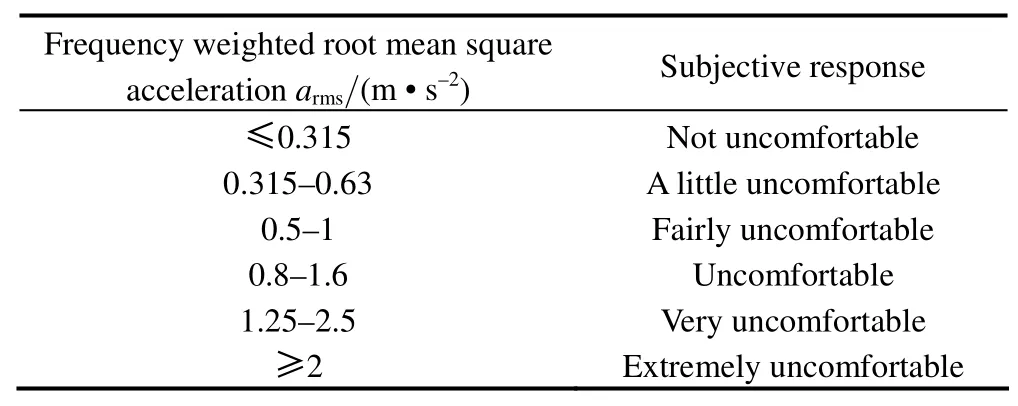
Table 1.Comfort reaction to vibration environments
3 Evaluation Method Based on Annoyance Rate
IS02631-1982 Mechanical Vibration and Shock Evaluation of Human Exposure to Whole Body Vibration establishes different allowed vibration intensity[aw]according to different conditions,and divide the subjective response of human being into two parts:comfort and discomfort,but the limit must ignore many factors,such as the activities that people engage and tolerance level for risk of external environment.A lot of research work has been done by investigators around the world.MAEDAA,et al[17],proposed the effect of frequency content to the evaluation of subjective responses to whole-body vibration exposure.GRIFFIN,et al[18],studied the effects of frequency,magnitude,damping,and direction on the discomfort of vertical whole-body mechanical shocks.PADDAN,et al[19],studied the evaluation of whole-body vibration in vehicles and provoke that ISO 2631 allows”appreciably”longer daily exposures to whole-body vibration than BS 6841.Many different psychological,psychophysical and physical factors,such as individual susceptibility,body characteristics and posture together with the frequency,direction,magnitude and duration of vibration are relevant in development of unwanted effects.The annoyance threshold acceleration determined by the two valued logic method can not describe the ambiguity and randomness existing in human response to vibration environments,which results in many uncertainties in the vibration comfort based reliability analysis.All these uncertainties were analyzed from a view point of psychophysics.The membership function and corresponding conditional probability distribution were determined based on the format of field survey table and laboratory findings.A fuzzy stochastic model for human response to vibrations was presented.SONG,et al[20–21],combined the fuzzy logic method,the probability theory and the experimental statistics,to advance a new evaluation index,i.e.,annoyance rate method.
The annoyance rate method is not only founded upon the fuzzy logic method and the probability theory,but also is constituted by signal detecting theory of psychophysics.The annoyance rate adopts the membership function,which was concluded through a series of internationally famous vibration comfort trial from 1931 to 1990,and the random distributing format[22–24]was directly established on test and experiment.
Annoyance rate is the rate of unacceptable response under certain vibration intensity.The vibration sensitivity is different according to different range of frequency.The root mean square(vibration intensity)of weighted frequency is adopted internationally as the foundation for evaluating the vibration comfort.The vertical general frequency weighted function can be expressed as follows[25]:

For vibration signal of frequency f,if its maximum acceleration is amax,then the vibration intensity is aw=Wfjμ-1amax,where μ is the maximum value factor.According to the statistics of structural vertical vibration acceleration response,μis 2.5[26].
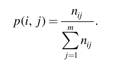
Annoyance rate indicates the ratio of people who cannot accept the external stimulus to the total statistical people.It can be used to determine the annoyance threshold for vibration comfort.Annoyance threshold means the limit of acceleration on the premise of ensuring acceptable comfort.Under discrete distribution,the annoyance rate can be expressed as

where A(awi)is the annoyance rate of the ith vibration intensityawi;nijis the number of subjective response of the jth type of the ith vibration intensity;vjis the membership value of the jth type of the unacceptable range,and vj=(j-1)/(m-1);m is the class number of the subjective response,if the class of“no vibration feeling”,“a little vibration feeling”,“medium vibration feeling”,“strong vibration feeling”,“Extremely uncomfortable”are adopted to describe the subjective response of occupant,then m=5;p(i,j)represents the difference of the subjective feeling degree of the occupant,and
Considering the continuous distribution,calculation formula of annoyance rate is represented as

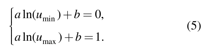
where awis the frequency weighted vibration intensity;δis the vibration coefficients,and change from 0.1 to 0.5,based on trial research;v(u)is the fuzzy membership function of vibration intensity,is shown as follows:

where uminis the top limit of“no feeling”to vibration of the occupant;umaxis the bottom limit of“Extremely uncomfortable”to vibration of human being.
The coefficients of a,b can be obtained from the following equation:
4 System Models and Control Algorithm
4.1 System model
A schematic diagram of active suspension control system is shown in Fig.1,the half-body suspension system is represented as a four degrees of freedom system.The assumptions during the process of modeling are considered as following:(1)The irregular road excitation of the left tire and right tire is same,the vehicle is symmetrical to the longitudinal line,thus the roll and yaw movement is omitted;(2)The vehicle body,including the engine part is considered as a rigid body,which means the effect of the engine is neglected.The vehicle consists of a single sprung mass connected to two unsprung masses;(3)The axle and the tires connected are regarded as the unsprung mass,the contact manner of the center tire line and the road is point to point method;(4)The tires are modeled as simple linear springs without damping.For simplicity,all pitch angles are assumed to be small[27–29].
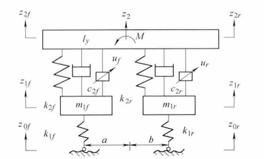
Fig.1.Half body four degrees of freedom model
After applying a force-balance analysis to the model in Fig.1 the dynamics equation is governed by

This results in the system state variables below:

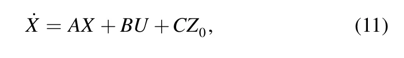
The state space equations in matrix are given by
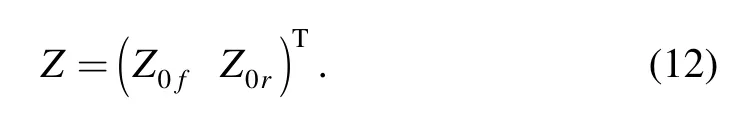
with the disturbance input defined as
Denoting the irregular road excitation as band limited white noise,which is determined by different road surface condition and velocity,the equations of font and rear road,are expressed as follows:

where f0is the lowest frequency,irregular road coefficients Gq(n0)=64×10-6m2/m-1and velocity is 30 m/s.
4.2 Control algorithm
Genetic algorithm is a stochastic global search method which is based on the metaphors of natural biological evolution,according to Darwin(1809–1882)evolution theory[30].Neural network provides a fast method for autonomously learning to produce a set of output states,given a set of input states[31].
The combination of neural network and genetic algorithm is one methods of the scientific optimization arithmetic.The proportion of the index,the spring mass and the suspension stiffness have important influence on the stability of the system.Based on genetic algorithm and neural network control theory,the control systems of the active suspension are obtained.In particular,emphasis is placed on the minimization of the vertical acceleration of the vehicle body from the view-point of passenger ride comfort.The block diagram of system is shown as Fig.2.

Fig.2.Block diagram of system
To consider the ride comfort and drive stability synthetically,the spring mass acceleration,tire dynamic load and suspension deflection are selected as the significant indexes for the evaluation of active suspension control effect,and the weighted objective function is generally defined by the following equation:

And yf=z3-aθ-z4;yr=z2+bq-z6;z1is the passenger displacement;z2is the vehicle body vertically displacement;θis the pitching angle.
The fitness function f is given byf=1/J.The objective function includes not only the sprung mass acceleration,the sprung pitching acceleration,but also the suspension deflection and the dynamic tire load.And ρ1,ρ2,ρ3,ρ4,ρ5are the weighted coefficients of the sprung mass acceleration,the sprung pitching acceleration,the passenger acceleration,the suspension deflection and the dynamic tire load,respectively.
To take advantage of genetic algorithms as well as neural network,we implement the combination of genetic algorithm and neural network in this paper to solve the vehicle suspension problem.In the present work,0.8 is the considered probability rate of the crossover,a value of 0.02 is the considered probability for mutation.The NN of this active control system has two hidden layers,the input neuron is 1,the hidden neurons are 100 and 3,respectively,and the output neuron is 1.The advanced back propagation is adopted and we added momentum in the back propagation to prevent the network from getting stuck in a shallow local minimum point.An adaptive learning rate was applied to decrease the training by keeping the learning reasonably high while insuring stable learning.We pick random values as initial weights and biases.
The mathematical expression of back propagation with momentum can be written as
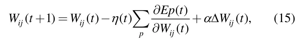
where η is the learning coefficients and α is the coefficient of momentum.
5 Evaluation of Ride Comfort
The experiments are done on the some test road,sensors are placed on the vehicle body.Fig.3 indicates the piratical experimental data of body acceleration,and Fig.4 indicates the simulation result of body acceleration.The root mean square value of weighted acceleration is 3.497 8 m/s2and 3.567 7 m/s2,which indicates the simulation results are credible.
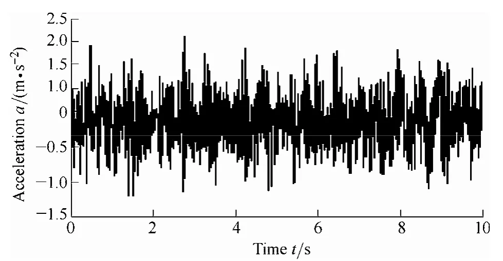
Fig.3.Experimental data of body acceleration
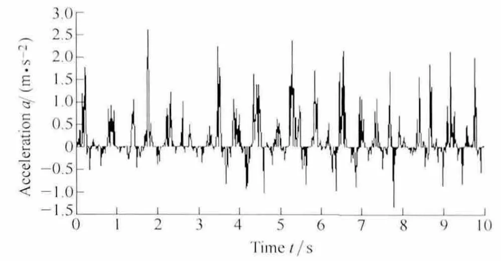
Fig.4.Simulation result of body acceleration
5.1 Standard of ISO 2631/1–1982 evaluation method
According to the research of ride comfort,the main reason for the discomfort of passengers and drivers is the vertical acceleration within certain frequency.The larger the acceleration value is the more discomfort the occupant feels.The vibration accelerations are the main factor which causes the discomfort of passengers and drivers based on the study of ergonomics.The four degrees of freedom vibration model of suspension is shown in Fig.1,then the dynamic equation is obtained.Fig.5 represents the frequency weighted root mean square acceleration before control.

Fig.5.Weighted root mean square acceleration before control
The root mean square value of weighted acceleration before control is 2.537 7 m/s2,consulted to Table 1,the table of comfort reaction to vibration environments,the subjective response of the occupant before control is very uncomfortable.The control algorithm of genetic algorithm and neural network control is proposed to control the four degrees of freedom vibration system of Fig.5.Fig.6 indicates the weighted root mean square acceleration after control.

Fig.6.Weighted root mean square acceleration after control
The root mean square value of weighted acceleration after control is 1.078 0 m/s2,consulted to Table 1,the table of comfort reaction to vibration environments,the subjective response of human body after control is uncomfortable.
5.2 Standard of ISO 2631/1–1997 evaluation method
Fig.7 indicates the weighted root mean square acceleration before control according to standard of ISO 2631/1–1997 method.
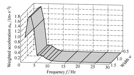
Fig.7.Weighted root mean square acceleration before control
The root mean square value of weighted acceleration before control is 1.673 9 m/s2,consulted to Table 1,the table of comfort reaction to vibration environments,the subjective response of human body before control is very uncomfortable.
The control algorithm of genetic algorithm and neural network control is proposed to control the four freedom vibration system of Fig.1.Fig.8 indicates the weighted root mean square acceleration after control.The root mean square value of weighted acceleration after control is 0.398 4 m/s2,consulted to Table 1,the table of comfort reaction to vibration environments,the subjective response of human body before control is a little uncomfortable according to the standard of ISO 2631/1–1997 evaluation method.
Fig.9 indicates the comparison of weighted root mean square acceleration before control between the standard of ISO 2631/1–1997 evaluation method and standard of ISO 2631/1–1982 evaluation method.And Fig.10 represents the comparison of weighted root mean square acceleration after control between the standard of ISO 2631/1–1997 evaluation method and standard of ISO 2631/1–1982 evaluation method.From the simulation results,we can see that the weighted root mean square accelerations of two standards are similar beyond frequency of 5 Hz.

Fig.8.Weighted root mean square acceleration after control

Fig.9.Comparison of weighted root mean square acceleration before control
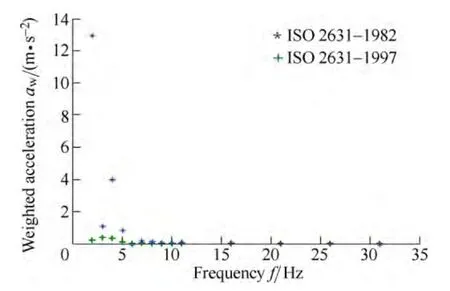
Fig.10.Comparison of weighted root mean square acceleration after control
Table 2 shows the amelioration of comfort reaction to vibration environments and the change of body acceleration after control of genetic and neural network algorithm.From the simulation results,we can see that the reduction of weighted root mean square acceleration is 57.5%,according to standard of ISO 2631/1–1982 evaluation method,and the amelioration of ride comfort change from extremely uncomfortable to uncomfortable.The reduction of weighted root mean square acceleration is 57.5%.According to standard of ISO 2631/1–1997 evaluation method,the reduction of weighted root mean square acceleration is 76.2%.And the amelioration of ride comfort change from very uncomfortable to a little uncomfortable,the ride comfort is greatly advanced.

Table 2.Comparison of comfort reaction to vibration environments between before and after control
5.3 Ride comfort based on annoyance rate evaluation method
The programs of annoyance rate are programmed through M-file of software Matlab[32–33].Fig.11 indicates the corresponding curve of annoyance rate,and Fig.12 presents the relationship of annoyance rate to vibration frequency and weighted acceleration.

Fig.11.Corresponding curve of annoyance rate

Fig.12.Relationship of annoyance rate to vibration frequency and weighted acceleration
The control algorithm of genetic algorithm and neural network control is programmed by M-file of software Matlab.Fig.13 indicates the corresponding curve of annoyance rate after control,and Fig.14 presents the relationship of annoyance rate to vibration frequency and weighted acceleration after control.

Fig.13.Corresponding curve of annoyance rate after control
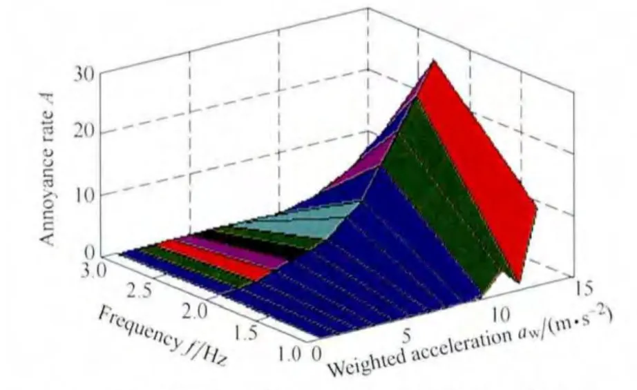
Fig.14.Relationship of annoyance rate to vibration frequency and weighted acceleration
In this work,Approaches are presented for suspension design which uses neural network control algorithm.It is obvious from the response plots that vehicle acceleration response decreased compared with the passive suspension system.The simulation results indicate that the neural network algorithm is effective in ameliorating the ride comfort.
6 Conclusions
(1)Based on ISO 2631/1–1982,ISO 2631/1–1997 and annoyance rate respectively,simulated assessment results indicate that the amelioration of ride comfort change from very uncomfortable to a little uncomfortable,thus the proposed active suspension systems prove to be effective in the vibration isolation of the suspension system.
(2)With the improvement of frequency from 0.5 Hz to 4 Hz,the annoyance rate increases accordingly,and the annoyance rate reaches the extreme value to 49% and 37%for the condition before and after control respectively,and the annoyance rate decreases rapidly between the frequency of 8 Hz to 15 Hz,and decreases more slowly above the 25 Hz.The annoyance rate evaluation method includes the fuzzily random evaluation model with the combination of signal inspection theory analysis and human body’s uncertain response to vibration,comprises the relevant fuzzy membership function and probability distribution.The method is the supplement of the traditional evaluation method,which can further quantitatively estimate the number of passengers who feel discomfort due to vibration.
[1]SANKARANARAYANAN V,EMEKLI M E,GUVENC B A,et al.Semi-active suspension control of a light commercial vehicle[J].IEEE/ASME Transactions on Mechatronics,2008,13(5):598–604.
[2]SHAN X M,KUO S K,ZHANG J,et al.Ultra precision motion control of a multiple degrees of freedom magnetic suspension stage[J].IEEE/ASME Transactions on Mechatronics,2002,7(1):67–78.
[3]CROLLA D,YU Fan.Vehicle dynamics and control[M].Beijing:Press of People Communication,2004.(in Chinese)
[4]WILLIAMS D E,HADDAD W M.Active suspension control to improve vehicle ride and handling[J].Vehicle System Dynamics,1997(28):l–24.
[5]BOUAZARA M,RICHARD M J,RAKHEJA S.Safety and comfort analysis of a 3-D vehicle model with optimal non-linear active seat suspension[J].Journal of Terra-mechanics,2006,43:97–118.
[6]ZHOU Yiming,MAO Enrong.Vehicle ergonomics[M].Beijing Technology University,1999.
[7]JONSSON P,JOHANSSON O.Prediction of vehicle discomfort from transient vibrations[J].Journal of Sound and Vibration,2005,282(3):1043–1064.
[8]FALOU W E,DUCHENE J,GRABISCH M,et al.Evaluation of driver discomfort during long-duration car driving[J].Applied Ergonomics,2003,34:249–255.
[9]LEWIS C H,GRIFFIN M J.A comparison of evaluations and assessments obtained using alternative standards for predicting the Hazards of whole-body vibration and repeated shocks[J].Journal of Sound and Vibration,1998,215(4):915–926.
[10]RIHER H,MEISTER F J.The sensitiveness of the human body to vibration[J].Forschung(VDI-Berlin),1931,2:381–386.
[11]DAHLBERG T.Ride comfort and road holding of A 2-DOF vehicle travelling on a randomly profiled road[J].Journal of Sound and Vibration,1978,58(2):179–187.
[12]BS 6841 Measurement and evaluation of human exposure to whole-body mechanical vibration and repeated shock[S].British Standards Institution,1987.
[13]VDI 2057 Human exposure to mechanical vibration whole-body vibration[S].Verein Deutcher Ingenieure,2002.
[14]ISO 2631–1 Mechanical vibration and shock-evaluation of human exposure to whole-body vibration–part 1:general requirements[S].International Organization for Standardization,1997.
[15]Janeway.Human Vibration Tolerance Criteria and Applications to Ride Evolution[R].SAE:750075
[16]IYAMA T,ONISHI T.Absorbed power measurement method.United States Patent Application,20110301886[P].2010-01-29.http://patent.ipexl.com/U2S/20110301886.html.
[17]MAEDAA S,MANSFIELDB N J,SHIBATAA N.Evaluation of subjective responses to whole-body vibration exposure:Effect of frequency content[J].International Journal of Industrial Ergonomics,2008,38:509–515.
[18]AHN S J,GRIFFIN M J.Effects of frequency,magnitude,damping,and direction on the discomfort of vertical whole-body mechanical shocks[J].Journal of Sound and Vibration,2008,311(1–2):485–497.
[19]PADDAN G S,GRIFFIN M J.Evaluation of whole-body vibration in vehicles[J].Journal of Sound and Vibration,2002,251(1):195–213.
[20]SONG Zhigang,JIN Weiliang.A fuzzy-stochastic model for human response to vibrations[J].Journal of Basic Science and Engineering,2002,10(3):287–294.
[21]SONG Zhigang,JIN Weiliang.Serviceability design of ice induced platform vibration based on ice zoning map of Bohai Sea-Acceptable acceleration levels[J].The Ocean Engineering,2005,123(12):61–65.
[22]OBOME D J,CLARKE M J.The determination of equal comfort zones for whole-body vibration[J].Ergonomics,1974,17(6):769–782.
[23]TU Ruihe,ZHAN Jiakai,SUN Jiaqi,et al.An investigation on community response to environmental vibration[J].Environment Science,1990,32(3):70–73.
[24]YAMAGUCHI H,DOI S I,IWAMA N,et al.Experimental study of system optimization for suppression of vehicle vibration[J].Vehicle System Dynamics,1993,22:299–308.
[25]GRIFFIN M J.Handbook of human vibration[M].London:Academic Press,1994.
[26]SONG Zhigang,JIN Weiliang.Vibration serviceability analysis of floor structures under pedestrian loads[J].Journal of Vibration Engineering,2005,18(3):288–292.
[27]YU Zhisheng.Automobile theory[M].Beijing:China Machine Press,2002.(in Chinese)
[28]ZHANG Tiezhu.Principle of automobiles[M].National Safeguard Industrial Press,2003.(in Chinese)
[29]GILLESPIE T D.Basic principle of vehicle dynamics[M].Beijing:Tsinghua University Press,2006.(in Chinese)
[30]ZHANG Wenxiu,LIANG Yi.Mathematical base for genetic algorithm[M].Xi’an:Press of Xi’an Jiaotong University,2001.(in Chinese)
[31]ZHANG Lirao,YAN Pingfan.Neural network and fuzzy logic control[M].Beijing:Press of Tsinghua University,1998.(in Chinese)
[32]XUE Dingyu,CHEN Yangquan.System Simulation technology and appliance Based on MATLAB/Simulink[M].Beijing:Tsinghua University Press,2002.
[33]LIU Jinkun.Simulation based on MATLAB of advanced PID control[M].Beijing:Electronic Industry Press,2004.(in Chinese)
杂志排行

Chinese Journal of Mechanical Engineering的其它文章
- Intelligent Identification of Wear Mechanism via On-line Ferrograph Images
- Investigation of CFD Calculation Method of a Centrifugal Pump with Unshrouded Impeller
- Experimental Model and Analytic Solution for Real-time Observation of Vehicle’s Additional Steer Angle
- Experimental Study on Occupant’s Thermal Responses under the Non-uniform Conditions in Vehicle Cabin during the Heating Period
- Optimizing the Qusai-static Folding and Deploying of Thin-Walled Tube Flexure Hinges with Double Slots
- Constant Speed Control for Complex Cross-section Welding Using Robot Based on Angle Self-Test