Analysis of condition monitoring methods for electromotor on oil platform
2013-12-20LIJinDONGXinhong董欣红LIShaohua李少华HEShanTAOJianYANGZaijiang杨在江
LI Jin (李 进), DONG Xin-hong (董欣红), LI Shao-hua (李少华), HE Shan (何 杉), TAO Jian (陶 建), YANG Zai-jiang (杨在江)
(Oilfield Construction Engineering Company, Energy Technology and Services Company, China National Offshore Oil Corporation, Tianjin 300452, China)
Analysis of condition monitoring methods for electromotor on oil platform
LI Jin (李 进), DONG Xin-hong (董欣红), LI Shao-hua (李少华), HE Shan (何 杉), TAO Jian (陶 建), YANG Zai-jiang (杨在江)
(Oilfield Construction Engineering Company, Energy Technology and Services Company, China National Offshore Oil Corporation, Tianjin 300452, China)
Electromotor on oil platform often has mechanical failures. In order to achieve monitoring and diagnosis of the electromotor, common diagnostic methods of electromotor are summarized first, and then vibration monitoring is regarded as a suitable method for monitoring and diagnosing of mechanical failures by comparing the advantages and disadvantages of each method and characteristics of mechanical faults. At last, the fault frequencies and arrangements of vibration measuring points are analyzed. By using vibration monitoring method, the diagnosis of bearing faults of electromotor is carried out. The results show that the analysis of condition monitoring methods for electromotor is meanning for machine maintenance and repair, and it lays foundation for computerized repair system and resource management system.
oil platform; electromotor; condition monitoring; vibration; offline
CLD number: TP277 Document code: A
0 Introduction
Electromotor is widely used as a driving device for moving equipment on oil platform, and the status of electromotor is related to the safety in production and economic benefit for oil platform. At present, the oil platform mainly adopts manual inspection to maintain equipments, but regular maintenance mode often has the following defects[1]: (1) The fact that electromotor breaks down before ragular mainenance cycle causes lack of maintenance; (2) It is easy to cause unnecessary power loss, human loss, property loss and so on; (3) People usually have uneven abilities for maintenance, so it is easy to reduce the operational reliability of the equipment.
In order to realize computerized maintenance system or enterprise resource management system, it is inevitable to carry out condition monitoring for oil platform, including offline monitoring and online monitoring. No matter which kind of technologies is used, there exist the following advantages: (1) The unnecessary shutdown overhaul will be avoided, and the larger amount of damage for maintenance can be reduced at the same time; (2) The required manpower, material resources and properties can be reduced, and the economic benefit will increase; (3) The improper maintenance caused by accident also can be reduced. Now, there are many areas where research on electromotor detection has been done, but there is little research on electromotor detection in oil platform environment at present. Because oil platform is very special environment and many methods are not feasible, we plan to get a method that is suitable for electromotor to monitor and diagnose mechanical faults on oil platform by analyzing the used diagnostic methods.
1 Analysis of common diagnostic methods
1.1 Electrical monitoring
We can get and analyze the input current signal of stator winding by setting up the current sensor on the main return circuit of electromotor. Then we estimate the working condition by analyzing current characteristics or comparing the normal response with the response from external forced pulse. This mothod can diagnose many faults such as casting interspace, mechanical unbalance, spindle bending and so on[2]. It is not the same as regular load of pumping unit because the rotating mechanical equipment has tiny changing load on oil platform and can reach stable running state.
1.2 Temperature monitoring
Electromotor can enforce transformation from electric energy to mechanical energy, however it may bring out heat at the same time. The process of producing heat is very stable, but the quantity of heat and temperature should increase as the mechanical equipment breaks down. We can use infrared thermometer, infrared thermal imaging technology, etc. on iron core, slip ring, carbon brush and distribution box of electromotor to monitor pumping unit, thus we can diagnose potential electric faults[3]. However, the failure mode that causes the temperature changing is more complicated, and the reliability of temperature monitoring is poor.
1.3 Chemical monitoring
We can take some ways to get a judgement on damage severity of the related parts. Firstly, we test the resolvent of degraded insulation materials and lubricating oil, some of which wear debris of bearing and seal, and then they are compared with some chemical composition contents[4]. Unfortunately, this method can not carry out the corresponding chemical analysis on oil platform, so it has certain limitations to diagnosis of common mechanical faults.
The oil platform often suffers from stress deformation, which results in misalignment faults of electromotor, therefore the electromotor easily has a mechanical problem. According to the statistics, the mechanical faults of electromotor accounts for 90% of all faults. The paper published by British in 1984 shows that profitability and investment ratio of vibration monitoring for electromotor is 17∶1[4]. We also analyze and get one more suitable vibration monitoring methods to monitor mechanical fault of electromotor, but sometimes large electromotor control cabinet has realized monitoring of electrical parameters and temperature parameters. Therefore we can take vibration monitoring as the main way and electrical monitoring and temperature monitoring as the auxiliary ways to monitor electromotor. Now rotating equipment has adopted offline vibration monitoring on the oil platform, and online vibration monitoring will be used in the future.
1.4 Vibration monitoring
Machine body, its frame and load constitute a complex mechanical system that can vibrate freely with its inherent frequency or vibrate compulsively with more different frequencies, and electromotor will gradually break down because of mechanical damage or high noise produced by vibration[5]. With vibration monitoring, we can not only find the causes and location of the existing faults, especially being effective for mechanical damage diagnosis, but also analyze the damage force on the electromotor as well as predict the potential fault mode of electromotor at the same time[4,6].
Generally, we select machine case of electromotor shell as vibration monitoring points. The vibration information includes not only the motor own vibration signal, but also coupling signal of machine such as bearing equipment, etc. So it is important to process and identify signal of vibration monitoring. The diagnosis objects of vibration monitoring mainly include bearing damage, shaft bending, balance problem, bolt looseness, core resonance, large clearance of rotor, etc.
2 Measuring point arrangement and analysis methods
2.1 Measuring point arrangement of electromotor
Fig.1 shows the structure model of electromotor driving mechanical equipment. Taking the electromotor driving circulating water pump for production as an example, the measuring points of electromotor are mainly arranged in level driving point 2H, vertical driving point 2V, surface driving point 2A, level not-driving point 1H and vertical not driving point 1V. Thus coupling of rotor vibration signal and load vibration signal can be delivered to the bearing end to get more fault information and accurate diagnosis of electromotor running state.

Fig.1 Structure diagram of electromotor driving circulating water pump for production
2.2 Analysis methods of vibration signal
At present, the analysis methods of vibration signal include time domain analysis, frequency domain analysis and envelope analysis[7]. Each method has its own characteristics. The time domain analysis mainly analyzes the system stability, transient state performance and steady state performance, and it is very intuitive and accurate; The frequency domain analysis can reflect the seriousness of the vibration by amplifying and identifying vibration source by frequency at the same time, and spectrum signals include original frequency domain signal and converted frequency domain signal with fast fourier transform (FFT); Envelope analysis mainly focuses on the impact of the vibration signal, and it can analyze the early faults of bearing and gear mesh, but the envelope signal is decided by the wave failure that producs original signal, not by the severity of failure.
2.3 Analysis of common characteristic frequencies
The common characteristic frequencies are presented in the following[8].
Working frequency of rotor is
f=n/60,
where n is rotating speed of rotor.
Failure frequenies of bearing include
1) Rotating frequency of inner ring
fr=n/60;
2) Failure frequency of cage
fc=0.5fr(1-cosα·d/D);
3) Failure frequency of outer ring
Zfc=0.5Zfr(1-cosα·d/D);
4) Failure frequency of inner ring
Zfi=0.5Zfr(1+cosα·d/D);
where Z is the number of rolling element, a is contact angle, D is pitch diameter of bearing and d is diameter of bearing.
Meshing frequency of gear is
ft=c·f.
where c is the number of teeth.
The characteristics of other failure frequencies are as follows.
1) The eccentricity of rotor will produce two times higher line frequency vibration and frequency band, and its width is equal to passing frequency of electrode that can be generated at the same time.
2) The fractured rotor bar and short circuit ring, bad connecting rotor bar with short circuit ring and cutting-out rotor can produce one time high frequency vibration and frequency band, and its width is equal to passing frequency of electrode that can be generated at the same time. In addition, there is the same side frequency band in all times frequency of electromotor speed.
3 Experimental analysis
Taking the electromotor driving crude oil pump as an example, the parameters are as follows: electromotor manufacturer is Asea Brown Boveri Ltd. and parameters are 915 kW, 6 000 V/50 Hz/95 A, 2 988 rpm; bearing is 6319M/C3. Table 1 shows vibration velocities of measuring points, which are not big.
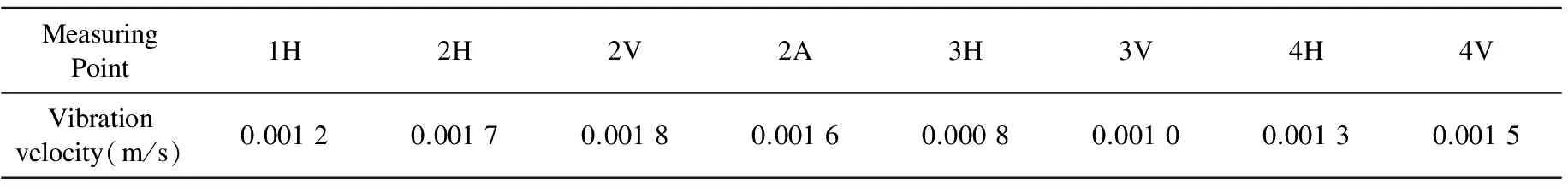
Table 1 Vibration velocities of measuring points
It can be concluded from Figs.2-6 that acceleration spectrum of driving ends illustrates bearing failure frequency and its harmonics, and the driving end bearing of motor shows early failure. According to the analysis, it also can be concluded that the system can continue to run and have good lubrication for bearing. We need to pay attention to the changes of vibration, noise and temperature.
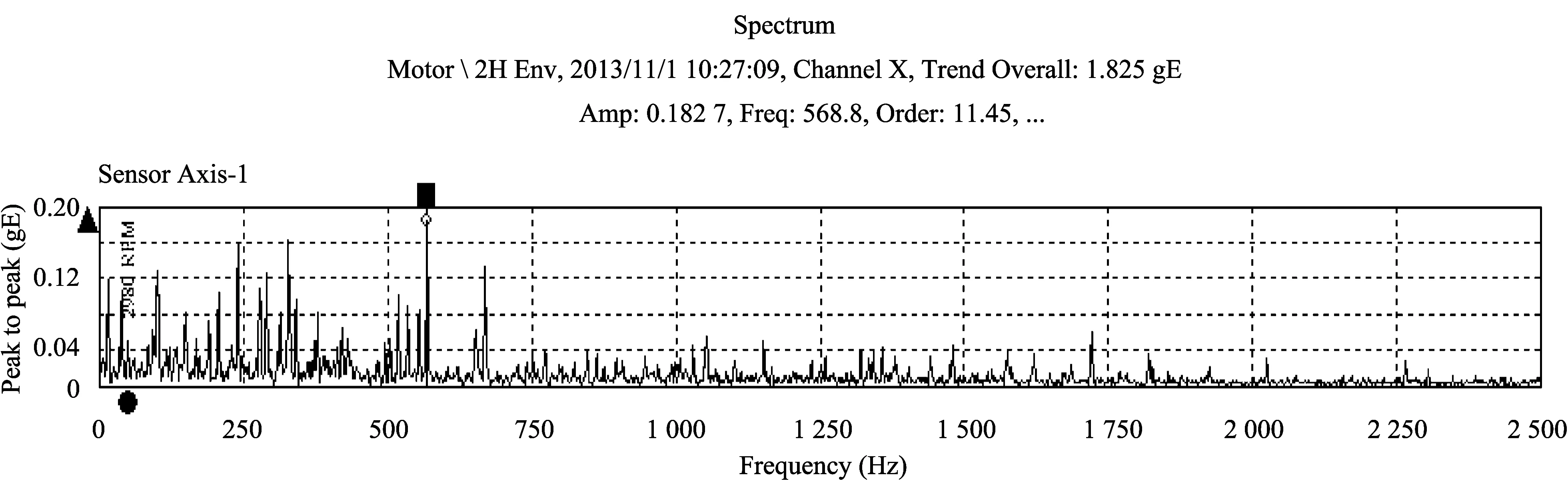
Fig.2 Envelope value of 2H in frequency

Fig.3 Envelope value of 2V in frequency
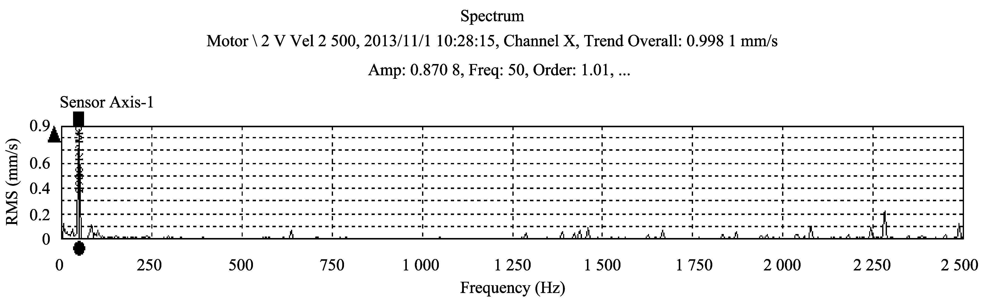
Fig.4 Velocity value of 2V in frequency
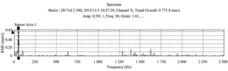
Fig.5 Velocity value of 2H in frequency

Fig.6 Velocity value of 2A in frequency
4 Conclusion
According to the above analysis, we can predict and diagnose the state and mechanical faults of electromotor. It is meaningful to realize machine maintenance and repair, enhance oil platform economic benefit and carry out computerized repair system and resource management system.
[1] RONG Ming-zhe, JIA Shen-li, WANG Xiao-hua. State detection of electrical equipment. Beijing: China Machine Press, 2010.
[2] LIU Mu-shuang, CAI Guang-xin, XIE Ying. Remote intelligent fault diagnosis of beam pumping unit. Oil Field Equipment, 2006, 35(5): 15-18.
[3] CHEN Yi-guo,YANG Hong-mao. Condition monitoring and fault diagnosis of beam pumping unit. China Plant Engineering, 2009,1: 37-39.
[4] MA Hong-zhong. Condition monitoring and fault diagnosis of machine. Beijing: China Machine Press, 2007.
[5] HAN Dong-wu. The analysis and monitoring of causes of electric machine. Journal of Electric Power, 2009, 18(4): 281-282.
[6] LIANG Xin-xin. State and prospect of the induction motor online fault detection. Micro Motors, 2011, 44(9): 75-78.
[7] CHANG Xi-chang. Processing methods of vibration signal and vibration monitoring and fault diagnosis of enterprise equipment. Signal Processing, 2009, 12(14): 84-88.
[8] WU Xin,Pong M H,Lee C M, et al. Reduction of EMI by electric field method. In: Proceedings of the 4th Annual Applied Power Electronics Conference and Exposition(APEC'99), Dallas, Texas, USA, 1999, 1: 135-138.
date: 2013-07-12
LI Jin (lj1912@163.com)
1674-8042(2013)04-0325-05
10.3969/j.issn.1674-8042.2013.04.005
杂志排行
Journal of Measurement Science and Instrumentation的其它文章
- A 4-layer method of developing integrated sensor systems with LabVIEW
- Calibration and compensation methods of installation error of electronic compass
- Design of shared bus DSP board in vector network analyzer
- Error modeling and analysis of inclinometer based on digital accelerometer
- U disk recorder based on CH376 and ATmega 128
- A measurement system for YTO