Calibration and compensation methods of installation error of electronic compass
2013-12-20FANChengye范成叶LIJieJINGZengzeng景增增ZHANGXiaoming张晓明
FAN Cheng-ye (范成叶), LI Jie (李 杰),2, JING Zeng-zeng (景增增), ZHANG Xiao-ming (张晓明),2
(1. Science and Technology on Electronic Test & Measurement Laboratory,North University of China,Taiyuan 030051, China;2. Key Laboratory of Instrumentation Science & Dynamic Measurement (North University of China), Ministry of Education, Taiyuan 030051, China)
Calibration and compensation methods of installation error of electronic compass
FAN Cheng-ye (范成叶)1, LI Jie (李 杰)1,2, JING Zeng-zeng (景增增)1, ZHANG Xiao-ming (张晓明)1,2
(1. Science and Technology on Electronic Test & Measurement Laboratory,North University of China,Taiyuan 030051, China;2. Key Laboratory of Instrumentation Science & Dynamic Measurement (North University of China), Ministry of Education, Taiyuan 030051, China)
Installation error angle is one of the factors that affect the accuracy of electronic compass used for geomagnetic navigation. To solve this problem, the calibration and compensation methods for installation error angle are studied. By analyzing the generation mechanism of installation error angle of electronic compass, an installation error model is established, compensation formulae are derived, and calibration scheme is proposed. To verify the correctness of the calibration and compensation methods, the verification experiment is conducted by computer simulation. The simulation results show that the proposed calibration and compensation methods are effective and practical.
geomagnetic navigation; electronic compass; installation error; calibration and compensation
CLD number: TM930.1 Document code: A
An electronic compass is a measuring instrument that can read differences in the Earth's magnetic field. It has advantages of small size, low power consumption and no cumulative error, so it has been widely used in the field of geomagnetic navigation. Not considering manufacturing error and other errors, the electronic compass inevitably has installation error in practical applications, which results in very large measurement error and low precision. HMR3300 is an intelligent electronic compass module designed by Honeywell with a MEMS accelemeter for a horizontal three-axis and tilt compensated precision compass for performance up to a ±60° tilt range. HMC1022 is also designed by Honeyell, which is a two-axis magnetic sensor that utilizes anisotropic magnetoresistive (AMR) technology to measure direction and magnitude of Earth's magnetic fields[1,2]. Here, by analyzing the mechanism of installation error angle, the corresponing calibration and compensation methods are studied.
1 Installation error modeling
1.1 Installation error analysis
Generally, electronic compass is installed on the carrier in strap-down way. In the process of installation, due to the limitations of manufacturing technology and processes[3-6], three-axis measurement coordinate system can not completely coincide with or parallel the carrier coordinate system. Therefore, there are always installation error angles[7-9]. As shown in Fig.1, X0,Y0and Z0denote ideal three axes paralleling three axes of the carrier. When electronic compass is mounted on a carrier, X, Y and Z denote the actual directions of three axes[10]. In Fig.1, α represents the angle between X axis and X0axis, and β represents the angle between Y axis and Y0axis, where α and β are called electronic compass misalignment angles.
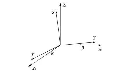
Fig.1 Mechanism of installation error angle
1.2 Installation error modeling
After electronic compass is mounted on the carrier, generally there are two misalignment angles. Firstly, giving an assumption that there exists a single installation error angle, by analyzing the influence of this error on magnetic data, a measurement method for a single installation error angle is proposed. Based on this method, the method for two installation error angles can be derived. Considering a signle installation error angle, the relationship between three measurement axes and those of the carrer coordinate system is shown in Fig.2.
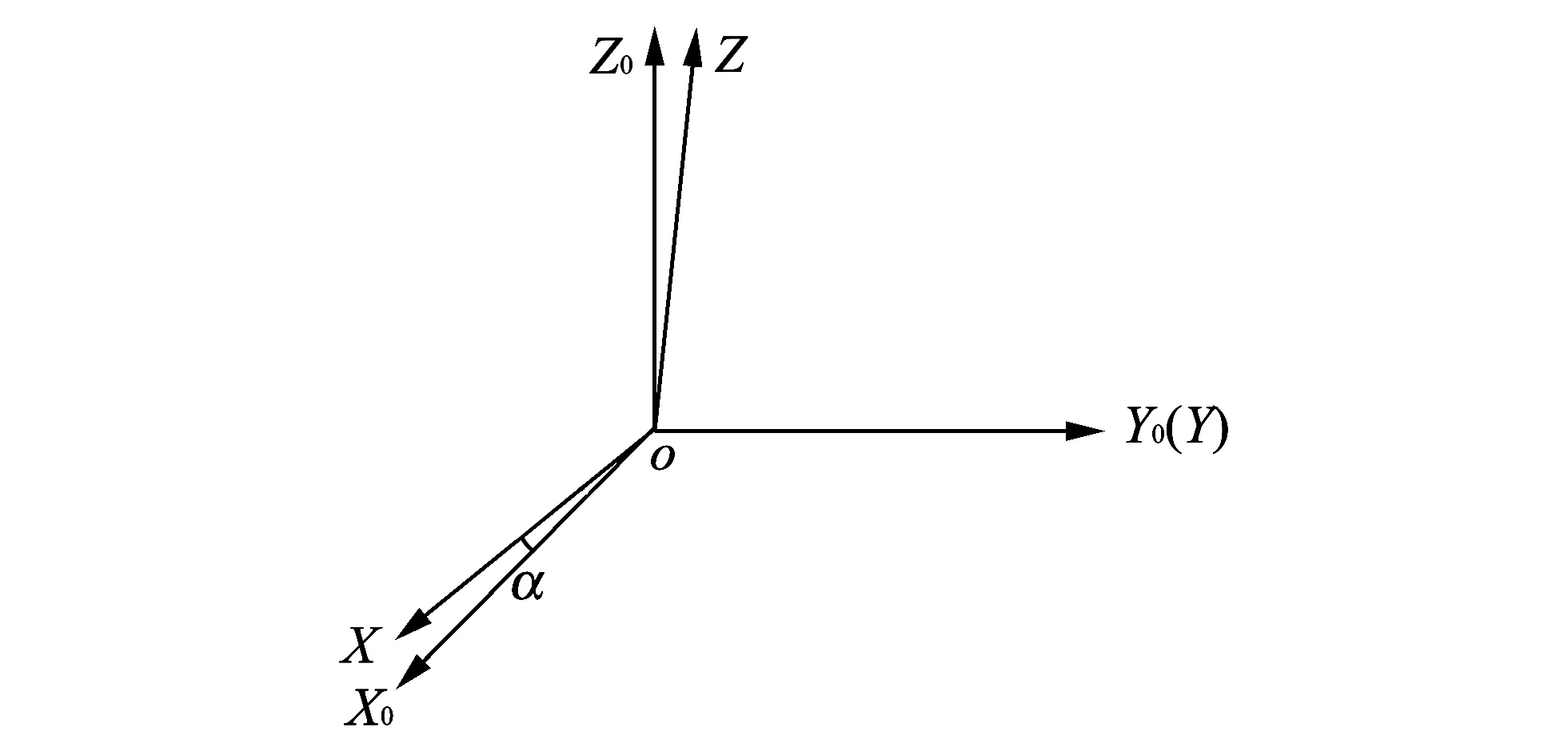
Fig.2 Single installation error angle

When there are two installation error angles (see Fig.1). Only considering installation error, the coordinate transformation from OXYZ to OX0Y0Z0can be achieved as follows. OXYZ rotates around X axis and Y axis for angle α and β, respectively, and then vector coordinates OX0Y0Z0is got.
Coordinate transformation equation is
Misalignment angles are determined after the electronic compass is installed on the carrier. If the installation error angles α and β can be accurately calibrated, the measured output values of electronic compass can be compensated well. Generally, installation error angles are in the range of ±20′, which are very small. Therefore, by simplifying Eq.(1), the installation error compensation equation can be written as
1.3 Solution of misalignment angles
Because the installation error angles are very small, one of the two angles, α or β can be ignored firstly, then the other angle is solved. When there exist two installation error angles simultaneously, magnetic field strength in the directions of X and Z on XOZ plane is distorted from a straight line not in parallel with X axis into an ellipse, which is axisymmetric about the line. The distortion is caused by another installation error angle, so one misalignment angle can be solved using the above described method by ignoring another misalignment angle with least square fitting method.
1.4 Simulation analysis
To verify the correctness of the method for solving misalignment angles, a theoretical simulation experiment is conducted. Assume that the three-axis magnetic field strength measured in the horizontal direction is from 134.845 43 T to 0.171 86 T, when there are two misalignment angles: α=5°, β=10°, after rotating for a circle, the three-axis magnetic field strength is shown in Fig.3.
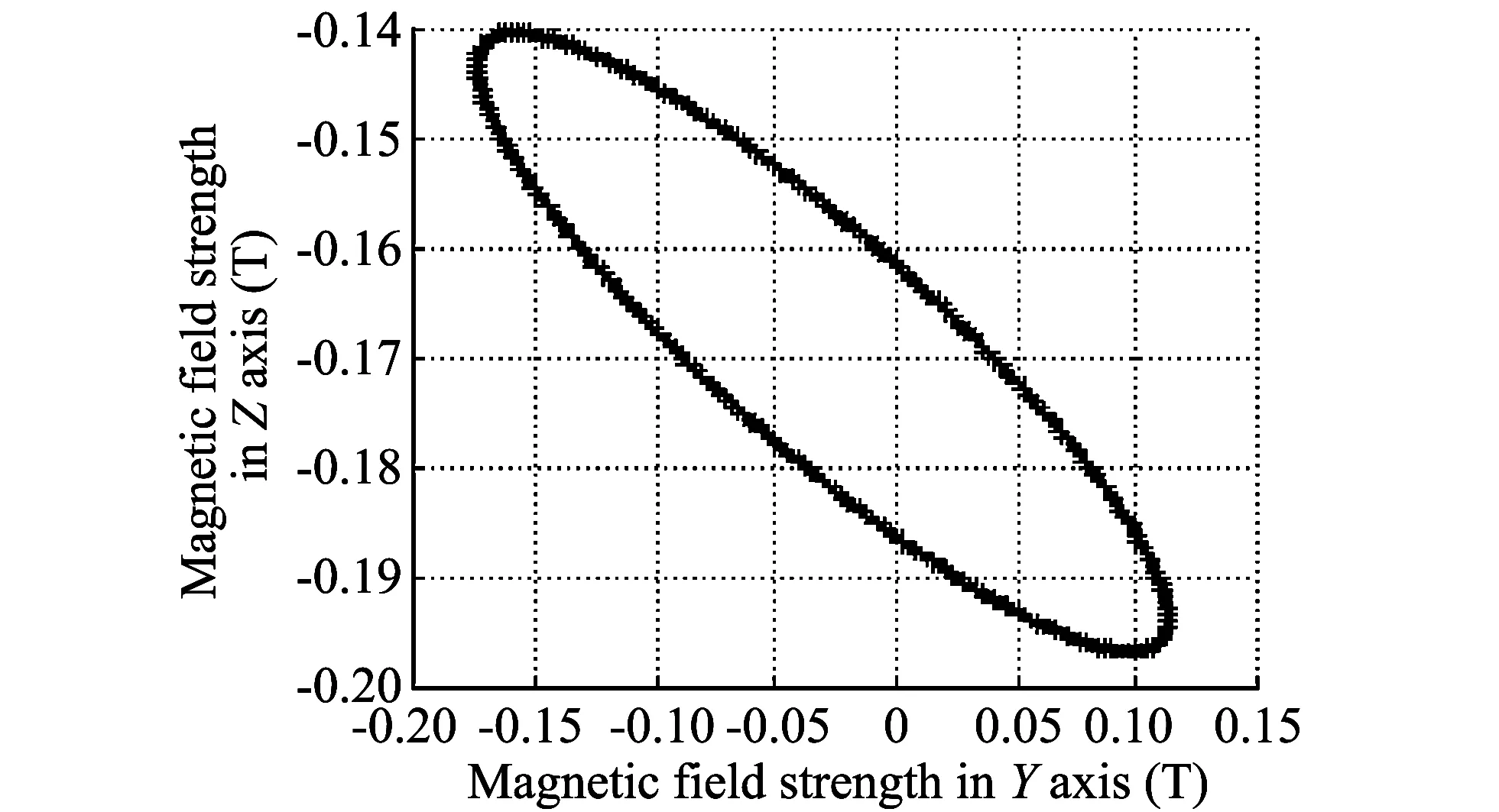
Fig.3 Three-axis magnetic field strength
It can be seen from Fig.3 that the magnetic field strength on XOZ plane changes from a straight line in parallel with the abscissa to an ellipse. Through fitting misalignment angles with least square fitting method, α and β can be got: α1=4.924 4°, β1=9.923 7°, which are close to the values set in advance. Compensating the magnetic data for installation error angles based on Eq.(2), the new magnetic data is got. Simlarly, using the above method to solve the second installation error angle, the results are: α2=0.075 6°, β2=0.076 0°. The two fitting results add together, the final installation error angle are α=5°, β=9.999 7°, which substantially are equal to the predetermined installation error angle. Three-axis magnetic field strength of installation error angle after compensation is drawn in Fig.4.
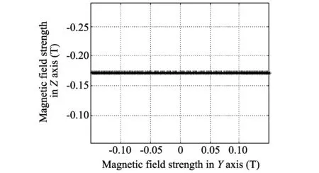
Fig.4 Three-axis magnetic field strength after compensation
As shown in Fig.4, the magnetic data after the compensation for misalignment angles coincide with the original data. In the direction of Z axis, the magnetic field strength remains unchanged, which indicates that the method to solve installation error angle is correct and effective.
2 Calibration of misalignment angles
2.1 Discussion on calibration plane
The derivation of the above described method is based on the assumption that the carrier rotates in the horizontal plane. But in practical operation, implementation of the method is limited due to the horizontal plane. It needs to be discussed that whether the method can be used in any plane to calibrat and calculate the misalignment angles.
Suppose that three measurement axes are pairwise orthogonal and there are no sensitivity error and bias error. No matter carrier is in any plane, installation error between the electronic compass and carrier will not exist. When the electronic compass rotates 360°around Z axis, magnetic field component in the direction of Z axis is unchanged because Z axis is always have an angle of 90° with the plane. Magnetic field components in the X axis and Y axis directions are the sinusoidal, and the two axes are mutually orthogonal. It is similar to the case the carrier is mounted on the horizontal plane. When there exist misalignment angles, the carrier rotates for a circle, the corresponding 3D magnetic filed strength changes from a straight line distribution in the XOZ and YOZ planes to an ellipse, which is similar to the variation of the carrier magnetic field strength in the horizontal plane. Thus installation error angle calibration and calculation methods proposed in this paper are applicable in any plane.
2.2 Design of calibration scheme
1) Select the relatively clean magnetic environment and an arbitrarily plane. Electronic compass is rotated for 360° in the plane, the magnetic field strengths in three-axis directions can be acquired.
2) According to the magnetic field strengths in both directions of Y and Z, using the least square method to fit the slope of straight line, β1is calculated.
3) α1is calculated according to magnetic field strengths in the directions of X and Z.
4) According to Eq.(2), the installation error angle compensation is calculated and the installation angle errors α2and β2are calculated again.
5) Final calculated misalignment angles are α=α1+α2, β=β1+β2.
6) 3D magnetic field strengths after compensation are calculated.
The installation error angles solved by least square fitting method is an approximation of the actual values, and this progressive approximation method can be used for accurate calibration. The obtained misalignment angles can be compensated again. After several calculations and compensations, the calculated misalignment angles can infinitely approach to the actual installation error angles.
3 Experiments and results
In order to verify the correctness and validity of the installation error angle calibration and compensation methods, HMC3300 is used to conduct the verification experiment. The installation error produces when electronic compass is fixed to the plane, because the plane formed by X axis and Y axis is not parallel with actual plane. With the above described method, electronic compass installation error angle calibration tests in different inclination planes are carried out, the results are shown in Table 1.
In Table 1, the calibration results of installation error angles in planes 1 to 3 are basically the same, but in plane 4, they are quite different from those in other planes.
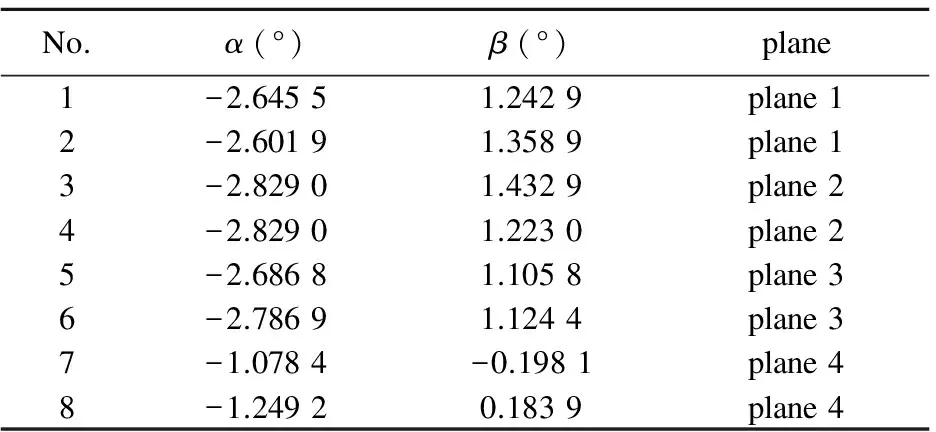
Table 1 Installation error angle calibration results
It can be seen that the changes in magnetic field strength in plane 4 are significantly less than the remaining three groups of measurement results, and the absolute values of the magnetic field strength in the direction of Z axis are greater than the other three groups.
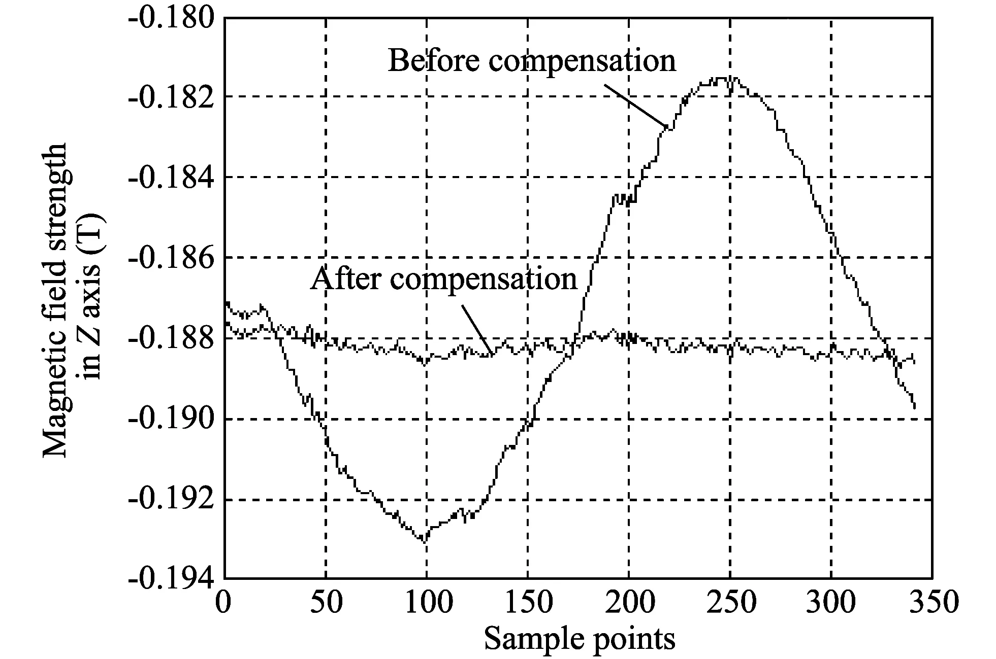
Fig.5 Magnetic field strengths before and after compensations
When the calibration plane is parallel to the geomagnetism vector, the magnetic field vectors in X axis and Y axis directions are close to zero. Rotating for a circle, because the change of magnetic field strength caused by installation error is close to the measurement error of the sensor itself, the changes of magnetic field strength can not reflect the changes of the magnetic field strength of each axis caused by installation error angle. The reason is that plane 4 is nearly parallel to the geomagnetic vector field, resulting in that the installation angle error has a bias. Similarly, when the calibration plane is perpendicular to the ground magnetic field vector, since there is a small change of magnetic field vector in the direction of Z axis, the obtained installation error angle will also have a certain bias compared with the actual one. Therefore, the calibration plane preferably has an inclination angle of 45°. In this case the installation angle deviation error measured is the smallest. The misalignment error angle after calibration in plane 1 is selected to compensate, the result is shown in Fig.5. It can be seen from Fig.5, after the compensation, the variation of the magnetic field strength in the direction of Z axis decreases, so compensation effect is obvious.
4 Conclusion
Calibration and compensation for installation angle error of electronic compass can guarantee measurement accuracy of geomagnetic navigation system. The method mentioned in this paper for installation error calibration is simple and easy to be implemented. So it can be widely used for rapid calibration and compensation for misalignment angles of electronic compass.
[1] DU Ying, LI Jie, KONG Xiang-lei, et al. Error compensation research for electronic compass with non-heading reference,Chinese Journal of Sensors and Actuators, 2010, 9: 1285-1288.
[2] XIAO Chang-han, HE Hua-hui. An analysis method of magnetic field data from the non-idealy placed 3 axial magnetometer sensor. Journal of the Naval Academy of Engineering, 1996, 76(3): 7-12.
[3] LI Ren, CHEN Xi-jun, ZENG Qing-shuang. Error analysis of rotating strapdown inertial navigation system. Journal of Harbin Institute of Technology, 2010, (3): 368-372.
[4] CHEN Guang, SUN Zhi-liang, SUN Hai-zhu. Curve fitting in least-square method and its realization with Matlab. Ordnance Industry Automation, 2005, (3): 107-108.
[5] LI Shu-hua, SHAO Yong. Application of digital compass HMR3000 in the vehicular equipment. Electro-Optic Technology Application, 2010, 25(3): 13-17.
[6] YAN Bei, WANG Bin, LI Yuan. Optimal ellipse fitting method based on least-square principle. Journal of Beijing University of Aeronautics and Astronautics, 2008, 34(3): 295-297.
[7] LI Qing-de, Griffiths J G.. Least square ellipsoid specific fitting. In: Proceedings of IEEE Geometric Modeling and Processing, Beijing, 2004: 335-340.
[8] Hepner D,Harkins T. Determining inertial orientation of a spinning body with body-fixed sensor. ARLTR-2313, 2001: 7-11.
[9] Grammalidis N, Strintzis M G. Head detection and tracking by 2-D and 3-D ellipsoid fitting. In: Proceedings of IEEE Computer Graphics International, Geneva, Swiss, 2000: 221-226.
[10] Xensor Integration Corporation. Earth magnetic filed sensor XEN-1200. 2007.
date: 2013-09-15
Natural Science Foundation of Shanxi Province (No.2010011022-4)
FAN Cheng-ye (fanchengye125@126.com)
1674-8042(2013)04-0313-04
10.3969/j.issn.1674-8042.2013.04.002
猜你喜欢
杂志排行

Journal of Measurement Science and Instrumentation的其它文章
- A CAWL handler for context-aware composite workflow services
- Movement and behavior analysis using neural spike signals in CA1 of rat hippocampus
- Synthesis and cost estimation of ethylene oxide process using PRO/II
- Efficient model building in active appearance model for rotated face
- Preparation and characterization of TiO2-SiO2-Fe3O4 core-shell powders in nano scale
- Changes in hippocampal neural response by external reward