Study on Pressure Coefficient Distribution of the Airship Zhiyuan-1
2013-09-16PingLiuGongYiFuXiaoLiangWangQiSong
Ping Liu,Gong-Yi Fu,Xiao-Liang Wang,Qi Song
(1.School of Naval Architecture,Ocean&Civil Engineering,Shanghai Jiaotong University,Shanghai 200240,China;2.School of Aeronautics and Astronautics,Shanghai Jiaotong University,Shanghai 200240,China;3.China Academy of Space Technology,Beijing 100094,China)
1 Introduction
A stratospheric airship should be able to maneuver and be geostationary at altitude 20 km for a long-term.To be a airship with huge flexible inflated structure,keeping original shape and maintaining a stable aerodynamic performance under wind flow are one of the technologies[1-3].For the designing,manufacturing and demo flying of a technical demonstrating stratospheric airship,a wind tunnel test on rigid model of the airship Zhiyuan-1 had been carried out in China Aerodynamics Research&Development Center.The test results of aerodynamic characteristics of the Zhiyuan-1 Airship had been introduced[4].And as a continuous introduction of the wind tunnel test,the results of pressure coefficient distributions are described in this paper.
2 Test Model
The hull configuration of the airship Zhiyuan-1 is based on the optimism of Michel Transition Law[5-6].The slenderness ratio of the hull is 3.3[7],25 m in length,750 m3in volume and 480 m2in hull surface.Maximum radius of transverse section of the hull is 3.79 m in the distance 9.84 m from airship nose;the floating center of the hull is located at 12 m away from the airship nose.Generatrix of the hull is referred by Fig.1.The gondola with semi-circular front fairing to reduce aerodynamic drag is suspended at the button of the hull.Two propellers are installed on the left and right side of the gondola respectively,and one propeller is at the empennage of the hull.Besides a cross type of fins is adopted[8-9].
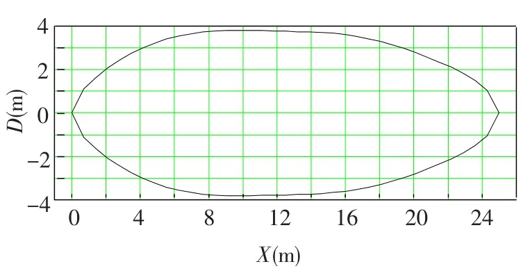
Fig.1 Generatrix of the hull
The wind tunnel is an opening and closing of dualuse,return-type wind tunnel,and the test is carried out in the open section.The test section is a circle shape,diameter in 3.2 m,length in 5 m,with a maximum wind speed of 115 m/s and average flow angle of less than 0.5°.For this test,wind velocity set in 70 m/s.
Based on the similarity criteria and test condition[10-11],geometry parameter of the model is referred in Table 1.

Table 1 Geometry parameter of the test model
To compare the effect of surface roughness of the hull,test conditions are divided into having or no turbulence strips condition.At the front,middle and back of the hull,turbulence strips are installed to simulate roughness of the hull,as shown in Fig.2[12].

Fig.2 Test conditions
3 Pressure Tap Lines Arrangement
The major measure content includes:the force and the pressure distribution of hull,tail,and gondola configuration respectively.In each configuration,different combinations of yaw angle and pitch angle are considered.The pressure tap lines are set as follows(referred as Fig.3):
1)Along the hull(x-y plan),40 pressure taps are set up in 4 lines of which inclining 45° and 135°on the hull surface respectively,and represented by symbols YS,YX,ZS,ZX as shown in Fig.3.
2)At the 703 mm from the nose of hull and 270 mm from the aft of the hull,24 pressure taps are set up in lines around the hull surface respectively.
3)On front of gondola,22 pressure taps are set up in two horizontal lines respectively,and represented by the symbols of Q and H.
4)A total of 60 pressure taps are set up in three lines on the left-fin and up-fin respectively.

Fig.3 Pressure tap lines arranged on the test model
4 Test Results of Pressure Coefficients Distribution on the Airship
4.1 Influence of Configuration along the Hull
At the combinations of the pitch angleα=0° and 20° with the yaw angleβ=0°,-20° and 20°(αis pitch angle andβis yaw angle)respectively,the pressure coefficient distribution(Cp)curves of ZS and ZX under fin and gondola configurations without turbulence strips are shown in Fig.4,here,the configurations are named as Hull,Fin,and Gondola,to describe three kinds of configurations of hull only,hull with fins and hull with fins and gondola respectively in the figures below.According to the trend of the pressure coefficient distributions,the pressure coefficients on the nose of the hull are in positive,whose heading is towards the wind;on the middle of the hull,the wind pressure coefficients are in negative;on the aft of the hull,the sign of the pressure coefficients depends on the pitch angle.
A good consistency of the wind pressure coefficient curves are shown under three configurations in the same pitch angle(α=0° and 15°)and zero yaw angle(β=0°)in Figs.4(a)and 4(b).The effect of gondola is obviously seen from the pressure coefficient distribution curves of ZX according to the sudden change of the pressure curves at 600 mm away from the nose of the hull.And no evidence is shown the effect of fins to the pressure coefficient distribution along the surface of the hull.
As the pitch angle increases toα=20°,the pressure coefficient curves in the fin configuration keep the coincidence with that in the gondola configuration even if the yaw angle changed(-20°,0° and 20°)as shown in Figs.4(c)and 4(d).It implies that the fins and the gondola have little effect on the wind pressure coefficient distribution on the hull.

Fig.4 Pressure coefficient distribution in different configuration of airship
4.2 Influence of Pitch Angle along the Hull
The pressure coefficient distributions of the gondola configuration under the attitude of yaw zero(β=0°)and pitch angle range from 0° to 30°(α=0°,15°,30°)are shown in Fig.5.When pitch angle is zero(α=0°),the positive pressure appears on the nose and the aft of the hull,and the negative pressure on the middle of the hull.Turbulence strips(with the symbols of Y in figures)has obviously effect on the pressure distribution near the gondola,but other parts of the hull.
When airship flies with pitch angle,negative area of the pressure coefficient on the hull increases as tunnel test results are shown in Fig.5,which will cause negative pressure of the hull over the designed pressure limit.The change of pressure distribution of ZS,ZX will cause additional moment on the hull,which would cause the change of wind load on the hull and affect flying stability[13-14].
The wind pressure coefficient distributions of ZS and ZX of the gondola configuration with different pitch angle and constant yaw(β=±20°)are shown in Fig.6.When the yaw angle is negative and pitch angle increases,the value of pressure coefficient of ZS will decrease(Fig.6(a)),but that of ZX increases(Fig.6(b)).When the yaw angle is positive,the change of the pressure coefficient distribution of ZS,ZX appears mainly in middle section of hull;and the value of pressure coefficient of ZS(Fig.6(d))will increase and that of ZX(Fig.6(e))decreases as the pitch angle increases.

Fig.5 Pitch effect on the pressure coefficient distribution

Fig.6 Pressure coefficient distribution with constant yaw angle
4.3 Influence of Configuration on the Circumference of the Hull
The pressure coefficient distributions on circumferential surface of the hull in the attitude of(α=0°,β=0°)are shown in Figs.7(a)and 8(a).And that of hull in the attitude of(α=15°,β=0°)are shown in Figs.7(b)and 8(b).
For the configuration of the gondola in the attitude against the wind(α=0°,β=0°),a pinnacle on the pressure coefficient distribution appears at the front point of gondola,because of the geometric change on the surface of the hull(Fig.7(a)),but at any other sections the pressure coefficient distribution keeps consistent basically.At the aft of the hull,the pressure coefficient distribution with four pinnacles at roots of fins is shown in Fig.8(a).
With the increase of the pitch angle,the pressure coefficient distribution on the front circumferential of the hull is changed to a curve like sine wave(Fig.7(b)).The maximum negative pressure coefficient appears at the dorsum and the abdomen of the hull.At the aft of the hull(Fig.8(b)),there is positive pressure on the dorsum of the hull and negative pressure in abdomen.On the both configuration of fin and gondola,a distinct effect on the pressure coefficient distribution is caused by the fins obviously,as four pinnacles appears on the roots of fins,and the maximum values of pressure coefficient of pinnacles are almost the same with attitude of(α=0°,β=0°).
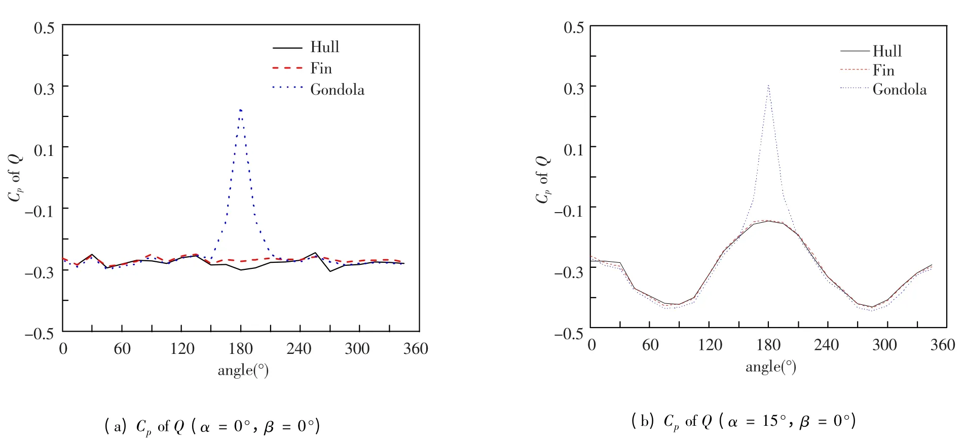
Fig.7 Pressure coefficient distribution of Q(α=0°,15°,β=0°)
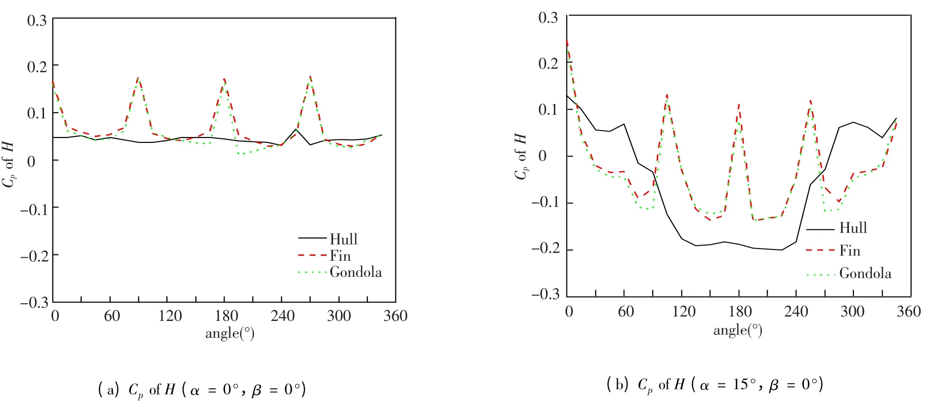
Fig.8 Pressure coefficient distribution of H(α=0°,15°,β=0°)
4.4 Influence of Pitch and Yaw on the Circumference of the Hull
The pressure coefficient distributions on the front circumference of the hull in the attitude of pitch angleα=20° and yaw angleβ=±20° with the fin and gondola configuration are shown in Fig.9(a).Curves just like sine wave appears and local effect of the gondola on the pressure coefficient distribution is shown according to the comparison results with the distribution curves of the fin configuration and gondola configuration.
The pressure coefficient distributions of the gondola configuration are shown in Fig.9(b)with the pitch increase and the yaw keeping at angle 20°.The phase angles of curves are different as the pitch angle changes.
With both of fin and gondola configuration,four pinnacles appear on the roots of fins at any angles of pitch and yaw,and suctions appear on the areas between fins(Fig.10).By the comparison with the pressure coefficient distributions of fin and gondola configuration,the pressure coefficient distributions at the aft circumference of the hull are not affected by the gondola.

Fig.9 Pressure coefficient distribution of Q

Fig.10 Pressure coefficient distribution of H(α=0°,β=0°,±20°)
5 Conclusions
Extensive analyses about wind-tunnel test were performed for the Zhiyuan-1 airship.Through the experimental results of different configuration and flow conditions,the important conclusions can be obtained as follows:
1)A wind tunnel test had been carried out in this paper to investigate the aerodynamics behavior of technical demonstrating stratospheric airship Zhiyuan-1,and the test model is in meeting with the principle of geometric and Reynolds number similarity.The fins and gondola only have the effect on some local area about the pressure distribution and all pressure in other field almost may not be affected with affiliated units.Besides,the turbulent strip has little effect on pressure distribution.That means that airship may treat as a bare hull in process of pressure calculation.
2)A style of pressure-suction-pressure of pressure coefficient distribution along the longitudinal of the hull is presented in the attitude of against wind flow;the pressure coefficient distribution at the front circumference of the hull appears in sine wave,and pinnacles of the pressure coefficient distributions on the aft circumference of the hull appear at the fins roots.
3)The pressure coefficient distribution is discussed according to different configurations of airship,different pitch and yaw angles,and the local effects of fins and gondola to the pressure coefficient distribution are indicated.
[1]Tischler M B,Ringland R F,Jext H R.Heavy-lift airship dynamics.Journal of Aircraft,1983,20(5):425-433.
[2]Zheng Z W,Huo W,Wu Z.Trajectory tracking control for underactuated stratospheric airship.Advances in Space Research,2012,50(7):906-917.
[3]Bennaceur S,Azouz N.Contribution of the added masses in the dynamic modelling of flexible airships.Nonlinear Dynamics,2012,67(1):215-226.
[4]Wang X L,Fu G Y.Experimental investigations on aerodynamic characteristics of the Zhiyuan-1 Airship.Journal of Aircraft,2010,47(4):1463-1468.
[5]Thomas L,Smith W.Drag reduction and shape optimization of airship bodies.Journal of Aircraft,1998,35(3):345-351.
[6]Wang H,Song B,Zuo L.Effect of high-altitude airship’s attitude on performance of its energy system.Journal of Aircraft,2007,44(6):2077-2080.
[7]Gang A W,Li W J,Wang H F.Multi objective certain ptimization design of envelope shape of airship with eviations considered.Journal of Northwestern PolytechnicalUniversity,2007,25(6):789-793.
[8]Melanson M R,Chang M,Baker W M.Wind tunnel testing's future:a vision of the next generation of wind tunnel test requirements and facilities.Proceedings of the 48th AiAA Aerospace Sciences Meeting Including the New Horizons Forum and Aerospace Exposition.AIAA.2010.288-295.
[9]Christa J,Simpson M,Evans F.Fish-like propulsion of an airship with planar membrane dielectric elastomer actuators.Bioinspiration&Biomimetics,2010,5(2):026007.
[10]Ramsden M,Liu P Q,Li Y,et al.Numerical simulation study on aerodynamic characteristics of propeller for the stratospheric airship.Proceedings of the 2011 International Conference on Aerospace Engineering and Information Technology.Beijing:Int Industrial Electronic Center Publisher Ltd,2011.371-376.
[11]Liu P Q,Ma R,Duan Z Z,et al.Ground wind tunnel test study of the propeller of stratospheric airships.Journal of Aerospace Power,2011,26(8):1775-1781.
[12]Alcott R J.Statistical wind analysis for near-space applications.Journal of Atmospheric and Solar-Terrestrial Physics,2007,69(13):1485-1501.
[13]Fang C,Wang W.Dynamics modeling and control of horizontal displacement for unmannea airship.Control Theory&Applications,2007(2):161-169.
[14]Hu G C,Wu M P,Zhang Y.Summarization of airship’s attitude control and station-keeping control methods.Materials Science and Information Technology.Stafa,Zurich:Trans Tech Publications Ltd,2012.6890-6895.
杂志排行

Journal of Harbin Institute of Technology(New Series)的其它文章
- Slip Detection of Robotic Hand Based on Vibration Power of Pressure Center
- An Ant Colony Algorithm Based Congestion Elusion Routing Strategy for Mobile Ad Hoc Networks
- Robust Audio Blind Watermarking Algorithm Based on Haar Transform
- Research of Multiagent Coordination and Cooperation Algorithm
- Impact of Online Community Structure on Information Propagation:Empirical Analysis and Modeling
- Prediction of Aircraft Engine Health Condition Parameters Based on Ensemble ELM