Hardware Implementation and Simulations of Joint Coding and Modulation Diversity MIMO-OFDM Scheme
2013-09-16XiangGaoZhanJiWuLongFeiHuaJunPengLiu
Xiang Gao,Zhan-Ji Wu,Long-Fei Hua,Jun-Peng Liu
(School of Information and Communication Engineering,Beijing University of Posts and Telecommunications,Beijing 10086,China)
1 Introduction
Orthogonal frequency division multiplexing(OFDM)has a high spectrum efficiency and capability to mitigate the side-effect of frequency selective fading.Multiple input multiple output(MIMO)can easily achieve the spatial diversity gain and capability gain of wireless channels,so as to significantly improve the spectral efficiency and link quality.Because of these properties,OFDM and MIMO have become the core technologies of the advanced wireless transmission,and the combination of them is the trend of the future of wireless communications.
In order to obtain greater MIMO channel capacity,layered space-time(LST)architecture is proposed by Foschini[1].Through serially concatenating of encoder,bit interleaver and modulator,Bit-interleaved coded modulation(BICM)greatly improves the diversity gain and coding gain[2].Currently,BICMLST is the mainstream technology to overcome MIMO fading channel.The MIMO-OFDM scheme based on BICM has been adopted by many wireless communication standards,such as 3GPP LTE and IEEE 802.11n[3-4].
A modulation diversity scheme based on rotational multi-dimensional constellation for single input single output(SISO)system was proposed[5].It verified tremendous performance advantage of modulation diversity in Rayleigh fading channel.However,their study focused on uncoded single antenna system.On this basis,we extend modulation diversity technique to the coded OFDM systems[6].Through the rotational modulation and designed component interleaver in timefrequency domain,the proposed scheme presents significant performance advantages.Furthermore,we propose an improved coded rotated modulation OFDM scheme based on the iterative demodulation/decoding(ID)scheme and extend the four-dimensional coded modulation diversity as well[7].At present,the research about modulation diversity technology has received a lot of achievements[8-12],but mainly stays in a stage of theoretical analysis and software simulations.However,there is still a large gap between the theoretical analysis and practical implementation.
A joint optimization method of channel coding and two-dimensional modulation diversity applied in MIMOOFDM system named Joint Coding and Modulation Diversity(JCMD)is proposed which further extends the modulation diversity to the spatial domain.This paper focuses on the hardware implementation of the proposed scheme and the related simulation results.The proposed scheme can take full advantage of coding gain of channel coding and the spatial-time-frequency diversity of MIMO-OFDM system all together.The selfdeveloped hardware prototype system verifies the practicality and robustness of the proposed scheme.Software and hardware simulation results show that it can achieve a performance much better than that of the conventional BICM MIMO-OFDM system and is more suitable for high data rate transmission.
2 System Model
The BICM-MIMO-OFDM scheme,which is widely used in many communication standards,is given in Fig.1(a).On this basis,through the replacement of conventional modulation with rotational modulation and design of spatial and time-frequency Q-component interleaver,the proposed JCMD-MIMO-OFDM scheme is constituted,as shown in Fig.1(b).
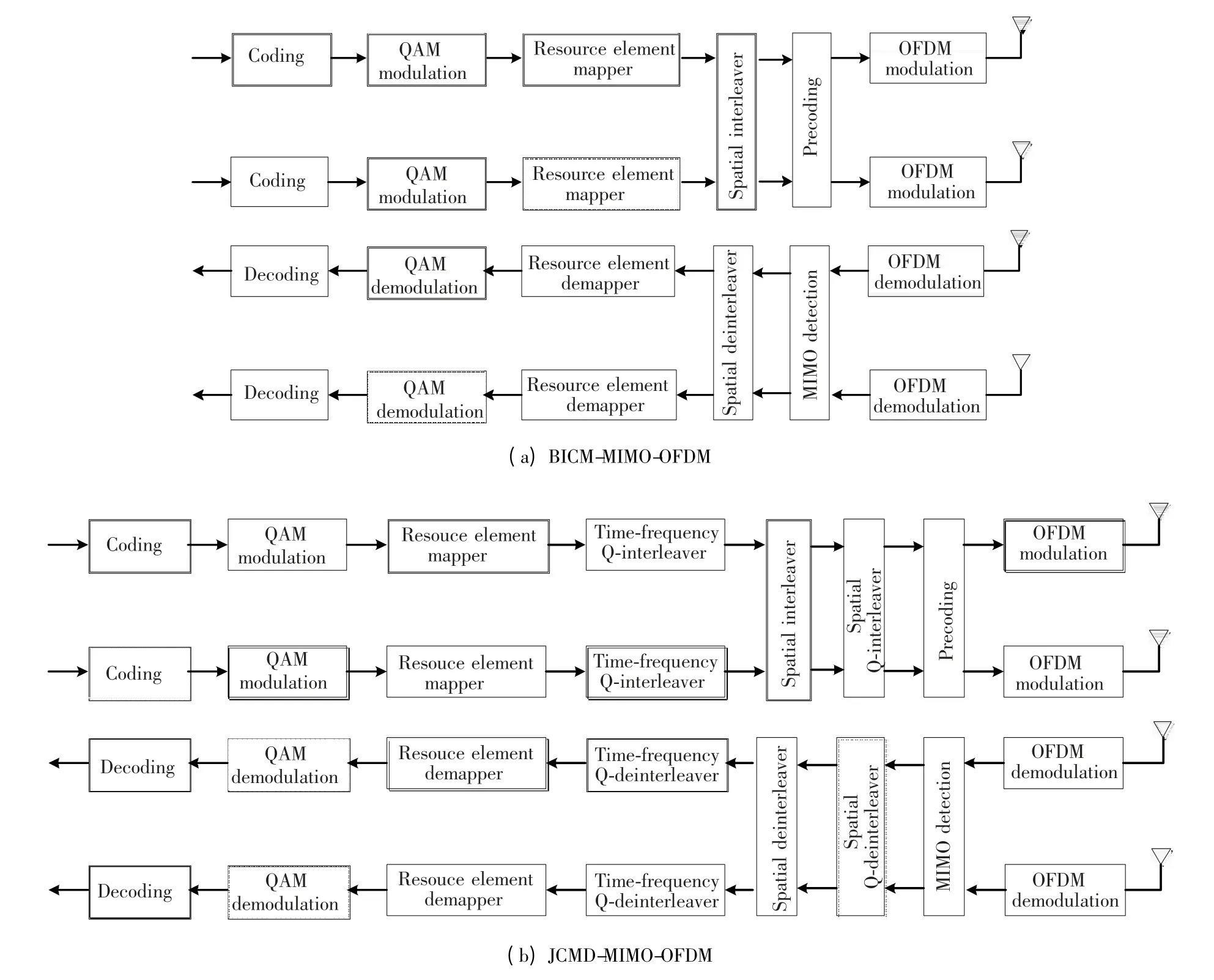
Fig.1 Comparison between BICM-MIMO-OFDM and proposed JCMD-MIMO-OFDM scheme
Threaded layered space-time(TLST)architecture[13]is adopted in the proposed scheme.For presentational convenience,we assume MIMO-OFDM systems with NLtransmit layers,NTtransmit and NRreceive antennas.In each frame,each user occupies L sub-carriers in the frequency domain and NSOFDM symbols in the time domain.In the transmitter of JCMD-MIMO-OFDM scheme,the information bits sequence is encoded separately on each transmit layer.According to the selected optimal rotational matrix,coded bits are modulated into complex-valued symbols via rotational modulation.For each layer,complexvalued modulated symbols are mapped onto OFDM subcarriers in each of the OFDM symbols via the resource element mapping function.We denote the Qcomponent of the modulated symbol which is mapped on the fthsubcarrier in the tthOFDM symbol as Q(f,t).For the Q-components,time-frequency Q-interleaving is performed resulting in the output Q(f',t'),according to the rule as follows:

Afterwards,the symbols on all the layers are rearranged by the spatial interleaver of TLST scheme,which generally can be provided by the cyclic shift interleaver.Symbol on the ithlayer at time sample t is denoted byThe interleaving is defined by the rule as shown in Eq.(1).

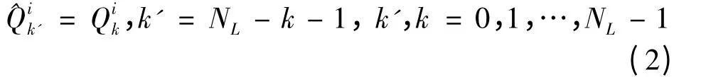
The spatial Q-component interleaving is conducted after the spatial interleaving.The main purpose of time-frequency Q-component interleaving is to make Iand Q-component of complex-valued modulated symbols not to be related in time and frequency domain as much as possible.Thanks to the spatial advantages of MIMO,the independence of the different components can be extended to the spatial domain via spatial Q-component interleaving.The Q-component of ithsymbol on kthlayer is defined as.Correspondingly,the output of spatial Q-component interleavingcan be calculated as Eq.(2).
After the precoding,convert the subcarriers to time domain using NFFT-points IFFT and insert cyclic prefix(CP)for each of the transmit antennas.
In the receiver,OFDM demodulation is carried out firstly,including removing CP and FFT.And then,MIMO detection is performed in frequency domain.After a series of inverse performance including spatial Q-deinterleaving,spatial deinterleaving,timefrequency Q-component deinterleaving and resource element demapping,each symbol uses the maximum likelihood(ML)criterion for rotational demodulation processing to produce the Log-likelihood-ratios(LLRs)of encoded bits.According to the LLRs,the information bits are decoded via decoder.
The proposed scheme basically extends the traditional process flow of BICM MIMO-OFDM.Through the addition of interleavers,it not only makes the best use of spatial,time and frequency diversities,but also gives consideration to the compatibility and scalability with conventional transmission scheme.
3 Modulation Diversity
The rotational modulation is a simple means to obtain the modulation diversity.Through the combination of rotating the conventional constellation with independent interleaving of the rotated symbol components,data to be transmitted are diffusely distributed to the different components,so that the signal diversity can be achieved to improve the performance in fading channels.
Typically,a n-dimensional rotational constellation points can be obtained by multiplying the conventional QAM constellation points x with rotational matrix R.The modulation diversity order L of a multidimensional signal set is the minimum number of distinct components between any two constellation points.Maximizing the diversity order L is an effective way to improve system performance.
To take 2-dimensional rotational QPSK as an example,pair of successive bits ki,k(i+1)are mapped to a complex-valued symbol di=Ii+j·Qiaccording to the conventional QPSK constellation set as shown in Fig.2(a).According to optimum rotation angleθ,diis rotated to generate a new complex-valued symbol d'i=Xi+j·Yias shown in Fig.2(b).This process can be expressed as

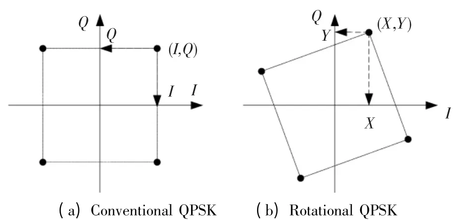
Fig.2 Comparison between conventional QPSK and rotational QPSK constellation set
As shown in Fig.2,for the conventional QPSK,every two bits are mapped to a complex-valued symbol.The information of each bit is carried by I-and Qcomponent independently.That is to say,any two adjacent constellation points have an identical component.So the diversity order of conventional QPSK constellation set is 1.In contrast with the conventional QPSK,transmit information is spread over the different components of rotational QPSK constellation.In this case,the I-and Q-components of any two constellation points are not the same,thus the diversity order increased to 2.The diversity gain will be achieved as long as that the fading coefficients of the different components are uncorrelated.Component interleaver is a simple and effective method to guarantee the independence of different components of the rotational modulation symbols.Therefore,rotational modulation is applicable to fading channel.The performance of the rotational QPSK constellation is identical to that of a conventional QPSK constellation in Additive White Gaussian Noise(AWGN)channel.In addition,the enhancement of system performance also relies on the design of component interleaver.For the proposed component interleaver which is introduced in section 2,with the advantage of time-frequency structure of OFDM and spatial structure of MIMO,the independence of the I-and Q-components can be ensured in time,frequency and spatial domain.
It is worth noting that the transmit power of conventional modulated symbol and rotational modulated symbol remain unchanged,because the rotation matrix R is orthogonal unitary matrix.In practical applications,rotational modulation can be implemented through look-up table mapping as the same as the conventional modulation.Therefore,compared to conventional modulation,the rotational modulation will not increase the complexity and delay of processing.
The selection of the optimal rotational angle is one of the key issues which needs to be considered to maximize the anti-fading ability.A criterion of the optimal angle for uncoded system in Rayleigh fading channel was proposed in Ref.[5].However,the criterion is only applicable to the case of high signal-tonoise ratio(SNR).For coded system,due to the channel coding significantly reduce the operating SNR range,so the optimal rotational angle applied to the proposed system is different from that.
The optimal rotation angle is selected by the method so that the projection of both components of the rotational constellation point can be located in each axis as scattered as possible.Numerous simulation results indicate that the optimal angle of coded system is primarily associated with the coding rate and modulation order,and has little to do with the channel model,simulation scenarios and other factors.The rotational angle and the code rate are weak-related,especially for the high code rates,optimal rotational angle has a good robustness.However,it strongly correlates with the modulation order.For the same rate under the conditions of different modulation orders,the optimal rotational angle decreases with the increase of modulation order.The optimal rotational angle for coded OFDM system was studied in Ref.[6].For 22k-QAM,the optimal rotational angle is aboutθ=arctan(1/2k).
4 Detection and Demodulation
In the receiver,minimum mean-squared error(MMSE)detection is performed after FFT calculation.The advantage is that detection in frequency domain is more simple and intuitive[14-15].
MIMO systems can benefit from significant diversity and coding gains by using precoding.In our simulations,codebook-based precoding scheme is used.In the receiver,according to the estimated channel state information(CSI),performance indicators(SINRs)of each precoding matrix in the codebook[3]are calculated to determine the appropriate precoding matrix.The index of the selected appropriate precoding matrix should feedback to transmitter for precoding.
The precoderin the transmittertakes a vector xi=as inputand generatesa vectorsyi=to be mapped onto each transmit antenna port,whererepresents the symboli on layerp,andrepresentsthe symbol i on antenna port p.Precoding isdefinedbyEq.(3).

where Piis the precoding matrix corresponding to the ithtransmit symbol vector.The values of Pishall be selected among the precoder elements in the codebook according to the feedback precoding matrix index(PMI).
If procoding is not adopted,Piis the identity matrix.Let ri=denote the received signal vector on NRantenna ports,which can be expressed as follows:

where H is the NR×NTMIMO channel matrix;ni=denotes a AWGN vector on antenna ports with mean zero and variance
In the receiver,MMSE detection matrix can be defined as,whereis the ratio of noise power to signal power and I is a NL×NLunit matrix.Thus,the output vector of MMSE detector si=is shown as follows:

where A=W·K is a NL×NLmatrix,and Aklis the element on the kthrow and the lthcolumn.Likewise,Wklis the element of W on the kthrow and the lthcolumn.For the ithsymbol on receive layer p,

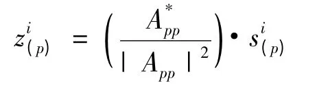
After the MMSE detection,in order to simplify the demodulation,the phase compensation is carried to overcome the phase distortion as follows:
Assuming the transmit signal power=1,signal to interference plus noise ratio(SINR)for symbol i on receive layer p is estimated as follow:

After the phase compensation,spatial Qdeinterleaving,spatial deinterleaving,time-frequency Q-component deinterleaving and resource element demapping are performed sequentially.Afterwards,the rotational demodulation is carried out on each layer according to ML criterion.The ithreceived complexvalued symbolis considered.For the proposed scheme,the SINRs of I-and Q-component of Riare different,which are noted asand,respectively.The LLR of bitwhich is the xthbit of Riis calculated according to Eq.(4).


5 Hardware Imp lementation of JCMD-M IMOOFDM Scheme
In order to further validate the realization of the proposed scheme and the performance advantages compared to the conventional BICM-MIMO-OFDM scheme,we use the R&S precision instruments including the signal analyzer FSV,channel simulator AMU and vector signal generator SMVB to self-develop the 2×2 MIMO-OFDM prototype.The block diagram of entire platform is shown in Fig.3.
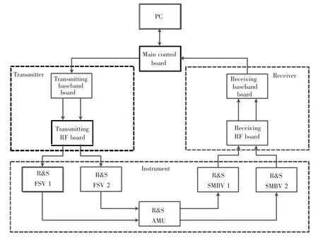
Fig.3 System block diagram of the hardware platform
The complete transceiver link of hardware prototype consists of the transmitter,receiver and instruments.PC and the main control board are connected via Ethernet.The latter's main function is control of the transmitting and receiving baseband board,including code download and timing control.Transmitting board is constituted by the transmitting baseband board and RF board.Baseband board generates and transmits the baseband digital OFDM signal firstly,and then sends the signal to the RF board through optical fiber.Afterwards,digital baseband signal is modulated onto a fixed carrier frequency 2350.4 MHz and transmitted.Variety of wireless channel propagation environments are simulated by channel simulator AMU.Because of the signal processing requirements for channel simulator,the transmitted RF signals should be down-converted to baseband analog signals by the signal analyzer,and then be sampled and sent to the channel simulator.After the fading and noise operation,the output of channel simulator is up-converted to RF signal again by vector signal generator.In the receiver,receiving board is constituted by the receiving baseband board and RF board.Received RF signals are demodulated to the baseband,and then sent to receiving baseband board.After the corresponding receiving processing,PC counts the FER/BER.
Fig.4 Shows the photo in kind of the prototype system.

Fig.4 Chart in kind of the prototype system
6 Simulation Results
In order to verify the performance advantages of the proposed scheme compared with the conventional BICM-MIMO-OFMD scheme,both computer software and hardware simulations are carried out in the same scenario and parameters by fixed-point C simulation platform and self-developed prototype system,respectively.The simulations focus on different moving speeds and procoding schemes.The simulation parameters are listed in Table 1.
6.1 Software Simulations
The software simulation results are displayed in Figs.5 and 6.Fig.5 shows the bits error rate(BER)performance of the proposed scheme and conventional BICM-MIMO-OFDM scheme for the cases of different moving speeds in VA channel model.3/4 code rate and QPSK modulation are adopted.The pilot-based channel estimation technique is used in the system.With the rise of the mobile speed,the Doppler shift increases,resulting in the more dramatic changes of the channel in the time domain.However,the distribution of the pilots is fixed in the system model.Therefore,the overall system performance deteriorates with the rise of the mobile speed as shown in Fig.6.For the case of 60 km/s moving speed,the proposed JCMD-MIMO-OFDM scheme can obtain about 1.4 dB SNR gain compared with the BICM-MIMO-OFDM scheme at target BER=0.01.With the increase of the moving speed up to 200 km/h,the SNR gain also increases to nearly 1.8 dB.Therefore,the proposed scheme can achieve significant performance advantage in various mobile speeds,especially for high moving speeds,SNR gains are more significant.

Table 1 Simulation parameters
The software simulated BER performance of proposed scheme and conventional BICM-MIMO-OFDM scheme that use codebook based precoding is shown in Fig.6.We also consider the case of 3/4 code rate and QPSK modulation.The simulated mobile speed is 30 km/h.For the codebook based precoded system,the SNR gain is about 1.5 dB at target BER=0.01.So,the proposed scheme greatly outperforms the conventional BICM-MIMO-OFDM scheme,both in the case of that the precoding is used or not.
6.2 Hardware Simulations
The same simulations are also performed through the self-developed prototype system to verify the performance of actual system in the conditions of nonideal channel estimation and non-ideal synchronous.The VA channel model is simulated by R&S AMU.
Fig.7 shows the BER performance comparison of hardware simulation for the cases of different mobile speeds.Since hardware simulations are in the conditions of non-ideal channel estimation and synchronous,there are many differences from the software simulations both in calculation accuracy and simulation environments.Hence,the overall performance of hardware simulation deteriorates compared with that of software simulation.It can be seen that the hardware simulation results are in consistent with software simulation results.For the case of 60 km/s mobile speed,the proposed JCMD-MIMOOFDM scheme can obtain about 1.3 dB SNR gain compared with the BICM-MIMO-OFDM scheme at target BER=0.01.When the mobile speed increases to 200 km/s,the SNR gain is more significant.

Fig.5 Software simulation result in VA channel model,3/4 code rate,QPSK,LS channel estimation,BER comparison between JCMD-MIMO-OFDM and BICM-MIMO-OFDM for different speeds
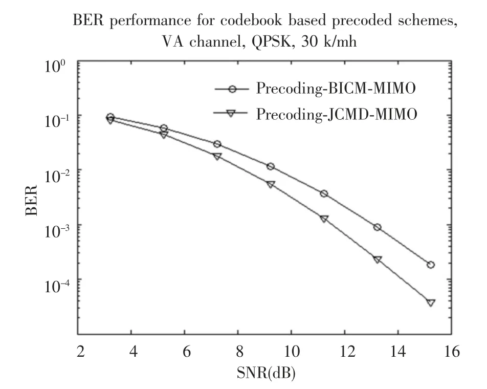
Fig.6 Software simulation result in VA channel model,3/4 code rate,QPSK,LS channel estimation,FER comparison between JCMD-MIMO-OFDM and BICM-MIMO-OFDM for codebook based precoding scheme
Fig.8 shows the BER performance comparison of hardware simulation for codebook based precoding schemes.Likewise,the results of hardware and software simulations are consistent.For the codebook based precoded schemes,JCMD-MIMO-OFDM can obtain about 1.5 dB SNR gain compared with the BICM-MIMO-OFDM at BER=0.01.

Fig.7 Hardware simulation result in VA channel model,3/4 code rate,QPSK,LS channel estimation,BER comparison between JCMD-MIMO-OFDM and BICM-MIMO-OFDM for different speeds

Fig.8 Hardware simulation result in VA channel model,3/4 code rate,QPSK,LS channel estimation,FER comparison between JCMD-MIMO-OFDM and BICM-MIMO-OFDM for codebook based precoding scheme
7 Conclusions
This paper proposes an efficient JCMD-MIMOOFDM scheme and focuses on the hardware implementation of it.The proposed scheme applies modulation diversity to coded MIMO-OFDM system,which can effectively use time diversity,frequency diversity and spatial diversity.Hardware prototype system verifies the robustness and highly reliable of the proposed scheme.The simulation results of software and hardware prototype show that the proposed scheme can achieve significant performance advantages compared with the BICM-MIMO-OFDM in the case of non-ideal CSI,as well as non-ideal synchronization.Especially in the case of a high mobile speed,the SNR gains are more prominent.Both for precoded and nonprecoded system,the proposed scheme can significantly improve the performance.Therefore,the proposed JCMD-MIMO-OFDM is an efficient,achievable and robust transmission scheme which can meet the development requirements of the next generation of wireless communication.
[1]Foschini G.Layered space-time architecture for wireless communication in a fading environment when using multielement antennas.Bell Lads Technical Journal,Autumn 1996,1(2):41-59.
[2]Caire G,Taricco G,Biglieri E.Bit-interleaved coded modulation.IEEE Transactions on Information Theory,1998,44(3):927-946.
[3]3GPP.3rd Generation Partnership Project,Technical Specification Group Radio Access Network,Evolved Universal Terrestrial Radio Access(E-UTRA).Multiplexing and channel coding(Release 10).3GPP TS 36.211,version 10.2.0.Valbonne:3GPP,2011.
[4]Eldad Perahi.IEEE 802.11n development:history,process,and technology.IEEE Communications Magazine,2008,46(7):48-55.
[5]Boutros J,Viterbo E.Signal space diversity:a power and bandwidth efficient diversity technique for the Rayleigh fading channel.IEEE Transactions on Information Theory,1998,44(4):1453-1467.
[6]Wu Zhanji,Wang Wenbo.A novel joint-codingmodulation-diversity OFDM system.Global MobileCongress 2010.Washington,DC:IEEE Computer Society.2010.307-312.
[7]Wu Zhanji,Wang Wenbo.Improved coding-rotated-modulation orthogonal frequency division multiplexing system.IET communications,2012,6(3):272-280.
[8]Lee H.MIMO systems based on modulation diversity.IEEE Transactions on Communications,2010,58(12):3405-3409.
[9]Srinivas K,Koilpillai R.Co-ordinate interleaved spatial multiplexing with channel state informatin.IEEE Transactions on Wireless Communications,2009,8(6):2755-2762.
[10]Xie Qiuliang,Song Jian,Peng Kewu,et al.Coded modulation with signal space diversity.IEEE Transactions on Wireless Communications,2001,10(2):660-669.
[11]Soon U H,Jinyong C,Sungho J,et al.Performace evaluation of MIMO-OFDM with signal space diversity over frequency selective channels.IEEE Internatonal Symposium on Broadband Multimedia.System and Broadcasting.Washington,DC:IEEE Computer Society.2009.1-5.
[12]Wu Zhanji,Fu Tingting,Wang Xu,et al.A novel Coding-Rotated-Modulation OFDM scheme.International Conference on Communication Technology and Application 2009.Washington DC:IEEE Computer Society.2009.517-520.
[13]Vucetic B,Yuan Jinhong,Space-Time Coding.England:John Wiley&Sons Ltd.2003.184-221.
[14]Andrea Goldsmith.Wireless Communications.Cambridge:Cambridge University Press.2005.299-309.
[15]Rappaport Theodore S.Wireless Communications:Principles and Practice.2nd Edition.London:Prentice Hall.2002.177-289.
杂志排行

Journal of Harbin Institute of Technology(New Series)的其它文章
- Slip Detection of Robotic Hand Based on Vibration Power of Pressure Center
- An Ant Colony Algorithm Based Congestion Elusion Routing Strategy for Mobile Ad Hoc Networks
- Robust Audio Blind Watermarking Algorithm Based on Haar Transform
- Research of Multiagent Coordination and Cooperation Algorithm
- Impact of Online Community Structure on Information Propagation:Empirical Analysis and Modeling
- Prediction of Aircraft Engine Health Condition Parameters Based on Ensemble ELM