Numerical Research on The Stability of Launching Devices During Firing
2013-07-25PamfOMOIAGCristianEmilMOLDOVEANU
Pamf i l S‚OMOIAG,Cristian-Emil MOLDOVEANU*
Numerical Research on The Stability of Launching Devices During Firing
Pamf i l S‚OMOIAG,Cristian-Emil MOLDOVEANU*
Department of Weapon Systems Engineering and Mechatronics,Military Technical Academy,Bucharest 050141,Romania
An important problem in studying the sloped rocket launch is to determine the oscillations and their effects on the initial conditions of the rocket path.This phenomenon inf l uences the stability of the launching device and the f i ring precision.It is assumed that the launching device and the moving rocket form a complex oscillating system that join together into a sum of rigid bodies bound by elastic elements(the vehicle chassis, the tilting platform and the rockets in the containers).The calculations of the launching device oscillations during the launch by numerical methods are presented.
CopyrightⒸ2013,China Ordnance Society.Production and hosting by Elsevier B.V.All rights reserved.
Launching device;Unguided rocket;Oscillations;Vehicle chassis;Tilting platform;Mathematical model
1.Introduction
The study of launching device oscillations during f i ring is necessary for the design of accurate and eff i cient rocketlaunching device systems,especially when unguided rockets are concerned.
This study presents a general mathematical model to compute the oscillations during rocket launching.The purpose of this model is to compute the oscillation parameters of a launching device during f i ring and to estimate the inf l uence of these parameters on the rocket’s f l ight[1].
We consider that the launching device and the moving rocket form an oscillating system,which is described by an assembly of rigid bodies(Fig.1)[11].The parts of this system are bound together by elastic elements.The rocket launching device has the following main components:
-vehicle chassis(upon which is laid the launching device’s basisislaidwiththerevolvingsupportofthe mechanisms);
-tilting platform(with the containers for the rockets);
-rockets(including the moving rocket).
Fig.1.Rocket-launching device system.
To be able to approach the real analyzed phenomenon,we took into consideration all the forces and moments that act upon the rocket-launching device system during f i ring.
The mathematical model consists of a nonlinear differential equations system with variable coeff i cients.This model can be used to study any launching device that resembles the one presented in Fig.1.This model can be also used to compute the oscillations during f i ring and assess the dynamical stability and more accurate calculus of the motion parameters for the launched rocket[3].
2.Numerical approach
2.1.System of axes and position variables
The system of axes and the variables that def i ne the position and movement of the launching device are chosen so that they do not limit the generality of the studied problem.It also leads to a set of equations that,if the appropriate transformations and simplif i cations are considered,can be integrated using well known methods.
The motion of the whole system is related to a f i xed system of axes“bound up with the ground”,OTxTyTzT.It should be mentioned that OTis considered to be on the same vertical line with the chassis’center of gravity,and contained in the longitudinal axial plane of the chassis.In the chassis’center of gravity,OS,we set the“bound up with the chassis”system of axes OSxSySzS(Fig.2)that describes the whole vehicle chassis’movements(the translation zSon the vertical direction and the rotations γxand γy).The translations xSand ySand the rotation γzare small enough,so they can be neglected[2].
Fig.2.The systems of axes describing the chassis movement.
The bound between the chassis and the tilting platform is accomplished by a revolving support,which is considered an integrated part of the chassis(it has the same movement as the chassis).In the center of the revolving support,OΠ,we considered a“bound up with the revolving support”system of axes,OΠxΠyΠzΠ.This system is obtained by rotating the tilting platform in horizontal plan with the direction angle φH0around the axis OSzSof the chassis system of axes.There is an important point for the system’s kinematics on the revolving support,named as O.It represents the point where the axle collar of the tilting platform passes through the longitudinal plan of the launching device[6].The point Oηrepresents the origin of the“bound up with the axle collar of the tilting platform”system of axes,Oηxηyηzη(Fig.3).
The initial position of the system is obtained by rotating the tilting platform in the vertical plane with the angle φV0.During fi ring,the moving rocket forces and moments impose two rotations on the tilting platform:φzand φy(the rotation φxaround the longitudinal axes is neglected since it has smaller values than the other two rotations).The“bound up with the tilting platform”system of axis OBxByBzB(Fig.3)is set in the tilting platform’s center of gravity,OB.It has its axis parallel with Oηxηyηzη.

Fig.3.The systems of axes def i ning the tilting platform movement.
During la˙unching,the rocket is submitted to a slow rotation movement,β(βx≡β),aiming at accomplishing a corresponding fi ring accuracy.Without limiting the generality of the study,we considered the initial angle β0=0.Prior to leaving the launching device,the rocket accomplishes a translation motion,s,in relation to the tilting platform.We considered the rocket’s center of gravity as the origin of the“bound up with the rocket”system of axes ORxRyRzR(see Fig.4).
Fig.4.The rocket systems of axes.
We consider 6 position variables(they describe entirely the system movement)in studying the system composed of the vehicle chassis,the tilting platform and the moving rocket. They are as follows:the vehicle chassis translation“zS”,the vehicle chassis rotation“γy”(the chassis pitch movement),the vehicle chassis rotation“γx”(the chassis rolling movement), the tilting platform rotation“φz”(the gyration movement around the vertical axes),the tilting platform rotation“φy”(the pitch movement)and the rocket translation‘s’.
2.2.Forces and moments
We will consider separately each component of the system, such as rocket,tilting platform and vehicle chassis,in order to highlight the exterior and interior forces that act on each of them.
2.2.1.Forces and moments acting on the rocket
The following forces and moments act upon the rocket:the rocket thrust,T,oriented along the ORxRaxis,the rocket weight,GRand the connection forces and moments(Fig.5)[7].
Fig.5.The rocket forces and moments.
The connection forces (including the friction forces) act onthe entire contact surface between the rocket and the guidingtube. In order to reduce the complexity of the computation,although keeping the generality of the studied problem, theseforces will be reduced to the resulting forces and moments inthe rocket center of gravity [8].
The connection force between the rocket and the tiltingplatform, FR (the reacting force) has, in the rocket’s transversalplan, two components, FRy and FRz (reacting forcesbetween the rocket and the tilting platform). The thirdcomponent FRx is oriented along the ORxR axis and consists inthe withholding force Fret. This acts upon the rocket until thethrust overcomes the withholding force (the withholding forcekeeps the rocket from moving until the rocket thrust reaches acertain imposed value). Additionally, the friction force Ff actsbetween the rocket and the tilting platform
2.2.2.Forces and moments acting on the tilting platform
The forces and the moments acting on the tilting platform are as follows:
The weight,GB;the connection forces and moments between the tilting platform and the rocket;the same forces and moments operating between the tilting platform and the chassis through the axle collar of the tilting platform(Fig.6)[2].
The connection force between the tilting platform and the rocket is given by:
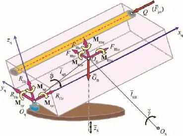
Fig.6.Tilting platform forces and moments.
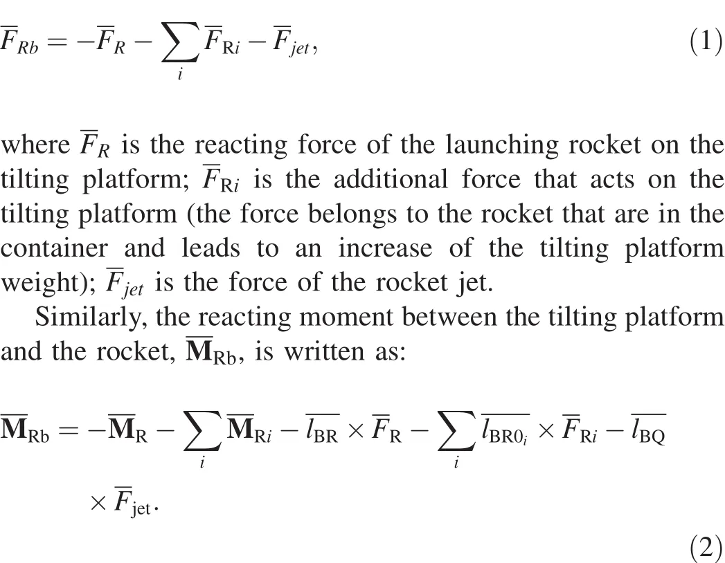
The connection forces and moments between the tilting platform and the vehicle chassis are as follows:
-RΠis the reacting force on the tilting platform,(its application point is Oη);
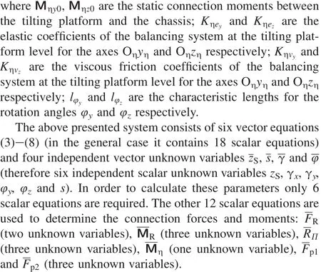
-Mηis the reacting moment on the tilting platform,with the same application point and having the components Mηx, Mηyand Mηzin the tilting platform’s system of axes(the last two components are the counter-balance moments) [4].
2.2.3.Forces and moments acting on the vehicle chassis
Furthermore,the forces and moments acting on vehicle chassis are the weight,GS,the connection forces and moments between the chassis and the tilting platform,RΠandMη(Figs. 7 and 8),as well as the connection forces between the chassis and the ground:Fa1,Fa2(at the chassis front axle),andFp1, Fp2(at the chassis rear axle)[5](Fig.9).
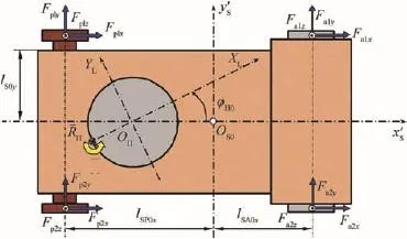
Fig.7.Vehicle chassis forces and moments.
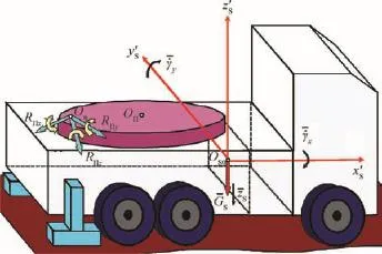
Fig.8.Vehicle chassis forces and moments.
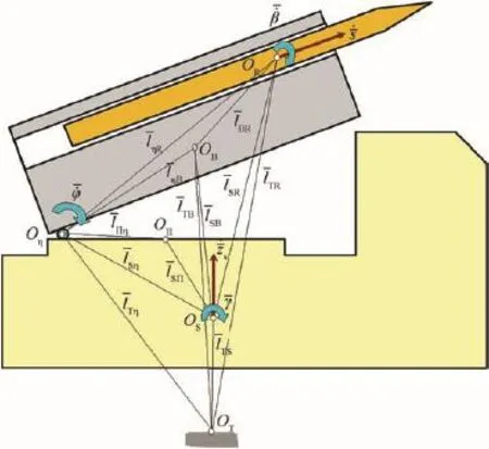
Fig.9.The calculus diagram for the rocket-launching device system.
In this paragraph we presented two categories of forces and moments according to the degree of knowledge:known forces and moments as well as unknown forces and moments[6].The known forces and moments can be determined on the basis of known parameters.They are thrust,weight of the components, vertical components of the connection forces(between the vehicle chassis and the ground)and the components of the tilting platform-chassis connection moment[10].
The unknown forces and moments are determined based on the motion equations’components:the rocket-tilting platform connection moments,the tilting platform-vehicle chassis connection moments and the horizontal components of the chassis-ground connection forces.If we know the forces and moments that act on the rocket-launching device system,we will be able to determine the general dynamic equations that describe the motion of this system during launching[4].
2.3.General dynamic equations of the rocket-launching device system
There are 6 characteristic points within the rocketlaunching device system(Fig.5):OT(the f i xed point bound up with the ground),OS(the vehicle chassis center of gravity),OΠ(the center of gravity of the revolving support),Oη(the meeting point between the axle collar of the tilting platform and the longitudinal plan of the launching device),OB(the tilting platform center of gravity)and OR(the moving rocket center of gravity)[2].
In our study,the moving rocket system of axes travels in relation to the tilting platform system of axes.At its turn,the tilting platform system of axes travels in relation to the chassis system of axes.Eventually,the chassis system of axes has the ground system of axes as a reference system(f i xed coordinate system).
Moreover,it was deemed necessary to establish the translations and rotations relative to motions of the coordinate systemsforalltherocket-launchingdevicesystem components.
On the basis of the data presented before and using the fundamental theories of the solid mechanics(impulse-momentum theorem etc.)we can determine the vector equations that describe the motion of the center of gravity and therefore the motion around it[12].
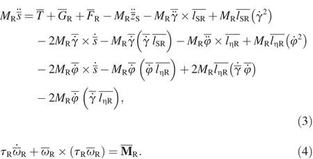
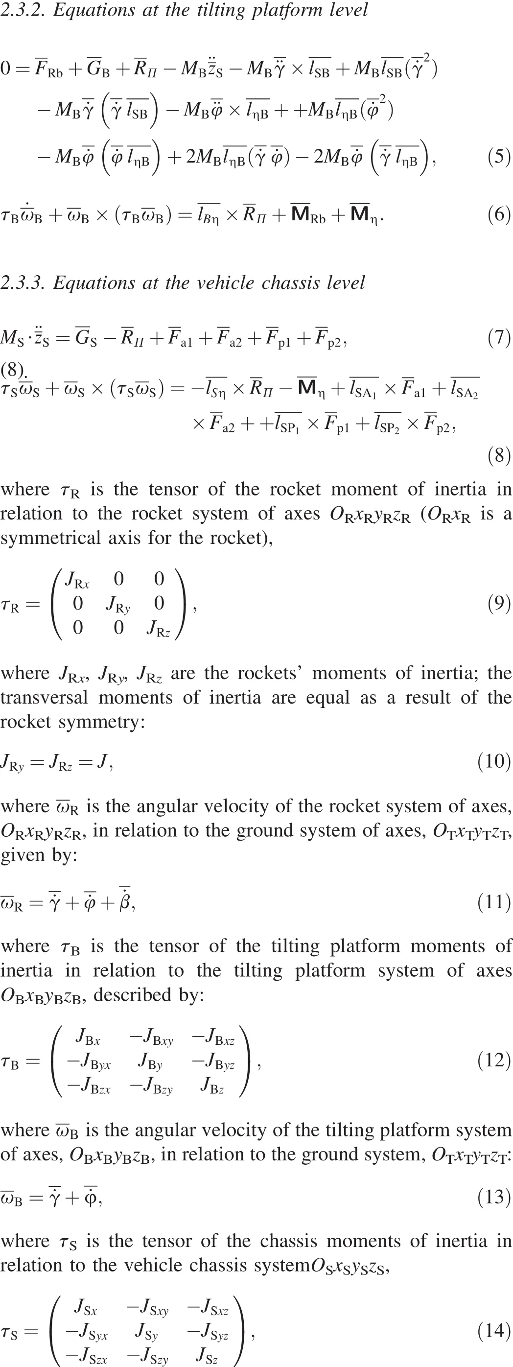
2.3.1.Equations at the moving rocket level

3.Numerical results
In the following paragraphs,we present some results obtained by numerical solution of the equation system in order to study the rocket-launching device system.Many simulations are computed in a single rocket f i ring case with the rocket in central position in the container.The evolution of the state variables that describe the rocket-launching device system(zS, γx,γy,φy,φz,φs)are presented in Figs.10-14.

Fig.10.Time history of the linear displacement zS.
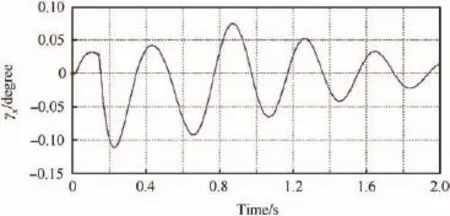
Fig.11.Time history of the angular displacement γx.
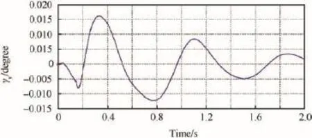
Fig.12.Time history of the angular displacement γy.
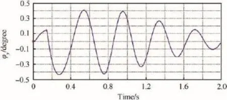
Fig.13.Time history of the angular displacement φy.
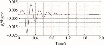
Fig.14.Time history of the angular displacement φz.
We notice that the linear displacement zSof the chassis’center of gravity has an oscillatory evolution(Fig.10)having a 0.75 s oscillating period.The oscillation amplitude has the initial value of 1.6 mm,and after the f i rst period decreases to 1 mm(62.5%from the initial amplitude).
The chassis angular displacements γxand γyhave a damped oscillatory evolution as well(Figs.11 and 12).Moreover,the oscillating period for γx(0.4 s)is smaller that for γy(0.8 s).
The γxoscillating amplitude is 0.18°while the γyoscillating amplitude is only 0.028°leading to the conclusion that the rolling oscillation is more important than the pitch oscillation.As regarding the oscillations of the tilting platform,the rotation angle φy(see Figs.13 and 14)has a larger period (0.5 s)and a larger amplitude(0.8°)than φz(0.2 s oscillating period and 0.04°oscillating amplitude).Therefore,we can conclude that at the tilting platform level the main oscillation is the pitch oscillation(φy).
4.Conclusions
As far as the evolution of the launching device oscillations during f i ring is known,one can assess the dynamic forces that develop at all levels of the launching device system component. Thatprovidesthepossibility ofanalyzingthedynamicbehavior of the whole assembly system.Whenever,assessing the oscillation parameters of a rocket-launching device system and their inf l uence upon the system stability during f i ring(such as the initial rocket f l ight condition),one implicitly assesses the f i ring accuracy.The f i ring accuracy is a fundamental requirement in the design of an accurate rocket-launching device system.
Computing the evolution of the state variables of the“rocket-launching device”system during f i ring sequences allows the evaluation of dynamic forces that are presented at all levels of the launching device system component.Hence,it is possible to analyze the dynamic behavior of the whole assembly system.These oscillations can be determined by numerically solving a theoretical model.At their turn,the results were conf i rmed by the experimental results.Eventually, the whole process leads to a signif i cant improvement of the numerical programming algorithm.
Acknowledgments
This research project would not have been possible without the support of general major professor engineer Florentin Moraru Ph.D.from Military Technical Academy.
[1]Bristeau P,Petit N.Trajectory estimation for a hybrid rocket.In:AIAA Guidance,Navigation,and Control Conference,Chicago,Illinois August 10-13,2009.
[2]Cantero D,O’Brien EJ,Gonzalez A.Modeling the vehicle in vehicleinfrastructure dynamic interaction studies.Proc Inst Mech Eng Part K-J Multi-Body Dyn 2010;224(K2):243-8.
[3]Yu CG,Ma DW,Zhang XF.Launch process simulation of a ship-borne multiple launch rocket System.World J Model Simul 2007;3(1):58-65.
[4]Dragoslav Z,Milan M,Miroslav P,Ugljeˇsa B,Duˇsan P,Zoran P. Def i ning the elasticity elimination mechanism of multiple rocket launcher vehicle.FME Trans 2011;39:171-5.
[5]Lopatka M,Muszynski T.Research of high speed articulated wheel toolcarrier steering systems.In:Proceedings of the 9th European Regional Conference of the ISTVS,Newport,United Kingdom 2003.
[6]Milliken WF,Milliken DL.Chassis design-principles and analysis. Warrendale,PA:SAE International;2002.
[7]Moraru F.A mathematical model for the rocket general movement study by use of quaternions.In:Proceedings of the 7th Symposium on Weapon Systems.Brno,Czech Republic:Military Academy;2005.
[8]Moraru F,Moraru L.On the equations of the longitudinal motion of the multicontrols aerospace vehicles.The equations in variations,associatedto the equations of motion.Revue Roumaine des Sciences Techniques 2004;49(6):55-68.
[9]Oprea R,Mihailescu M.Oscillations of the vehicles with dry friction damping.In:SISOM 2011 and Session of the Commission of Acoustics, Bucharest May 25-26,2011.
[10]Sarata S,Koyachi N,Sugawara K.Field test of autonomous loading operation by wheel loader.In:Proceedings of the 2008 IEEE/RSJ International Conference on Intelligent Robots and Systems,Nice, France 2008.
[11]S‚omoiag P.Cercetˇari privind determinarea oscilat‚iilor la lansare s‚i inf l uent‚a acestora asupra zborului rachetei.Bucharest:Military Technical Academy;2007.
[12]Voinea R.Sisteme dinamice.Bucharest:Publishing House of U P B; 1993.
5 November 2013;revised 2 December 2013;accepted 6 December 2013 Available online 20 December 2013
*Corresponding author.Tel.:+40 721288312.
E-mail address:mcrristi@gmail.com(C.E.MOLDOVEANU). Peer review under responsibility of China Ordnance Society.
Production and hosting by Elsevier
2214-9147/$-see front matter CopyrightⒸ2013,China Ordnance Society.Production and hosting by Elsevier B.V.All rights reserved.
http://dx.doi.org/10.1016/j.dt.2013.12.005
杂志排行
Defence Technology的其它文章
- Effect of Hardfacing Consumables on Ballistic Performance of Q&T Steel Joints
- Contact Force Distribution and Static Load-carrying Capacity of Large Size Double Row Four-point Contact Ball Bearing
- Study on Random Initiation Phenomenon for Sympathetic Detonation of Explosive
- Analysis of Micro-scale Flame Structure of AP/HTPB Base Bleed Propellant Combustion
- Rough Sets Probabilistic Data Association Algorithm and its Application in Multi-target Tracking
- Experimental Research on the Propagation Process of Continuous Rotating Detonation Wave