Contact Force Distribution and Static Load-carrying Capacity of Large Size Double Row Four-point Contact Ball Bearing
2013-07-25Yan-shuangWANG,Qian-qianYUAN
Contact Force Distribution and Static Load-carrying Capacity of Large Size Double Row Four-point Contact Ball Bearing
Clearance not only affects the startup torque,rotation precision and stiffness of bearing,but also affects the load distribution,load-carrying capacity and life of bearing.A computational model in which the clearance of bearing is f i rst included is presented for determining the contact force distribution and static load-carrying capacity of a double row four-point contact ball bearing which is subjected to the combined radial, axial and overturning moment loadings.The relation between the negative axial clearance and the contact force distribution is analyzed.The static load-carrying capacity curves are established,and the effects of the changes in negative axial clearance,curvature radius coeff i cient of raceway groove and initial contact angle on the static load-carrying capacity are analyzed.The results show that,with the increase in the absolute value of negative clearance,the maximum contact load decreases f i rst and then increases.The clearance values in the range of-0.2 mm-0 mm have little effect on the static load-carrying capacity of bearing.With the increase in the curvature radius coeff i cient of raceway groove and the decrease in the initial contact angle,the static load capacity of bearing decreases.
CopyrightⒸ2013,China Ordnance Society.Production and hosting by Elsevier B.V.All rights reserved.
Double row four-point contact ball bearing;Negative axial clearance;Bearing load distribution;Static load-carrying capacity
1.Introduction
The pitch bearing of a wind-power generator is basically a single row four-point contact bearing or a double row fourpoint contact bearing with either an internal gear or an external gear.It is installed in a high place ranging from 40 m to 60 m.The installation and replacement of the pitch bearing are very inconvenient,and its cost is higher[1].Therefore,the pitch bearings are requested to have a service life of twenty years and high reliability[2].Because the impact load acting on the pitch bearing is very large,the zero or negative clearance is considered to reduce fretting wear.Negative clearance not only affects the startup torque,rotation precision and stiffness of bearing,but also affects the load capacity and life of bearing.It is of great signif i cance to research the effect of negative clearance on contact load distribution and loadcarrying capacity.Because the running speed of a pitch bearing is usually small,the static load-carrying capacity, which can be described by the static load-carrying curves,is mainly considered in the pitch bearing design.
The single row four-point contact ball bearing was discussed in Refs.[3-14],and the research on the large-sized double or three row four-point contact ball bearings was discussed in Refs.[15-18].A calculation procedure for determining the load distribution in the rolling elements of a four contact-point slewing bearing with one row of balls was discussed in Ref.[3].The ball motion and sliding friction in the double arched ball bearing were analyzed in Ref.[4].The calculation method of the static load-carrying curve for turntable bearings was discussed in Refs.[8,9].A computational model for determining the static load capacity and fatigue lifetime of a large slewing bearing was described in Ref.[14].Static analysis of a double row four-point contact ball bearing was described in Refs.[16,17].All papers above described the static model without taking into account the clearance of bearing,especially the negative clearance.In this paper,taking a double row four-point contact ball bearing for example,the geometry model,static force model and the method to establish the static load-carrying curve considering the effect of negative clearance were presented.
2.Static model
2.1.Geometry model
Fig.1 shows the coordinate system of a large size double row four-point angular contact ball bearing,where x direction follows the axial direction of bearing,and r is inner radial direction.The angular position of each ball inside the bearing is φk=2π(k-1)/(Z/2),k=1,2,3…Z,where Z is the number of the balls in the double rows of bearing.
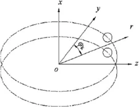
Fig.1.Coordinate system of bearing.
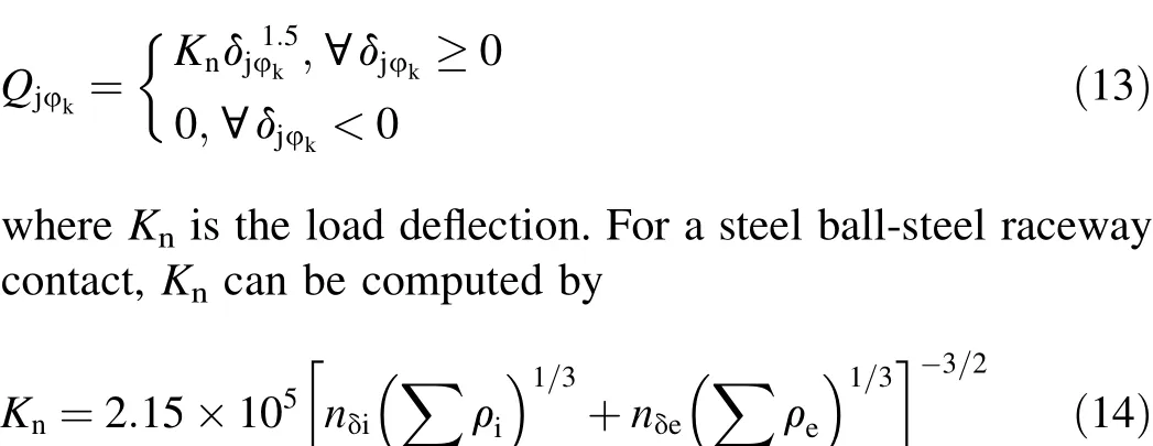
The rotating speed of the bearing is low enough to disregard the effects of the gyroscopic forces and centrifugal forces of the balls inside the bearing.So a force model of the bearing can be established according to the static force model.The procedure of establishing the model described in this paper supposes that the outer ring is f i xed in space,and the external loads,which are combined with axial load Fa,radial load Frand overturning moment load M,are applied on the inner ring, as shown in Fig.2.These combined loads cause three types of relative displacements which are relative axial displacement δa,radial displacement δrand angular displacement θ between the raceways.Fig.2 shows four types of contact pairs.Contact pairs 1 and 3 are used to carry axial loads,the corresponding other two contact pairs are expressed as contact pairs 2 and 4. In Fig.2,dmexpresses the pitch diameter of bearing;dcexpresses the distance of the centers of the two balls between the upper row and the lower row.
Under external applied loads,the raceway curvature centers reach f i nal positions,as schematically presented in Fig.3 which shows the initial and f i nal positions of the curvature centers of the upper row raceways.The centers of the leftouter,right-outer,left-inner,right-inner raceway groove curvatures in the initial position are denoted by C1el,C1er,C1iland C1irrespectively without loading.C1il'and C1ir'express the centers of the left-outer and left-inner raceway groove curvatures respectively with loading in the f i nal position.The centers of the ball with and without applied load are denoted by O1and O1',respectively.The initial contact angles between the four raceways and the balls are denoted by α0without applied load.The contact angles of contact pairs 1 and 2 are denoted by α1and α2respectively with applied load.
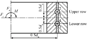
Fig.2.External applied loads on bearing.
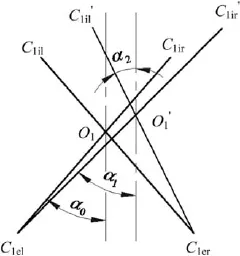
Fig.3.Initial and f i nal positions of curvature centers.
Before loading,the initial distance between the curvature centers of the inner and outer raceways can be written as[18]:

where fiis the coeff i cient of inner raceway groove curvature radius,feis the coeff i cient of outer raceway groove curvature radius,Dwis the nominal diameter of ball,and uais the axial clearance of bearing.
Before loading,the initial distance between diagonally opposed centers of curvature with zero clearance is equal to

Under external loads applied on the inner ring,the raceway curvature centers reach f i nal positions,as shown in Fig.3.The distance between diagonally opposed centers of curvature along the direction of contact pair j is def i ned as Ajφk,and it can be computed according to
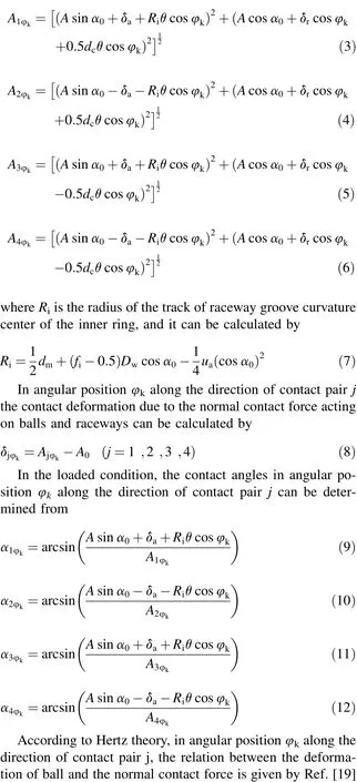
where∑ρiand∑ρeare the curvature sums for the ball-inner and ball-outer raceway contacts,respectively,and nδiand nδeare the dimensionless quantities relating to the functions of curvature differences for the ball-inner and ball-outer raceway contacts,respectively.SeeRef.[20]foradetailed presentation.
2.2.Inner ring equilibrium equations
Fig.4 shows the inner ring in the state of balance under the external applied loads and internal contact forces in angular position φk.
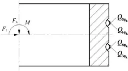
Fig.4.Forces acting on inner raceway.

Fig.5 shows the f l ow chart of calculating contact force distribution.In Fig.5,δa,δrand θ can be calculated by Eqs. (15)-(17)based on the Newton-Raphson method.The contact forces between the balls and the raceways can be obtained by substituting δa,δrand θ into Eq.(13).

Fig.5.Flow chart of calculating distribution of contact forces.
3.Determination of static load-carrying capacity curve
3.1.Allowable load of balls
The allowable stress is def i ned as the contact stress applied on a non-rotating bearing that results in a total permanent deformation of 0.000 3 of the ball diameter DWat the center of the most heavily loaded element-raceway contact.If the ring is made of steel 42CrMo,its hardness is 55HRC and its hardened depth is larger than 0.1 of the ball diameter DW,the allowable stress is suggested to be 3 850 MPa for point contact and 2 700 MPa for line contact.If the ring is made of steel 50Mn,the allowable stress is suggested to be 3 400 MPa for point contact and 2 200 MPa for line contact[10].
For point contact,the maximum contact stress at the center of the most heavily loaded ball-raceway contact is given by the following equation
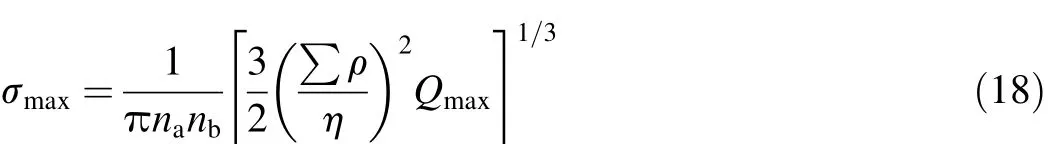
where naand nbare the dimensionless quantities relating to the functions of the curvature difference of the ball-raceway contact,seeing Ref.[18]for a detailed presentation,∑ρ is the curvature sum for the ball-raceway contact,Qmaxis the maximum ball-raceway normal contact force,η is the equivalent elastic modulus,E1and E2are the elastic moduli of the contact pair,and ν1and ν2are the Poisson’s ratio of the contact pair.
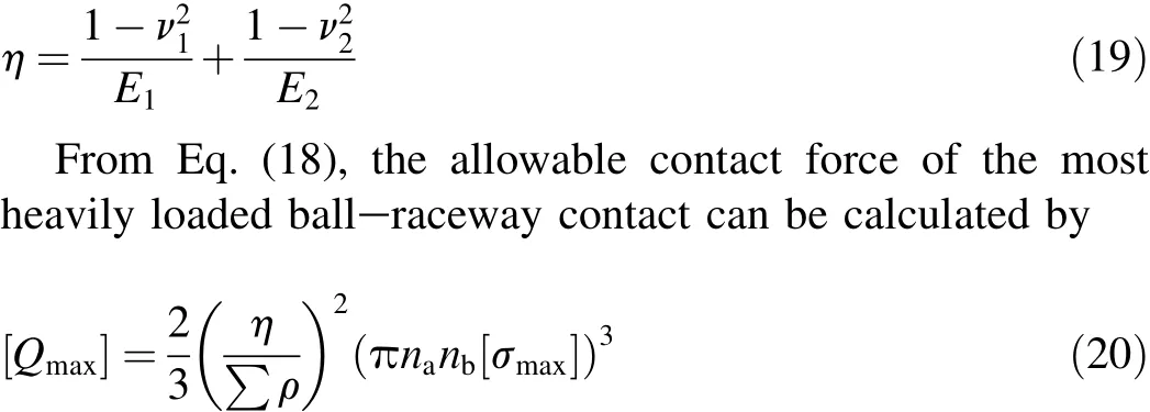
Eq.(20)shows the allowable load of the ball-raceway contact,which is determined by the material,geometry and allowable contact stress of bearing.If these parameters are known,the allowable load can be obtained.
3.2.Static load-carrying capacity curve
The static load-carrying capacity refers to a combination of the maximum allowable axial force and overturning moment. In Eqs.(15)-(17),let radial load equal be zero,and taking axial and overturning moments to continuously change the values in a certain range,the bearing contact force distribution can be computed.The maximum contact forces acting at the center of the most heavily loaded ball-raceway contact corresponding to different axial and overturning moment loads can be obtained.If these maximum contact forces approach the allowable contact force,the corresponding axial and overturning moment loads are chosen to be the points to draw the static load-capacity curve.
4.Results and discussion
4.1.Distribution of contact force
A practical example was done on a double row four-point ball bearing with the following geometry:dm=2 215 mm, DW=44.45 mm,α0=45°,dc=69 mm,ri=23.34 mm, re=23.34 mm and Z=256,where riand reare the raceway curvature radii of the inner ring and outer ring,respectively. The rings and balls of this bearing are made of steel 42CrMo. The raceways are inductively quenched,their hardness is 55-60HRC and their depth is large than 4 mm.The material properties of the raceways and the rolling elements are taken to be elastic for E=207 GPa and ν=0.3.The allowable contact stress is 3850 MPa.The external loads are taken to be Fa=250 kN,Fr=140 kN and M=1 300 kN m.The inner ring speed is taken to be ni=0.1 r/min.Because the clearance of a pitch bearing is basically zero or negative,zero and negative clearances are taken into account in this paper.
When the axial clearances are 0 mm,-0.01 mm, -0.02 mm,-0.03 mm,-0.05 mm and-0.06 mm,the distributions of contact forces along the bearing raceways are shown in Fig.6 and the numbers of balls with four-point ball-raceway contact are 4,16,36,64,225 and 256,respectively. Contact forces at each angular position have different values and directions.Taking the distribution of contact forces in zero clearance for example,as shown in Fig.6(a),when the values of angular position are 0°-99°and 260°-360°,the balls come in contact with the raceways at two points,where the direction of upper ball-raceway contact force is along the line which links the centers of curvature of contact pair 1,and the direction of lower ball-raceway contact force follows the line which links the centers of curvature of contact pair 3. When the values of angular position are 103°-256°,the balls also come in contact with the raceways at two points,but the upper ball-raceway contact force direction follows the line which links the centers of curvature of contact pair 2,and the lower ball-raceway contact force direction follows the line which links the centers of curvature of contact pair 4.When the values of angular position are 101.25°and 258.75°,the balls come in contact with the raceways at four points.When the absolute value of the negative clearance is large,for example,ua=-0.06 mm,all balls come in contact with raceways at four points(Fig.6(f)).Fig.6 shows that,with the increase in the absolute value of the negative clearance,the number of the balls with four-point ball-raceway contact increases until all the balls are in four-point ball-raceway contact.This is because the inf l uence of overturning moment load on bearing is weakened and the number of balls with four-point ball-raceway contact increases as the absolute value of the negative clearance increases.The axial and radical components of angular displacement in ball-raceway contact are different at different angular positions,which resultsindifferentcontactforces atdifferentangular positions.
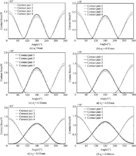
Fig.6.Distribution of contact forces on the double row four-point contact ball bearing raceways for different clearances.
Fig.7 shows the relation between the negative axial clearance and the maximum contact force on the most heavily loaded ball-raceway.It can be seen that the maximum contact force of a bearing decreases f i rst and then increases with the decrease in the absolute value of the negative clearance.When the negative clearance equals to-0.06 mm,the maximum contact force reaches a minimum value.This is mainly because the number of balls carrying loads increases with the increase in the absolute value of negative clearance,which results in the decreasing maximum contact force.When the absolute value of negative clearance increases to a certain value,all the balls carry loads.With the subsequent increase in the absolute value of negative clearance,the number of balls carrying loads doesn’t increase.But the deformation of each ball increases,which leads to the increase in the maximum contact force.The maximum contact force on the most heavily loaded ball-raceway in the upper row is larger than that in the lower row.This is mainly because the displacement of contact point at ball-raceway contact,which results from the overturning moment load,is smaller in the upper row than that in the lower row.Thus the deformation at ball-raceway contact in the upper row is larger than that in the lower row.

Fig.7.Maximum contact forces on the most heavily loaded ball-raceway contact versus negative axial clearances.
4.2.Inf l uence of geometry parameters of bearing on the static load-carrying capacity
The static load-capacity curves are shown in Fig.8 with the axial clearances of 0 mm,-0.06 mm,-0.12 mm and -0.2 mm.It can be seen from Fig.8 that the overturning moment load increases f i rst and then decreases with the increase in axial load when the negative clearances are 0,-0.06 and-0.12 mm.While the overturning moment load decreases with the increase in the axial load when the clearance is -0.2 mm.The maximum axial load which the bearing can carry decreases,while the maximum overturning moment which the bearing can carry increases with the increase in the absolute value of negative clearance.The clearances in the range from-0.2 mm to 0 mm have little inf l uence on the static load-carrying capacity of bearing.
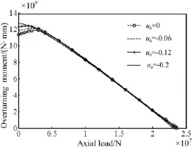
Fig.8.Static load-carry capacity curves for different negative clearances.
The coeff i cient of raceway groove curvature radius is one of the important parameters in bearing design.It affects the osculation and deformation of the ball-raceway contact,as well as the load capacity of bearing.When the coeff i cients of raceway groove curvature radius are 0.52,0.525 and 0.53,the static load-carrying capacity curves are shown in Fig.9.The overturning moment load increases f i rst and then decreases with the increase in axial load at different coeff i cients of raceway groove curvature radius,and the trends of the static load-capacity curves are almost consistent.When the coeff icient of raceway groove curvature radius increases,the maximum axial and overturning moment loads decrease and the static load-carrying capacity decreases.It is mainly because the coeff i cients of raceway groove curvature radius affect the osculation of the ball-raceway contact.As the coeff i cient of raceway groove curvature radius decreases,the osculation of the ball-raceway contact increases and the contact area increases,resulting in the increase in load-carrying capacity.
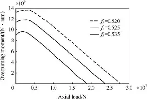
Fig.9.Static load-carrying capacity curves for different coeff i cients of raceway groove curvature radius.
Initial contact angle of bearing can also affect the loadcarrying capacity of bearing.When the initial contact angles are 45°,50°,55°and 60°,respectively,the static load-capacity curves are shown in Fig.10.It shows that the overturning moment load increases f i rst and then decreases with the increase in the axial load when the initial contact angles are 45°, 50°and 55°.And as the initial contact angle increases,the maximum axial and overturning loads as well as the load-carrying capacity of bearing increase.When the initial contact angle is 60°,the overturning moment load decreases with the increase in the axial load.The increasing amplitudes of the static load-capacity are almost same when the initial contact angle increases from 50°to 55°and 55°to 60°.When the initial contact angle increases from 45°to 50°,the increasing amplitude of the static load-capacity is nearly 3.6 times that with the increase in initial contact angle from 50°to 55°and 55°to 60°.
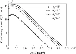
Fig.10.Static load-carrying capacity curves for different initial contact angles.
4.3.Conf i rmation of the calculated results of contact force distribution
In bearing calculation,in order to determine the maximum load,the following empirical formulae are normally used for the different load states[20].
Pure axial load:
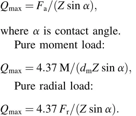
In a pure radial load state,as the formula is for two contact points,the result obtained from this formula must be divided by 2.The results for initial contact angle of 45°,clearance of 0 mm,256 balls and diameter of 2 215 mm are listed in Table 1.
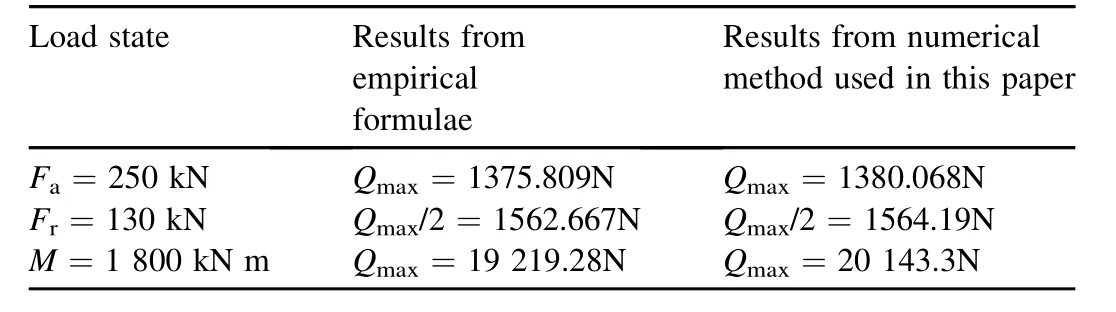
Table 1Conf i rmation of results.
Table 1 shows that the results obtained from normally used empirical formulae are very similar to those obtained from the numerical method used in this study.This indicates that the computational model and method of contact force distribution presented in this paper are valid.The empirical formulae can only be used to calculate the maximum contact force at the center of the most heavily loaded ball-raceway contact under pure load(pure axial,pure radial or pure overturning moment loads),and they do not consider the effect of geometry parameters,such as the bearing clearance,coeff i cient of raceway groove curvature radius and initial contact angle,on the contact force.The calculation method presented in this study can be used not only to calculate the maximum contact forces but also calculate the distribution of contact forces of a bearing under combined radial,axial and moment loadings,and it can also be used to analyze the effect of geometry parameters on the contact force.
5.Conclusions
A computational model of contact load distribution for a double row four-point contact ball bearing with the negative axial clearance was presented.Compared with the empirical formulae,the results show that the model is reasonable.Under the same external loads,the maximum contact force acting at the center of the most heavily loaded ball-raceway contact in the upper row is larger than that in the lower row.With the increase in the absolute value of negative clearance,the maximum contact force acting at the center of the most heavily loaded ball-raceway contact decreases f i rst and then increases.Theclearancevaluesintherangeof -0.2 mm-0 mm have little effect on the static load-carrying capability of bearing.With the increase in the coeff i cient of raceway groove curvature radius,the static load-carrying capability of bearing decreases.With the increase in the initial contact angle,the static load-carrying capability of bearing increases.
Acknowledgments
ThisresearchwassupportedbyNSFC(51105131), Excellent Youth Foundation of Henan Scientif i c Committee (124100510002)and Creative Talent Foundation in University of Henan Province(2011HASTIT016)
[1]Chen L,Du HW,Wu JK,Wang L.Summary of the bearing used in wind turbines.Bearing 2008;2:45-50[in Chinese].
[2]Zhang HW,Hu WZ,Xing ZP,Liu H.Technology and manufacture for blade bearing in mega-watt wind turbine.Bearing 2011;6:61-4[in Chinese].
[3]Amasorrain JI,Sagartzazu X,Damian J.Load distribution in a four contact-point slewing bearing.Mech Mach Theor 2003;38:479-96.
[4]Alexandre L,Daniel N.Ball motion and sliding friction in a four-contactpoint ball bearing.J Tribol 2007;10:801-8.
[5]Chen GZ,Xu SR,Yang YZ,Wang YS,Deng SE.Analysis on contact stress of large-size four-pont-contact ball bearing with negative axial internal clearance.J Mach Trans 2009;33:83-5[in Chinese].
[6]Chen L,Zhao LC,Xia XT,Qiu M.Analysis on load distribution of pitch bearing.Bearing 2010;1:1-4[in Chinese].
[7]Zupan S,Prebil I.Carrying angle and carrying capacity of a large single row ball bearing as a function of geometry parameters of the rollingcontact and the supporting structure stiffness.Mech Mach Theor 2001;36:1087-103.
[8]Su LY,Su J.Establishment of static load curve of turntable bearings. Bearing 2004;6:1-3[in Chinese].
[9]Aguirrebeitia J,Avile´s R,De Bustos IF,Abasolo M.General static load capacityinfourcontactpointslewingbearings.TribolDes 2010;66:17-23.
[10]Aguirrebeitia J,Abasolo M,Avile´s R,De Bustos IF.General static loadcarrying capacity for the design and selection of four contact point slewing bearings:f i nite element calculations and theoretical model validation.Finite Elem Anal Des 2012;55:23-30.
[11]Chaib Z,Daldie´A,Leray D.Screw behavior in large diameter slewing bearing assemblies:numerical and experimental analyses.Int J Interact Des Manuf 2007;1:21-31.
[12]Wang H,Chen Y.Calculation method for carrying capacity and rating life of slewing bearings.Bearing 2008;2:7-9[in Chinese].
[13]Liu XZ,Mao YX.Calculation on fatigue life of yaw and blade bearings. Bearing 2011;4:14-5[in Chinese].
[14]Glodeˇz S,Potoˇcnik R,Flaˇsker J.Computational model for calculation of static capacity and lifetime of large slewing bearing’s raceway.Mech Mach Theor 2011;8:1-15.
[15]Ludwik K.Modelling of rollers in calculation of slewing bearing with the use of f i nite elements.Mech Mach Theor 2006;41:1359-76.
[16]Gao XH,Huang XT,Wang H,Chen J.Distribution of loads in a double row four-point-contact ball slewing bearing.J Nanjing Univ Technol(Nat Sci Ed)2011;33:80-3[in Chinese].
[17]Wang SM,Liu JW,Xu MH.Mechanical analysis on pitch bearing of wind turbines.Chin J Construct Mach 2011;9:73-6[in Chinese].
[18]Wang YS,Yuan QQ.Inf l uence of negative clearance on load distributions of large-size double row four-point-contact ball bearings.J Mech Eng 2012;48(21):110-5[in chinese].
[19]Harris T.Rolling bearing analysis.New York:John Wiley&Sons Inc; 2006.
[20]Deng SE,JIA QY,Wang YS.Rolling bearing design theory.China Standard Press;2009[in Chinese].
Yan-shuang WANG*,Qian-qian YUAN
Henan University of Science and Technology,Luoyang 471003,China
5 November 2013;revised 3 December 2013;accepted 3 December 2013 Available online 17 December 2013
*Corresponding author.Tel.:+86 13721663138.
E-mail address:yswang@haust.edu.cn(Y.-S.WANG). Peer review under responsibility of China Ordnance Society
Production and hosting by Elsevier
2214-9147/$-see front matter CopyrightⒸ2013,China Ordnance Society.Production and hosting by Elsevier B.V.All rights reserved.
http://dx.doi.org/10.1016/j.dt.2013.12.003
杂志排行
Defence Technology的其它文章
- Effect of Hardfacing Consumables on Ballistic Performance of Q&T Steel Joints
- Numerical Research on The Stability of Launching Devices During Firing
- Study on Random Initiation Phenomenon for Sympathetic Detonation of Explosive
- Analysis of Micro-scale Flame Structure of AP/HTPB Base Bleed Propellant Combustion
- Rough Sets Probabilistic Data Association Algorithm and its Application in Multi-target Tracking
- Experimental Research on the Propagation Process of Continuous Rotating Detonation Wave