Temperature sensor based on polymer thin film optical waveguide
2013-01-08WangLongdeZhangTongZhangXiaoyangLiRuozhouWangLuning
Wang Longde Zhang Tong Zhang Xiaoyang Li Ruozhou Wang Luning
(1School of Electronic Science and Engineering, Southeast University, Nanjing 210096, China)(2Department of Chemistry and Chemical Engineering, Huainan Normal University, Huainan 232001, China)(3Key Laboratory of Micro-Inertial Instrument and Advanced Navigation Technology of Ministry of Education, Nanjing 210096, China)(4Suzhou Key Laboratory of Metal Nano-Optoelectronic Technology, Suzhou Research Institute of Southeast University, Suzhou 215123, China)
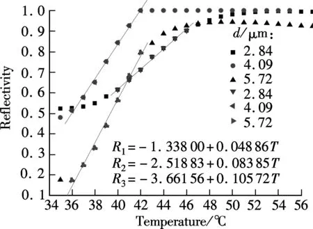
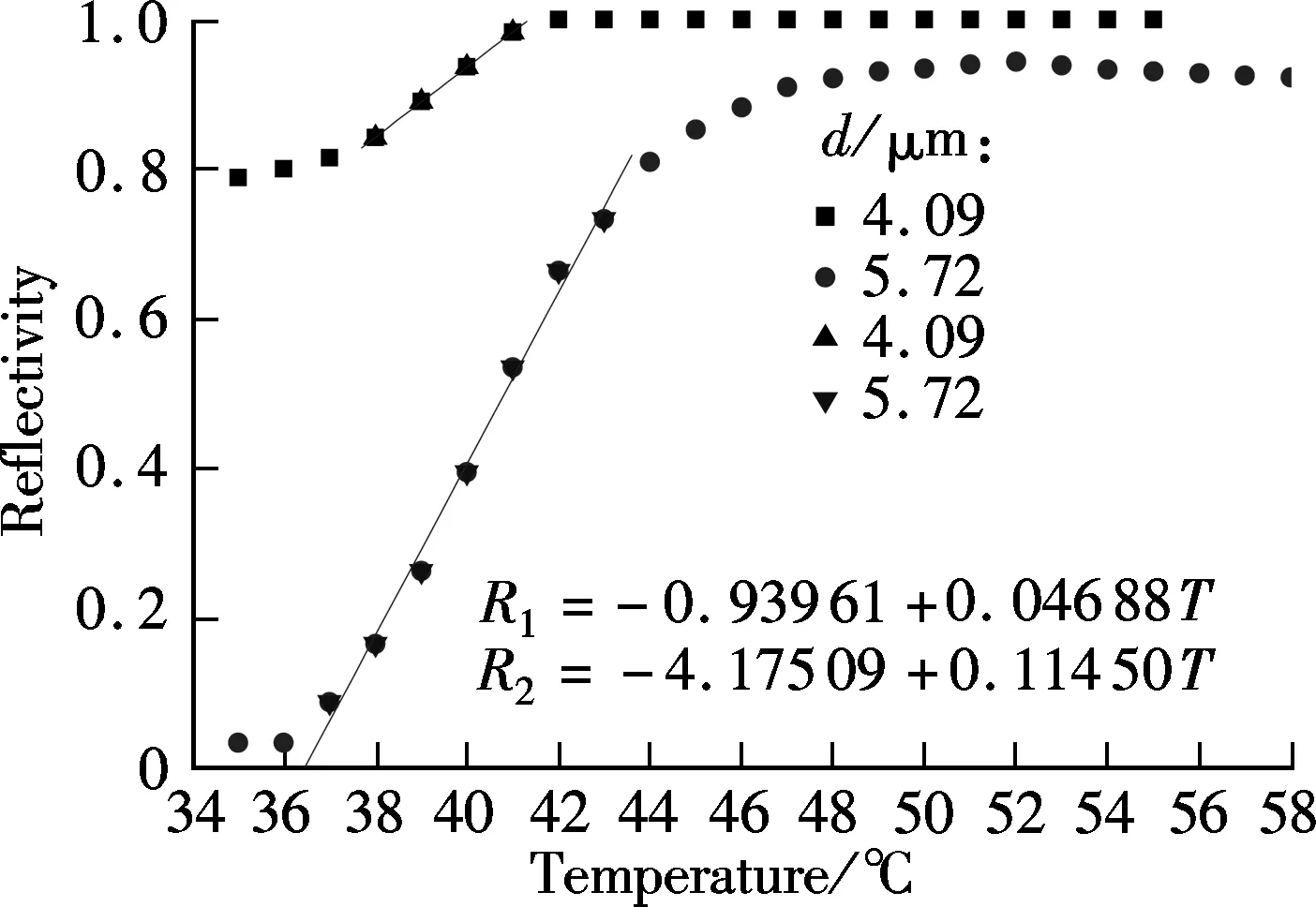
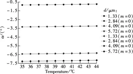
Optical sensors have a potential application for temperature measurement in areas such as scientific experiments, chemistry, biochemistry, and industrial process control. Temperature sensing based on optical techniques is promising and remains an area of continuing and intensive research interest in recent years[1-3]. Fiber-optic temperature sensors constitute a major category of the optical temperature sensors[4-7]. Benefiting from the development of planar optical integration technology, optical sensors have been developed from using optical fiber as platforms to using easy-integrated planar waveguides. Currently, temperature sensors research based on optical planar waveguides is focused on surface plasmon resonance (SPR) sensors or other novel sensors[8-12]. However, the studies in optical planar waveguide temperature sensors using prism coupling waveguides are relatively fewer. Especially, to the best of our knowledge, very few people use the high-order guided modes to measure temperature.
Polymers, owing to their high thermo-optic coefficients, have been considered for use in optical temperature sensors[13-15]. In this paper we propose an optical sensor to measure temperature using the guided mode of a planar polymer optical waveguide. The principle of the sensor is based on the attenuated total reflection and the thermo-optic effects of polymer. Theoretical analysis and the experimental setup of the method are introduced and discussed in detail. We demonstrate the characteristics of the TE0mode and the higher-order TE modes in optical waveguide mode transmission using temperature sensing. The experiments demonstrate that the measurement range and ease of implementation are particular advantages of this technique.
1 Theoretical Analysis and Simulation
The proposed configuration of the sensor is shown in Fig.1(a). The sensor consists of a high-index prism, an upper cladding layer, a SU8-2005 polymer thin film and a silica substrate. Under the substrate there is a heater plate. A transverse electric (TE) wave polarized laser beam is incident onto these films from the prism side.
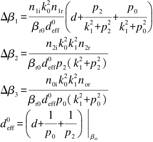
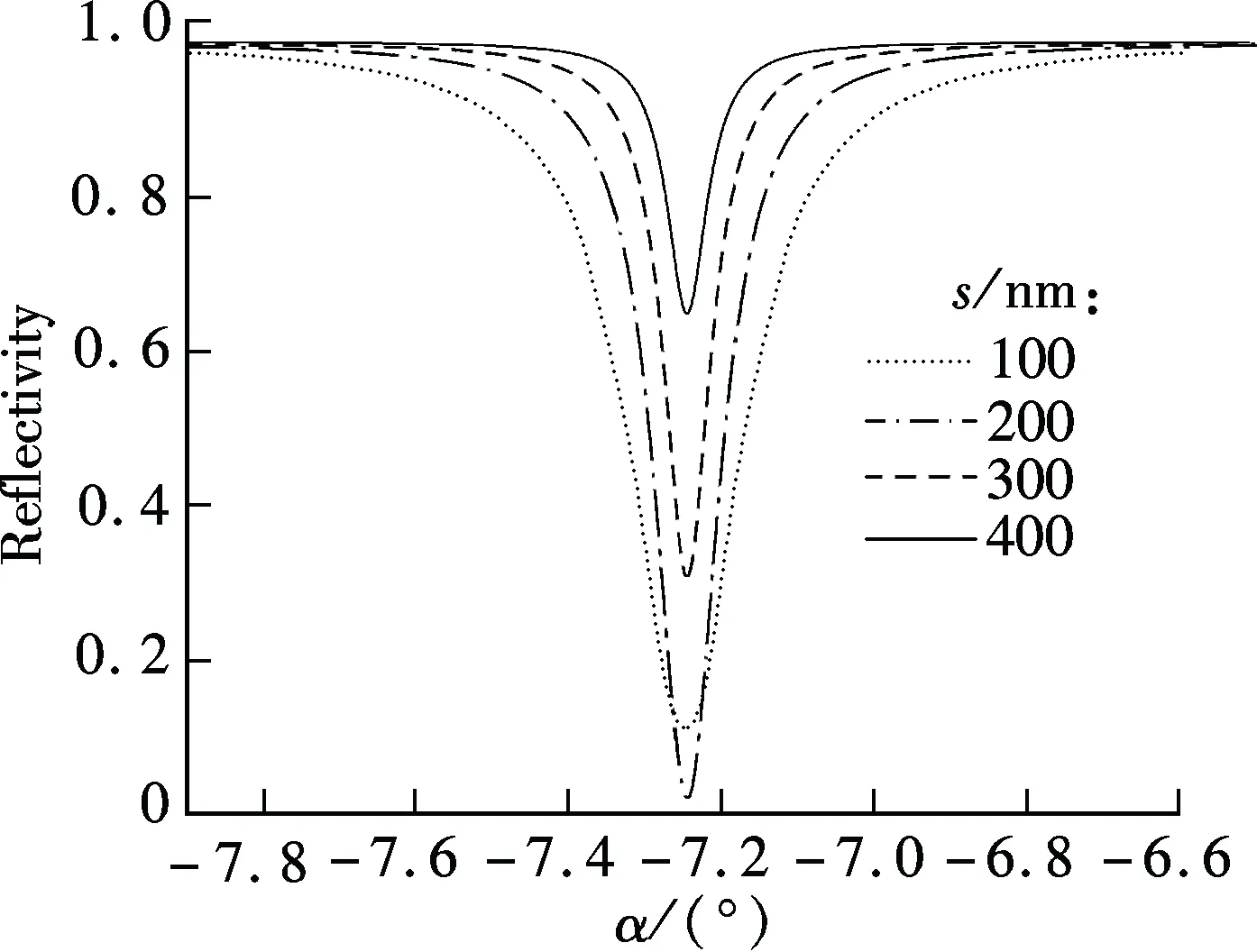
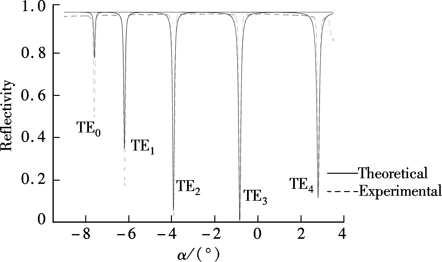
When a TE-polarized light beam is incident on the base of the prism with an interior angleθgreater than the critical angle between the prism medium and the air layer, the incident light beam reflects at the interface of the prism and the air layer, and creates an evanescent field inside the air. At a synchronous incident interior angleθ, the evanescent field is phase-matched to the guided wave in the polymer layer; that is to say, the interior angleθof the incident light at wavelengthλsatisfies the optical waveguide mode transmission condition, and the energy of incident light can be effectively coupled into the three-layer (air-polymer-fused silica) thin-film waveguide to excite guided waves, and the corresponding ATR resonance dips are shown on the reflection spectrum[16]. Disregarding the prism face and the refraction of the input beam, the proposed sensor can be regarded as a four-layer system as shown in Fig.1(b). For waveguide modes in this system to be excited, the following conditions must be satisfied:n2 Fig.1 Schematic diagram. (a) Proposed waveguide temperature sensor; (b) Representation of four-layer system R=rr*=|ei2φ32|2· (1) where β0is the eigen propagation constant of the ideal three-layer waveguide in the absence of the prism;β=k0n3sinθis the propagation constant;k0is the wave vector in vacuum. When we consider the three-layer waveguide losses, we deduce the formula ofβ0, Δβ1, Δβ2and Δβ3as follows: β0=βr0+i(Δβ1+Δβ2+Δβ3) where Δβ1, Δβ2, Δβ3are considered as the change ofβ0with considering imaginary parts ofn1,n2,n0;βr0is the eigen propagation constant of the ideal three-layer waveguide whenn1,n2andn0are real numbers. The imaginary parts ofβ0and Δβare the intrinsic and radiative losses, respectively. The former represents the eigen loss in the ideal three-layer polymer waveguide, and the latter represents the leakage loss of the guided modes back into the prism. From Eq.(1), we can conclude that if Im(β0)=Im(Δβ), thenR=0. That is to say, when the intrinsic loss is equal to the radiative loss, the minimal reflectionRminof the ATR guided wave resonance dip is zero[17]. Heating the polymer can change the propagation constant of the guided wave mode through the varying refractive index of the polymer due to the thermo-optic effect; thus, the synchronous incident exterior angleαand the minimal reflectionRminof the ATR guided wave resonance dip are varied. The effective refractive index of each modeNmis given by (2) From Eq.(2), we can obtain that (3) The mode indices for integral values ofNare given by[18] (4) Substituting Eq.(4) into Eq.(3), we obtain (5) Through measuring the thermo-optic coefficient dn/dTof the SU8 polymer by the SPA-4000 prism coupler containing a miniature heating device with an accuracy of ±0.1℃ under the samples, we can obtain the relationships about the refractive index of polymer and temperature:n1=1.573 07-1.34×10⁻⁴T,d=1.33 μm;n1=1.572 39-1.34×10⁻⁴T,d=2.84 μm;n1=1.573 45-1.38×10⁻⁴T,d=4.09 μm;n1=1.572 57-1.34×10⁻⁴T,d=5.72 μm. Substitutingn1into Eq.(5), we can obtain the function of the light incident exterior angleαand the measurement temperatureT. The performance of a temperature sensor is associated with both the minimal reflection and the full width at half maximum (FWHM) of ATR resonance dip. The deep and narrow resonance dip allows a greater degree of modulation for a given temperature. The theoretical simulation results of Fig.2 are the working base of the sensor under the conditions ofd=4.09 μm,n1=1.568 6+0.000 3i,n2=1.000+0.000 01i,n0=1.444 2+0.000 01i,n3=1.934 9,λ=1 550 nm,T=35 ℃. The guided modes are determined by changing the thickness of the coupling layer. It is known that the minimal reflection and FWHM of ATR resonance dip increase with the increase in the optical losses of the coupling layer and the guiding layer[17, 19].Once the materials of the coupling layer and the polymer are selected, the match condition illustrated by Eq.(1) can be reached by adjusting the thickness of the coupling layer and the guiding layer to make the intrinsic loss equal the radiative loss so that the minimal reflection of the resonance dip approaches zero. Fig.2 Theoretical simulation resonance reflectivity dips TE modes for several thicknesses of the coupling layer. (a) s=150 nm; (b) s=250 nm; (c) s=350 nm;(d) s=450 nm Because the imaginary part ofβ0changes with the thickness of the guiding layer, the minimal reflection of the resonance dip changes not only with the thickness of the coupling layer but also with the guiding layer. The properties of ATR resonance dip using the gas coupling layer can be optimized by choosing proper thicknesses of both the coupling layer and the guiding layer. Figs.3 and 4 are the theoretical plots from Eq.(1) of the minimal reflection of the resonance dip TE0vs. the thickness of the coupling layer and the guiding layer respectively. It can be seen that the thickness of the coupling layer and the guiding layer both contribute to the minimal reflection. Fig.3 also shows that the FWHM of ATR resonance dip is relevant to the thickness of the coupling layer. The dips in the reflection intensity are due to the coupling of energy into the waveguide. The minimum position corresponds to the synchronous angle of the excitation mode and determines the working angle. The minimum value gives the maximum energy coupling efficiency and determines the sensitivity of the polymer thin film temperature sensor. The width of the dip is a function of the loss and determines the sensitivity of the temperature sensor. The modes are broadened due to attenuation by leakage both into the silica substrate and the prism. When the thickness of the coupling layers=400 nm, the width of the resonance dip is narrow. From Fig.5, we know that the reflectivity is a function of the angle of incidence and the thickness of the guiding layer. The sensor’s working incident exterior angle can be chosen to be TE0in lower thicknesses or higher-order TE modes in higher thicknesses of the waveguide. Fig.3 Theoretical simulation resonance reflectivity dips TE0 for several thicknesses of the coupling layer (d=4.0 μm,n1=1.576 9+0.000 3i,n2=1.000+0.000 01i, n0=1.444 2+0.000 01i, n3=1.934 9, λ=1 550 nm, T=30℃) Fig.4 Theoretical simulation resonance reflectivity dips TE0 for several thicknesses of the guiding layer (s=400 nm, n1=1.576 9+0.000 3i, n2=1.000+0.000 01i, n0=1.444 2+0.000 01i, n3=1.934 9, λ=1 550 nm) Fig.5 Theoretical and experimental ATR spectrums of the thickness of 5.72 μm guiding layer waveguide In our experiment the refractive index of the prism isn3=1.965 4 at the wavelength of 1 550 nm. Selecting the SU8-2005 polymer as the optical waveguide material is due to the fact that the SU8 has a higher thermo-optic coefficient and a lower propagation loss and it also has the ability of forming stable films. The polymer thin-films of 1.33, 2.84, 4.09 and 5.72 μm are spin-coated onto the polished fused Silica substrate, pre-baked at 95 ℃ for 120 s, then cured by UV-exposure for 2 s and finally baked at 95 ℃ for 12 h in an oven to complete removal of the solvent from the film. The SU8 polymer solution is then filtered through a 0.22 μm filter before it is applied. The ATR spectrums of the multilayer waveguide system are generated as shown in Fig.5. Several resonance dips that correspond different guided modes are shown in the spectrum in choosing the sensor’s working interior angle to be near the TE3resonance dip. The experimental result of light reflectivity for TE0vs. the temperature in different thicknesses of the guiding layer for the proposed waveguide sensor is shown in Fig.6. From Fig.6 we know that the reflectivity and temperature is in accord with a good linear relationship at 36 to 43 ℃. The results show that the slope which stands for the sensitivity of the polymer thin film temperature sensor is associated with the waveguide film thickness and the guided modes. Fig.7 shows the theoretical results of the light reflectivity vs. the temperature in different thicknesses of the guiding layer for the waveguide temperature sensor. From Fig.7 it can be obtained that the theoretical result is consistent with the experimental result in Fig.6. The slope is relevant to TE modes but not relevant to the thickness of the guiding layer when the imaginary part ofn1does not change with the thickness of the guiding layer. Fig.6 Experimental results of light reflectivity vs. measurement temperature in different thicknesses of guiding layer for proposed waveguide sensor (m=0) Fig.7 Theoretical results of light reflectivity vs. measurement temperature in different thicknesses of the guiding layer for proposed waveguide sensor (n1i=0.000 3i,n2=1.000+0.0000 1i,n0=1.444 2+0.000 01i,n3=1.934 9,λ=1 550 nm) Figs.8 and 9 show the light reflectivity of TE1and TE2vs. the temperature in different thicknesses of the guiding layer for the proposed waveguide sensor. From Figs.6, 8 and 9, we can obtain that for the same guiding layer thickness, the slope decrease with the increase in the guided modes when reflectivity is zero for TE0. For instance, if the thickness of the guiding layer is 4.09 μm, the slope values of TE0, TE1, TE2are 0.146 38, 0.083 85, 0.046 88, respectively. Nevertheless, for a film thickness of 5 720 nm, the slope values of TE0, TE1,TE2and TE3are 0.072 29, 0.105 72, 0.114 5, 0.121 67, respectively. The slope value is the highest in TE3where the reflectivity is zero in Fig.5. Therefore, to improve the sensitivity, the sensor’s working incident light exterior angleαcan be chosen to be in a certain TE mode in which the reflectivity is zero. Fig.10 shows the theoretical and experimental light incident exterior angleαof TE vs. the temperature of the guiding layer for the waveguide sensor. The experimental results are in agreement with the results derived from Eq.(5) and experimental datan1. Fig.8 Light reflectivity of TE1 vs. measurement temperature in different thicknesses of the guiding layer for proposed waveguide sensor (m=1) Fig.9 Light reflectivity of TE2 vs. measurement temperature in different thicknesses of the guiding layer for proposed waveguide sensor (m=2) Fig.10 Theoretical and experimental light incident exterior angle of TE vs. measurement temperature of the guiding layer for proposed waveguide sensor We demonstrate a polymer thin film waveguide temperature sensor based on guided wave resonance with the ATR structure. The property of the polymer thin film optical waveguide temperature sensor is heavily dependent on the planar optical guiding modes, the loss of the polymer, the thickness of the guiding layer and the cladding layer. The relationships among temperature, refractive index, reflectivity, TE modes and the incident light exterior angle of the prism are systematically investigated. The slope about reflectivity and temperature which stands for the sensitivity of the polymer thin film temperature sensor is associated with the waveguide film thickness and the guided modes. The sensor’s working incident light exterior angleαshould be chosen under a certain TE mode with the reflectivity to be zero, and, in this case, the temperature sensor has the highest sensitivity. This temperature sensor is characterized by high sensitivity and simple structure and it is easily fabricated. [1]Andersen T B, Han Z H, Bozhevolnyi S I. Compact on-chip temperature sensors based on dielectric-loaded plasmonic waveguide-ring resonators[J].Sensors, 2011,11(2): 1992-2000. [2]Childs P R N, Greenwood J R, Long C A. Review of temperature measurement[J].RevSciInstrum,2000,71(8): 2959-2978. [3]Chen J H, Huang X G, He W X, et al. A parallel-multipoint fiber-optic temperature sensor based on Fresnel reflection[J].OpticsandLaserTechnology, 2011,43(8): 1424-1427. [4]Lee B. Review of the present status of optical fiber sensors[J].OptFiberTechnol, 2003,9(2): 57-79. [5]Sharma A K, Jha R, Gupta B D. Fiber-optic sensors based on surface plasmon resonance: a comprehensive review[J].IEEESensJ, 2007,7(8): 1118-1129. [6]Remouche M, Georges F, Meyrueis P. Flexible optical waveguide bent loss attenuation effects analysis and modeling application to an intrinsic optical fiber temperature sensor[J].OpticsandPhotonicsJournal, 2012,2(1): 1-7. [7]Zeng X, Wu Y, Hou C L, et al. A temperature sensor based on optical microfiber knot resonator[J].OpticsCommunications,2009,282(18): 3817-3819. [8]Lee S M, Ahn K C, Sirkis J S. Planar optical waveguide temperature sensor based on etched bragg gratings considering nonlinear thermo-optic effect[J].KSMEInternationalJournal, 2001,15(3): 309-319. [9]Lee D R, Cho K M, Jang S W, et al. Side-polished fiber optic temperature sensor using a prism and fiber-to-planar waveguide coupler[J].MicrowaveandOpticalTechnologyLetters, 2005,46(6):523-525. [10]Dumais P, Callender C L, Noad J P, et al. Temperature sensors and refractometers using liquid-core waveguide structures monolithically integrated in silica-on-silicon[C]//ProceedingsofSPIEonOpticalSensorsandDetectors. Montréal, Canada, 2008,7099: 1-11. [11]Remouche M, Mokdad R, Chakari A, et al. Intrinsic integrated optical temperature sensor based on waveguide bend loss[J].OpticsandLaserTechnology, 2007,39(7):1454-1460. [12]Seo J K, Kim K J, Oh M C. Integrated-optic temperature sensors based on guided-mode radiation in polymer waveguide[J].OpticsCommunications, 2010,283(7): 1307-1310. [13]Rindorf L, Bang O. Highly sensitive refractometer with a photonic-crystal-fiber long-period grating[J].OpticsLetters, 2008,33(6): 563-565. [14]Jung W G, Kim S W, Kim K T, et al. High-sensitivity temperature sensor using a side-polished single-mode fiber covered with the polymer planar waveguide[J].IEEEPhotonicsTechnologyLetters, 2001,13(11): 1209-1211. [15]Chen J G, Zhang T, Zhu J S, et al. Low-loss planar optical waveguides fabricated from polycarbonate[J].PolymerEngineeringandScience, 2009,49(10): 2015-2019. [16]Tien P K, Ulrich R. Theory of prism-film coupler and thin-film light guides[J].JOptSocAm, 1970,60(10):1325-1337. [17]Deng X X, Cao Z Q, Shen Q S, et al. An improved configuration of reflective-type electro-optic modulator with high light-induced damage threshold[J].OpticsCommunications, 2004,242(4): 623-630. [18]Lee H J, Henry C H, Orlowsky K J, et al. Refractive-index dispersion of phosphosilicate glass, thermal oxide, and silicon nitride films on silicon[J].AppliedOptics, 1988,27(19): 4104-4109. [19]Koynov K, Goutev N, Fitrilawati F, et al. Nonlinear prism coupling of waveguides of the conjugated polymer MEH-PPV and their figures of merit for all-optical switching[J].JOptSocAmB, 2002,19(4):895-901.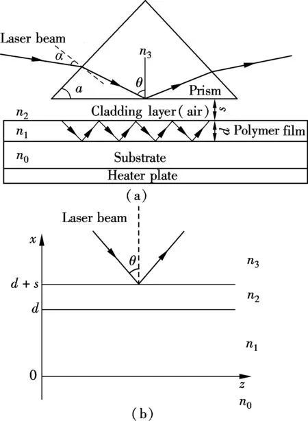




2 Experimental Results and Discussion


3 Conclusion
杂志排行
Journal of Southeast University(English Edition)的其它文章
- Price and retailer’s service level decision in a supply chain under consumer returns
- Investigation on transformation process of trip mode choicefor planned special events
- Fuzzy traffic signal control with DNA evolutionary algorithm
- Alcohol dehydrogenase coexisted solid-state electrochemiluminescence biosensor for detection of p53 gene
- Adjacent vertex-distinguishing total colorings of ∨Kt
- Aggregating metasearch engine results based on maximal entropy OWA operator
