环氧/氟碳复合涂层失效过程的电化学阻抗谱研究
2012-11-30唐聿明熊金平
庞 然 左 禹 唐聿明 熊金平
(北京化工大学材料科学与工程学院,碳纤维与功能高分子教育部重点实验室,北京100029)
环氧/氟碳复合涂层失效过程的电化学阻抗谱研究
庞 然 左 禹*唐聿明 熊金平
(北京化工大学材料科学与工程学院,碳纤维与功能高分子教育部重点实验室,北京100029)
用电化学阻抗技术研究了环氧富锌底漆、环氧云铁中间漆和氟碳面漆构成的多层复合涂层在四种不同腐蚀环境中的失效过程.涂层在四种环境中的失效速率按下列顺序降低:3.5%NaCl浸泡+紫外照射,45°C湿热环境,35°C盐雾试验,3.5%NaCl浸泡.尽管涂层在四种不同环境中失效速率差别很大,但不同环境中阻抗中频区的相角,尤其是10 Hz频率的相角,与涂层的低频阻抗值变化趋势非常接近.由于中频区的相角可以快速测量,因此可以作为在工程现场定性评价涂层保护性能的参数.
氟碳涂层;电化学阻抗谱;性能;失效;快速评价;相角
1 Introduction
Coatings are widely used in various applications.To maintain good coating performance,it is very important to detect the coating performance in corrosion environments.Electrochemical impedance spectroscopy(EIS)is one of the major technologies to evaluate the performance and failure process of coating systems.1-5By analyzing the impedance spectra,some parameters may be obtained such as coating resistance,coating capacitance,electrochemical reaction resistance,and double layer capacitance,which provide evaluation on the coating systems.6-11The coating resistance or the impedance at low frequency is usually used to evaluate the coating performance. Generally,the coatings with resistance over 108Ω·cm2provide good corrosion protection,while those with resistance under 106Ω·cm2provide poor corrosion protection.12,13Macedo et al.14recently studied the performance of epoxy,alkyd,and poly-urethane paints by EIS,pointing out that although EIS(both global and local)is an excellent tool to monitor the behavior of organic coatings,a deeper understanding of the electrolyte/ paint film interactions is absolutely essential to correctly analyze the impedance data.In addition,because of the relatively long testing time and the complicated spectrum analysis,EIS methods are mainly applied in laboratory studies.Some authors studied fast evaluation methods for coating performance by EIS,trying to find the parameters which both reflect the coating performance and can be obtained quickly,in order to avoid the complicated spectrum analysis.Akbarinezhad et al.15reported that the decreasing percentage(DP)of the areas under Bode plots were useful parameters for evaluating coating degradation during immersion.Haruyama et al.16proposed a breakpoint frequency method,suggesting that the frequency at which the phase angle first fell to 45°,fb,was related to the coating resistance.Therefore,the disbonded area of coating to the metal may be estimated by measuring the fbvalue.Mansfeld and Tsai17analyzed corrosion behavior of steels with different coating systems by the minimum phase angle Φminand its frequency fmin.The results showed that the coating performance can be quickly evaluated by Φminand fmin.Mahdavian and Attar.18pointed out the direct relation between phase angle and coating resistance via the contrast experiments of zinc chromate and zinc phosphate coatings,and analyzed the corrosion tendency of the coating with the phase angle at 10 kHz.Mehta and Bogere19also pointed out that phase angle in the high frequency range(~104Hz)reflected chemical/water diffusion within the dielectric and demonstrate decreased capacitive behavior of the polymer film.However,the phase angle at 10 kHz usually varies in the later stage of the coating performance.In the early and middle stages,the phase angle at 10 kHz remains high value close to 90°.Our previous work indicated that the variation tendencies of the phase angles in middle frequency range were very similar to the variation tendency of the coating resistance.20For epoxy/chlorinated rubber and inorganic/fluorocarbon coating systems,the variation of phase angle at 10 Hz may reflect the variation of the coating performance well. Therefore,the phase angle at a middle frequency such as 10 Hz may be related to coating resistance and the coating performance in the early and middle stages.However,more studies in different coating/environment systems are needed to confirm this phenomenon.
Fluorocarbon coatings are widely used in various applications.The fluorocarbon coatings prepared with fluororesin as a base material show strong weatherability and good corrosion resistance because of the existence of high energy C-F bonds in fluororesin molecules.In this work the electrochemical behaviors of a multi-layer coating system(zinc-rich epoxy primer,epoxy middle coating with ferric oxide flakes,and fluorocarbon topcoat)in four different corrosive environments were studied with EIS,and since the low frequency impedance is a frequently used parameter to evaluate the coating performance, the relationship between the phase angle and the coating impedance was discussed.
2 Experimental
2.1 Material and sample preparation
The metal matrix used was Q235(corresponding to ASTM A-36)carbon steel panels,with a size of 40 mm×40 mm×0.8 mm.The sample surface was finished manually with 120# abrasive papers,and cleaned with ethanol and acetone in turn. The coatings applied are listed below:
Type 801 zinc-rich epoxy coating:4.15% epoxy resin, 1.85%methyl isobutyl ketone,4.0%dimethylbenzene,1.0%nbutanol,86.75%zinc powers(8-12 μm)and 2.25%polyamide resin(produced by Beijing Hang Cai Bai Mu New Material Technology Co.,Ltd.,China).
Type 701-2 epoxy middle coating with mica iron:43.1%epoxy resin,6.68%chlorinated paraffin,7.84%iron oxide red, 7.84%zinc oxide,3.92%mica power and 3.92%barium sulfate.(produced by Shijiazhuang Goldenfish Coatings Co.,China).
Type ZB-01-3 fluorocarbon topcoat:40%Lumiflon resin, 30%ethyl isobutyl ketone,10%dimethylbenzene,9%titanium white,4%isocyanate dimmer(produced by Dalian Zebon Coatings Co.,China).
A triple-layer coating system,with the zinc-rich epoxy coating as the primer,the epoxy coating with ferric oxide flakes as middle layer,and the fluorocarbon coating as the topcoat,was coated onto the steel panels by manual brushing.The time interval between each coating was 24 h.Table 1 shows the thickness of each layer and the total thickness of the coatings tested. As the coating thickness was difficult to control by manual brushing,for each condition several coating samples were prepared,and the samples with the coating thickness most close to the values in Table 1 were selected for testing.The coating thickness was measured with a TT220 thickness meter(Time Instruments Co.Ltd.,China).For each condition 15 measurements were carried out and the average value was taken.
2.2 Corrosion tests
Corrosion tests were carried out in four different environments:(1)T1:exposed in salt spray environment at a constant temperature of 35°C.(2)T2:immersed in 3.5%NaCl solution at room temperature(~20°C).(3)T3:immersed in 3.5%NaCl solution,about 1-2 cm depth to the solution surface,and at the same time exposed to an ultraviolet lamp(produced by Youwei South China Co.Limited,with the power of 1 kW and the peak value of the spectrum at 365 nm)at a distance of 40 cm.Dur-ing testing the solution temperature increased to about 58°C due to the heating effect of UV lamp.(4)T4:exposed in air, 0.5 cm above water surface,with the constant temperature of 45°C.

Table 1 Thickness of the coatings for different environments
2.3 EIS measurements
The above coating samples were removed from the experimental environments for different exposure time,and EIS measurements were carried out in 3.5%NaCl solution at room temperature with a PARSTAT 2273 advanced electrochemical system(Princeton Allpled Research,USA).Impedance spectra were obtained at open circuit potential with a 10 mV sine perturbation.The measuring frequency range was 105-10-2Hz. The exposed area of the working electrode was 13 cm2.The reference electrode was a saturated calomel electrode and a Pt flat was used as counter electrode.ZSimpWin software was used to analyze the electrochemical impedance spectra in order to obtain the electrochemical parameters of the coatings.
2.4 FTIR spectroscopy
The coating samples after exposure in different environments were analyzed with Fourier transform infrared(FTIR) spectroscopy(Thermo Nexus 8700,USA).The coating powders removed from the substrates were pressed into thin pieces for analysis.
3 Results and discussion
3.1 EIS results of the coating samples in salt spray environment(T1)
For each condition,three parallel tests were carried out. Fig.1 shows the illustrations where Fig.1a shows Nyquist plots for three parallel samples immersed in 3.5%NaCl solution for 9889 h,and Fig.1b shows the impedance values of the coating samples with immersion time.The results show that the reproducibility of the measurements is quite good.In the following analysis,for each condition the intermediate curve among three parallel tests is taken.Fig.2a shows the Bode plots of the coating samples at different exposure time in salt spray environment.During the early stage of the test,the coating impedance value was close to 1010Ω·cm2in the low frequency domain of the Bode plot,indicating good performance of the coating system.As testing time prolonged,the coating impedance value gradually decreased and a flat occurred on the impedance curve in low frequency domain.For different testing time, the phase angles in higher frequency range remained high values.However,in lower frequency range the phase angle varied obviously with exposure time.Therefore,it is clear that there is close relationship between failure process of the coating system and the changes of the phase angles in low and middle frequency ranges in Bode plot.After 1445 h of spray test,the coating impedance decreased below 106Ω·cm2,indicating that the performance of the coating system has reduced significantly.

Fig.1 Illustrations of the reproducibility of measurements(a)Nyquist plots of the samples immersed in 3.5%NaCl solution for 9889 h,(b)the variations of coating impedance at 0.01 Hz in 3.5%NaCl solution with time. The three curves represent the results of three parallel tests.
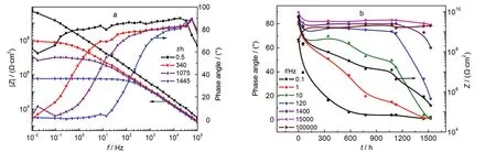
Fig.2 EIS of the coating sample exposed to the salt spray environment(T1) (a)Bode plots,(b)the variations of the phase angles at different frequencies and the coating impedance at 0.01 Hz(the asterisk curve)with time
The variations of the coating impedance at 0.01 Hz and the phase angles at different frequencies with exposure time are shown in Fig.2b.It is seen that during the early stage of the spray test,the phase angles measured at low and middle frequencies reduced quickly.After this stage the phase angles changed more slowly.Similar varying tendency could be observed for the coating impedance with exposure time(the curve with asterisk symbols).Three stages may be observed on the coating impedance curve:rapid decrease in the early stage, relatively slow decrease in the middle stage,and again quick decrease,which reflect the different stages of the coating degradation.21It is worth noting that in middle frequency range from 1 to 120 Hz,the variations of the phase angles and coating impedance show similar tendencies.Particularly,the variation of the phase angle at 10 Hz is very close to the variation in the coating impedance,and the different stages on the phase angle curve are also seen.About 1100 h later,both the coating impedance and the phase angle showed quicker decrease.After 1445 h,the coating impedance decreased to 6×10⁵Ω·cm2,while the phase angle at 10 Hz correspondingly decreased below 10°. This result suggests that the variation of phase angle at a certain frequency may reflect the variation of coating impedance and the coating performance.
The above phenomena may be explained by following analysis.Generally,for organic coating systems,the equivalent circuit in Fig.3 is well accepted.5,12Rsis the solution resistance,Ccis the coating capacitance,Rcis the coating pore resistance, while Rct,Cdl,and ZWrespectively stand for the charge transfer resistance,the double layer capacitance,and the Warburg impedance which reflect states of the electrochemical reactions under the coating.At the beginning,the coating resistance Rcis very high and the parameters Rct,Cdl,and ZWmay be neglected. If solution resistance Rsis also negligible,during the early period the equivalent circuit shown in Fig.3 may be approximately expressed as a parallel connection of Rcand Cc.
In such a case,the phase angle Φ of the impedance is:

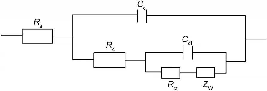
Fig.3 General equivalent circuits for coatings
This equation indicates that for coatings without macro-defects,the measured phase angle Φ is related to the applied current frequency ω,coating capacitance Cc,and coating resistance Rc.If ω value,which is across several orders of magnitude during EIS measurement,is very high(high frequency)or very low(low frequency)compared with the values of Ccand Rc,the product of ωCcRcwould be mainly determined by the ω value and the phase angle Φ would be high or low,as shown in Fig.2b.However,in middle frequency range,the product of CcRcwould obviously influence the value of tanΦ.During the exposure of the coating in corrosive environments,the electrolytes permeate into the coatings,resulting in the increase of the coating capacitance and the decrease of the coating resistance. However,the decrease of the coating resistance is usually much greater than the increase of the coating capacitance. Therefore,in middle frequency range the variations of the phase angles are mainly controlled by the variations of the coating resistance and show continuously decrease.During the early period in corrosive environments,the coating provides good protection and the coating impedance at low frequency(0.01 Hz for example)is mainly composed of the coating resistance Rcand the solution resistance Rswhich may be neglected,10hence the variation tendencies of phase angles at middle frequencies,from a few to dozens hertzs,are similar to that of the coating impedance.For the present coating system,the variation curve of the phase angle at 10 Hz is very close to that of the coating impedance,as shown in Fig.2b.
3.2 EIS results of the coating samples in NaCl solution(T2)
Fig.4 shows EIS spectra of the coating samples immersed in 3.5%NaCl solution at different time.During the early immersion stage,the coating impedance value was higher than 109Ω· cm2in low frequency domain of the Bode plot(Fig.4a).As immersion time prolonged,the coating impedance gradually decreased and the phase angles in lower frequency range also de-creased obviously.

Fig.4 EIS of the coating sample immersed in 3.5%NaCl solution(T2) (a)Bode plots,(b)the variations of the phase angles at different frequencies and the coating impedance at 0.01 Hz(the asterisk curve)with time
The variations of the coating impedance and phase angles at different frequencies with time are shown in Fig.4b.During the early immersion stage,both the phase angles measured at different frequencies and the coating impedance reduced quickly. But after the early stage the phase angles remained relatively stable with time,and similar tendency is observed for the coating impedance.It is seen that after 12000 h of immersion the coating impedance still remained above 108Ω·cm2,showing excellent performance.The barrier effect provided by the corrosion products of zinc particles in the zinc rich primer may play a role in keeping the coating impedance stable.7,8Although the coating performance is quite different from that under salt spray condition,the variation of the phase angle at 10 Hz is still very similar to the variation of the coating impedance with time.After 12000 h of immersion,the phase angles were around 80°.
3.3 EIS results of the coating samples in NaCl solution under UV lamp(T3)
Fig.5a shows the Bode plots of coating samples at different immersion time in 3.5%NaCl solution under UV light.The application of ultraviolet light significantly accelerates failure process of the coating system.After only 195 h of test,the coating impedance has decreased below 105Ω·cm2,which means that the protection of the coating was almost deteriorated. Meanwhile the phase angles in low and middle frequency ranges also decreased below 10°.Fig.5b shows the variations of the coating impedance and phase angles at different frequencies with testing time.The variations in phase angles in middle frequency range and the coating impedance again show similar tendencies.After 160 h of test,the coating impedance decreased quickly,and the phase angle at 10 Hz also showed quick reduce during the same time.
3.4 EIS results of the coating samples in simulated sultry environment(T4)
Fig.6a shows the Bode plots of coating samples at different exposure time in simulated sultry environment,and Fig.6b shows the variations of the coating impedance and phase angles at different frequencies.It is seen from Fig.6b that before 180 h the coating impedance decreased quickly,and from 180 to about 400 h the impedance remained a stable value.After 400 h the impedance decreased again.After the sample was exposed in the environment for 778 h,the coating impedance decreased from 109Ω·cm2to about 105Ω·cm2,which means failure of the coating performance.The phase angle at 10 Hz varies similarly to the coating impedance,and during the same period it decreased below 20°.

Fig.5 EIS of the coating sample immersed in 3.5%NaCl solution with UV lamp(T3) (a)Bode plots,(b)the variations of the phase angles at different frequencies and the coating impedance at 0.01 Hz(the asterisk curve)with time
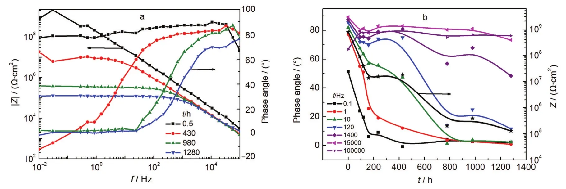
Fig.6 EIS spectra of the coating sample exposed to the simulated sultry environment(T4)(a)Bode plots,(b)the variations of the phase angles at different frequencies and the coating impedance(the asterisk curve)with time

Fig.7 Relationship between the impedance values at 0.01 Hz and the phase angles at 10 Hz
In Fig.7 the impedance value at low frequency,Z0.01Hz,is expressed as the function of the phase angle at 10 Hz,in order to observe the relationship between the two parameters.It is seen that for tests T1,T3,and T4,linear relationships between lg(Z0.01Hz)and Ф10Hzare observed and the correlation coefficients (R)are over 0.94.The data of T2 was not considered because during the whole test the Ф10Hzvalue showed only a small change.Therefore,the variations of Z0.01Hzand Ф10Hzare closely related.When Ф10Hzvalues are above 50°,the corresponding Z0.01Hzvalues are higher than 107Ω·cm2,which means that the protection of the coatings is fairly good.When Ф10Hzvalues are below 15°,the corresponding Z0.01Hzvalues are lower than 106Ω·cm2,indicating deterioration of the coatings.
Among the four corrosion environments tested,immersion in 3.5%NaCl solution under UV light(T3)is the most serious. With less than 240 h of exposure the coating impedance has reduced below 105Ω·cm2.The aging effect of the coatings by ultraviolet light significantly accelerates failure of the coating structure.The second serious corrosion environment is the simulated sultry environment(T4)where the coating impedance reduced to about 105Ω·cm2after 778 h of exposure.In the salt spray test(T1),it took about 1500 h for the coating impedance to decrease below 106Ω·cm2.The coating system shows excellent corrosion resistance in 3.5%NaCl solution at room temperature(T2).After 12000 h of immersion the coating impedance was still above 108Ω·cm2.
To understand the failure mechanisms of the coating system in different environments,FTIR analysis is carried out and the results are shown in Fig.8.The IR spectra of the samples tested in different environments are compared to the result of the sample immersed in 3.5%NaCl solution because after long time of immersion the coatings still remained good protection.In the figures,the absorption peaks at 1182 and 881 cm-1are formed by the stretching vibrations of C-F2bonds,the peak at 827 and 1456 cm-1are respectively due to the bending and stretching vibrations of C-F bonds,the peak at 1240 cm-1is due to the stretching vibration of C-O-C bonds in epoxy resin,and the peak at 1767 cm-1is the result of C=O stretching vibrations.22It is seen from Fig.8a that for the coating sample exposed in salt water plus ultra-violet light,the intensities of all the absorption peaks obviously decrease in contrast to the situation without UV radiation,indicating the breakdown of both fluorocarbon and epoxy structures.From Figs.8b and 8c,the peak intensities for samples exposed in the sultry and salt spray environments also decrease,but the changes are smaller, while the C=O peak at 1767 cm-1obviously intensified,which should be the result of decomposition of the macromolecules in epoxy structures.Usually fluorocarbon coatings show good resistance to UV because the very high bond energy.Deflorian et.al.23recently reported that the fluoropolymer coating is able to maintain high barrier properties after UV exposure,but the coating resistance reduces more quickly under salt spray testing condition.Hence,under the combined effect of UV and salt water,the failure of the C-F bonds is obviously accelerated.In the sultry and salt spray environments,the failure processes of the fluorocarbon and epoxy structures are slower,but still much quicker than in salt water.Temperature may also play an important role for failure of the coatings.The testing temperatures during the immersion+UV,sultry,salt spray,and immersion tests were around 58,45,35,and 20°C,respectively.This order is consistent to the failure rate of the samples.At higher temperature both the permeation of water and the breakdown of macromolecules are promoted.
Although the failure mechanisms of the coating system in the four environments are more or less different,the variations of the coating impedance with time show similar tendency.At the beginning the impedance decreases quickly,then it remains relatively stable for a period.After this stage a quick impedance decrease is again observed.It is interesting that for the tested system the variation of the phase angle at 10 Hz can reflect the variation of the coating impedance in different stages, despite the different failure processes in the four environments. This result is reasonable because the measured phase angles in middle frequency range are mainly determined by the variation of the coating impedance,despite the failure mechanism and failure rate.The coating impedance at low frequency,Z0.01Hz,is an important parameter reflecting the coating performance. However,to obtain the Z0.01Hzvalue for a coating system it usually takes several minutes or longer.While the phase angles in middle frequency range may be measured more quickly in contrast to the measurements for coating impedance or coating resistance.Therefore,the phase angle measurement may be used as a fast method to qualitatively evaluate coating performance for field inspection.
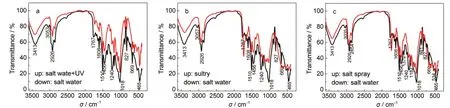
Fig.8 FTIR spectra for the samples after exposure tests in four different corrosive environments(a)salt water and salt water+UV light environments,(b)salt water and sultry environments,(c)salt water and salt spray environments
It should be pointed out that Eq.(1)is based on the hypothesis that the equivalent circuit of the coating system is a simple parallel connection of Rcand Cc.This is effective only for the early stage when the coatings have high impedances.In the later period of the test,corrosion may happen at the metal/coating interface and the equivalent circuit of the coating system would be more complicated.Hence the relationship between the coating resistance and phase angles would be different, which is worth to be further investigated.However,the experimental results show that the phase angles in middle frequency range varies very close to the impedance even in the later exposure stage.A possible explanation is that the contributions by the interface reaction parameters,such as the charge transfer resistance Rctand double layer capacitance Cdl,are still relatively small in the total impedance and may be cloaked by the coating resistance.7,24
4 Conclusions
(1)The failure processes of a multi-layer coating system (zinc-rich epoxy primer,epoxy middle coating with ferric oxide flakes,and fluorocarbon topcoat)in four corrosion environments were studied with EIS.The failure rate of the coating system in the four environments decreases in following order: immersion in 3.5%NaCl solution under UV light,steam above water surface at 45°C,salt spray at 35°C,and immersion in 3.5%NaCl solution at room temperature.
(2)Although the failure rates of the coating system in the four environments are different,as the test time prolongs,the variation tendencies of the phase angles at middle frequencies, from 1 to 120 Hz,are similar to that of the coating impedance. Particularly,for the studied system the variation of the phase angle at 10 Hz is very close to that of the coating impedance. When the value decreases below 15°,the corresponding coating impedance value is below 106Ω·cm2,indicating deterioration of the coating system.
(3)The phase angles in middle frequency range may be measured more quickly in contrast to the measurement for coating impedance at low frequency,hence may by used as qualitative evaluation parameters for field inspection of coatings.
(1) Scully,J.R.J.Electrochem.Soc.1989,136,979.
(2) Scully,J.R.;Hensley,S.T.Corrosion 1994,50,705.
(3)Van Westing,E.P.M.;Ferrari,G.M.;De Wit,J.H.W. Corrosion Sci.1994,36,979.
(4)Van Westing,E.P.M.;Ferrari,G.M.;De Wit,J.H.W. Corrosion Sci.1993,34,1511.
(5) Grundmeier,G.;Schmidt,W.;Stratmann,M.Electrochim.Acta 2000,45,2515.
(6) Marchebois,H.;Savall,C.;Bernard,J.;Touzain,S. Electrochim.Acta 2004,49,2945.
(7) Marchebois,H.;Joiret,S.;Savall,C.;Bernard,J.;Touzain,S. Surf.Coat.Tech.2002,157,151.
(8) Marchebois,H.;Keddam,M.;Joiret,S.;Savall,C.;Bernard,J.; Touzain,S.Electrochim.Acta 2004,49,1719.
(9) Barranco,V.;Feliu,S.,Jr.;Feliu,S.Corrosion Sci.2004,46, 2203.
(10) Philippe,L.V.S.;Lyon,S.B.;Sammon,C.;Yarwood,J. Corrosion Sci.2008,50,887.
(11) Raps,D.;Hack,T.;Wehr,J.;Zheludkevich,M.L.;Bastos,A. C.;Ferreira,M.G.S.;Nuyken,O.Corrosion Sci.2009,51, 1012.
(12) McIntyre,J.M.;Pham,H.Q.Prog.Org.Coat.1996,27,201.
(13) Bierwagen,G.P.;He,L.;Li,J.;Ellingson,L.;Tallman,D.E. Prog.Org.Coat.2000,39,67.
(14) Macedo,M.C.S.S.;Margarit-Mattos,I.C.P.;Fragata,F.L.; Jorcin,J.B.;Pébère,N.;Mattos,O.R.Corrosion Sci.2009,51, 1322.
(15) Akbarinezhad,E.;Bahremandi,M.;Faridi,H.R.;Rezaei,F. Corrosion Sci.2009,51,356.
(16) Haruyama,S.;Sudo,S.Electrochim.Acta 1993,38,1857.
(17) Mansfeld,F.;Tsai,C.H.Corrosion 1991,47,958.
(18) Mahdavian,M.;Attar,M.M.Corrosion Sci.2006,48,4152.
(19) Mehta,N.K.;Bogere,M.N.Prog.Org.Coat.2009,64,419.
(20) Zuo,Y.;Pang,R.;Li,W.;Xiong,J.P.;Tang,Y.M.Corrosion Sci.2008,50,3322.
(21) Miscovic-Stankovic,V.K.;Drazic,D.M.;Teodorovic,M.J. Corrosion Sci.1995,37,241.
(22) Wu,J.Technology and Applications of Fourier Transform Spectroscopy;Sci.Techn.Literature Pub.:Beijing,1994;pp 256-310.
(23) Deflorian,F.;Rossi,S.;Fedel,M.Corrosion Sci.2008,50,2360.
(24) Loveday,D.;Peterson,P.;Rodgers,B.JCT Coatings Tech. 2004,1,88.
December 30,2011;Revised:February 17,2012;Published on Web:February 27,2012.
Electrochemical Impedance Spectroscopy Study of Failure Process of an Epoxy/Fluorocarbon Coating System
PANG Ran ZUO Yu*TANG Yu-Ming XIONG Jin-Ping
(Key Laboratory of Carbon Fibers and Functional Polymers,Ministry of Education,School of Materials Science and Engineering, Beijing University of Chemical Technology,Beijing 100029,P.R.China)
The failure processes of a multi-layer coating system(zinc-rich epoxy primer,epoxy middle layer,and fluorocarbon topcoat)in four corrosion environments were studied with electrochemical impedance spectroscopy(EIS).The failure rate of the coating system in the four environments decreases in following order:immersion in a 3.5%NaCl solution under UV light,steam above a water surface at 45°C, salt spray at 35°C,and immersion in a 3.5%NaCl solution at room temperature.Although the failure rates of the coating system in the four environments are different,the variations of the phase angles at the middle frequency range,particularly 10 Hz,are very close to that of the coating impedance;hence they may be used as a qualitative evaluation parameter for coating inspection.
Fluorocarbon coating;Electrochemical impedance spectroscopy;Performance; Failure;Fast evaluation;Phase angle
10.3866/PKU.WHXB201202272
O646;TG174
∗Corresponding author.Email:zuoy@mail.buct.edu.cn;Tel/Fax:+86-10-64423795.
The project was supported by the National Key Technologies R&D Program of China(2007 BAB 27 B04).
国家科技支撑计划项目(2007 BAB 27 B04)资助