永磁电机研究的新进展
2012-09-16诸自强
1 Introduction
A major feature of permanent magnet(PM) machines,in addition to high power/torque density and high efficiency, is that there are numerous PM machine topologies, each of which may be found to be more suitable for one specific application. Before 1980s, some pioneering work was carried out on PM machines,primarily based on ferrite magnets[1-5]. However, over last 30 years, there have been significant advances on magnetic materials, electrical machines, power electronics,microprocessors and controls. Most notably, NdFeB magnet[6], IGBT[7], space-vector PWM[8], direct torque control[9-11], and in addition to switched reluctance machines[12], surface-mounted PM (SPM) and interior PM(IPM) machine topologies[13-19]were developed and/or investigated in 1980s. They continue for further improvement[20-24], while many new and novel PM machine topologies are still emerging and being developed.
This paper briefly overviews some novel PM brushless machine topologies, their features and applications, as well as some research activities which are being undertaken world-wide on applications of PM machines to various market sectors.
2 Current states and general trends
For electrical machines and drives over last 30 years,PM brushless machines become more popular for numerous applications, ranging from domestic appliances,electric vehicles/hybrid electric vehicles[25,26], more electric aircrafts[27], to wind power generations[28].
In general, the power and torque rating of a PM machine can now be much higher, so does the power and torque density. It was used to consider PM machines to be only suitable for applications which require a few hundred watts to a few kilowatts, it is now possible for the PM machines to produce power of hundred kilowatts upto several megawatts. Fig.1 shows 5MW, 147r/min PM wind generator made by Prokon Nord and 18MW PM ship propulsion machine made by DRS technologies,respectively.
Meanwhile, the operation speed can now reach over 100kr/min with added benefits of light weight and use of less expensive rare-earth magnets[29-35]. Fig.2 shows Dyson’s hand held vacuum cleaner which employs a 100kr/min PM motor.
For low speed (10~20r/min) direct-drive wind power generators of several megawatts are commercially in operation with high reliability. Fig.3 shows Siemens’3MW direct-drive wind power PM generator.
It is now fully aware that system level integration and design consideration are one of the key technologies[25]. Various design considerations at the machine/drive levels and system levels should be taken into account. Otherwise the PM machine may not be able to satisfy the system requirement and/or the drive and controller cannot fully exploit the potential capacity which a PM machine can offer. Fig.4a shows a typical FUDS driving cycle, while Fig.4b clearly shows that there is a mismatch between the motor’s high efficiency region and electric vehicle(EV)’s most frequently operating regions, and hence there is a need to match them well so as to extend the EV’s driving distance, as well be discussed further later. Another good example is the influence of PM machine topologies, cross-coupling effect, inverter non-linearity, and control strategies on sensorless controlled performance of the drives[36-40].

Fig.1 Examples of high power PM machines

Fig.2 Dyson handheld vacuum cleaner using 100kr/min PM motor
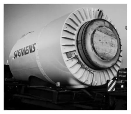
Fig.3 Siemens’ 3MW direct-drive PM wind power generator

Fig.4 Mismatch between machine high efficiency region and EV driving cycles
Conventional SPM and IPM machines with distributed windings and their controls in brushless DC(BLDC) operation and brushless AC(BLAC)operation including vector and direct torque controls in the constant torque and constant power regions now became more mature[20-22,41-47], being extensively used for domestic appliances, servo, EV/HEV and wind power generation application.
By way of example, it is shown in that for EV/HEV application[25], the maximum achievable output power and torque when a machine is operated in the BLAC mode are higher than that which can be achieved when the same machine is operated in 2-phase, 120°elec. conduction BLDC mode, irrespe-ctive of whether it has a trapezoidal or sinusoidal back-emf waveform. At high speed, the phase current waveform will approximate to a sinusoid even in a BLDC drive, due to the influence of the winding reactance, while any harmonics in the back-emf waveform will cause the flux-weakening performance to deteriorate. However, by employing a 3-phase, 180oelec. BLDC conduction strategy (6-step operation)together with phase control[42], the high speed power capability of the machine can be improved, although below base-speed its torque capability is reduced.
SPM brushless machines which have a fractional number of slots per pole per phase and a concentrated winding, either single layer or double layer, have been the subject of recent research[24,48-50]. They have inherently low cogging torque, short end-windings and, hence, low copper loss, high efficiency, and high power density, as well as better flux-weakening performance[51]. Such machines were extensively used for BLDC drives in 1980s[20]and are now seriously considered for BLAC drives application[23,24].
In fractional-slot, single layer, concentrated winding PM machines, the phase windings are effectively isolated, both magnetically and physically,and a high per-unit self-inductance can readily be achieved to limit the prospective short-circuit current,by utilizing relatively high airgap inductance and leakage flux at slot openings[49-53]. Due to the physical separation of the coils and the negligible mutual-inductance between phases, the possibility of a phase-to-phase fault is minimized. Therefore, the fault tolerance and flux-weakening capability of such machines can be significantly higher than for more conventional machine designs. Hence, such type of fault-tolerant PM machines driven by a single or multi-3-phase inverters have been developing for applications which require a high fault-tolerant capability, such as aerospace.
Since in fractional-slot PM machines the torque is developed by the interaction of a stator space harmonic mmf with the permanent magnets a relatively high rotor eddy current loss can result from the fundamental and low order space harmonic mmfs which rotate relative to the rotor. The magnets can be segmented to reduce the eddy current loss.
In general, fractional slot, concentrated winding SPM and IPM machines have attracted intensive research, Fig.5~Fig.8. The reluctance torque component will be significantly reduced or even negligible when an IPM rotor is employed. The most challenge is the rotor eddy current loss and protection of irreversible demagnetization. Many new types of PM machine topologies have been emerged and will be briefly reviewed in the next few sections.
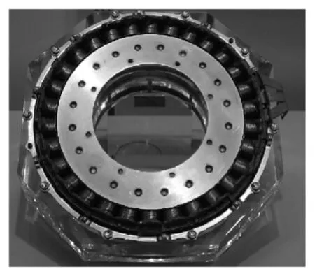
Fig.5 Toyota/Aisin HEV PM machine

Fig.6 22-pole, 24-slot, 3-phase PM torque-boost machine

Fig.7 Bosch battery powered lawn mower using SPM motor

Fig.8 Panasonic air conditioner compressor using IPM motor
3 Halbach magnetized PM machines[75]
Halbach magnetized PM machines, Fig.9, in which a self-shielding, sinusoidal magnetization is employed[75,76], result in: ①An essentially sinusoidal airgap field distribution, which is desirable for low stator iron loss (conducive for high efficiency and suitable for high-speed operation), sinusoidal backemf waveform (most appropriate for brushless AC motors), and negligible cogging torque (low torque ripple and low acoustic noise and vibration). ②The rotor back-iron is not essential due to self-shielding magnetization so that the rotor mass and inertia can be reduced, which is conducive to good dynamic performance. ③Skew is not required in order to obtain sinusoidal back-emf waveform for brushless ac motors and to eliminate cogging torque, which is very attractive for low cost manufacturing. ④Concentrated non-overlapping stator winding can be employed,which results in a shorter end-winding, high torque density, low copper loss and high efficiency. ⑤A higher airgap flux density is possible and appropriate for slotless machines or slotted machines which need a large airgap.

Fig.9 4-pole Halbach magnetized magnet
In an ideal Halbach magnetized magnet ring,Fig.9a, the radial and circumferential magnetization distributions vary sinusoidally and cosinusoidally.When a Halbach magnetised magnet is realised from discrete magnet segments, usually sinterred NdFeB or SmCo, Fig.9b, the ideal magnetization distribution is approximated. As the number of magnet segments per pole is increased (typically 3~4) the airgap field distribution and back-emf waveform can become more sinusoidal and the cogging torque is reduced.
The concept of Halbach magnetisation may be extended and utilised to reduce the flux leakage and enhance the airgap field in various PM machine topologies, as shown in Fig.10.
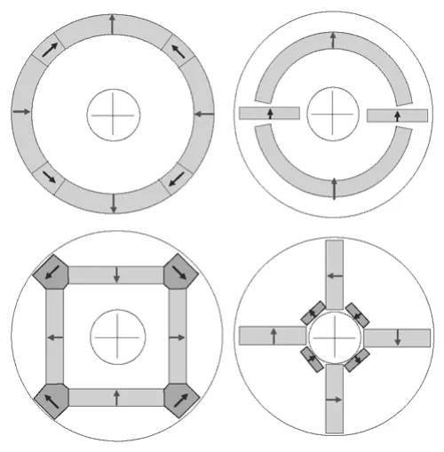
Fig.10 Halbach concept for reduction of flux leakage
Halbach magnetized PM machines have been developed for various applications, ranging from flywheel motor and generator, servo motor, electric assisted power steering, electric vehicles, aerospace,wheelchair, etc. By way of example, Fig.11 shows Halbach motor made by Aisin Seiki, and was adopted for the position control unit used in the Toyota’s advanced i-REAL personal mobility vehicle.
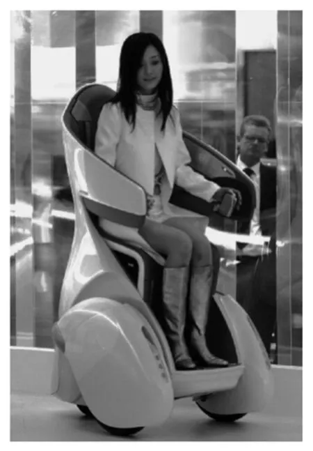
Fig.11 Toyota’s advanced i-REAL personal mobility vehicle
4 Variable flux PM machines
The major advantages of PM machines are high torque/power density and high efficiency. However, PM machines also have the disadvantages of non-adjustable flux and potential irreversible demagnetisation, as well as expensive and also limited rare-earth magnet resources.
Variable-flux PM (VFPM) machines are those which include some means of adjusting the level of PM flux and are of interest today as they allow flexibility in terms of optimizing efficiency across a machine operation cycle, enhancing low speed torque, extending high speed operation range, and reducing the likelihood of an excessively high back-emf being induced at high speed in the event of an inverter fault when a PM machine is operating in the flux-weakening region.
There are many examples of VFPM machines,Fig.12, including hybrid-excited machines with field coils[54-63], machines with mechanical adjustment[64],or those that involve other means of varying the flux,such as memory machine[65]. Further, in the case of hybrid-excited machines by the nature of PM and coil excitation flux paths, series or parallel, and the location of coil excitation source, on stator or rotor.For example, in hybrid synchronous PM machines,Fig.13a, both are on the rotor, and in hybrid doubly salient PM machines both are on the stator, Fig.13b,while the consequent pole PM machine has the rotor mounted magnets and stator mounted coils, Fig.13c.Although series excitation is simple it requires a higher excitation mmf due to the low recoil permeability of the magnets. On the other hand,parallel excitation is more effective electromagnetically but leads to a more complex machine structure.Coil excitation on the stator is preferable since it does not require brush/slip-ring as required in the case of coil excitation on the rotor. Fig.14 shows a novel hybrid- excited switched flux PM machine and its variable flux characteristics[63].
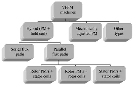
Fig.12 Categorization of VFPM machines

Fig.13 Examples of hybrid-excited machines
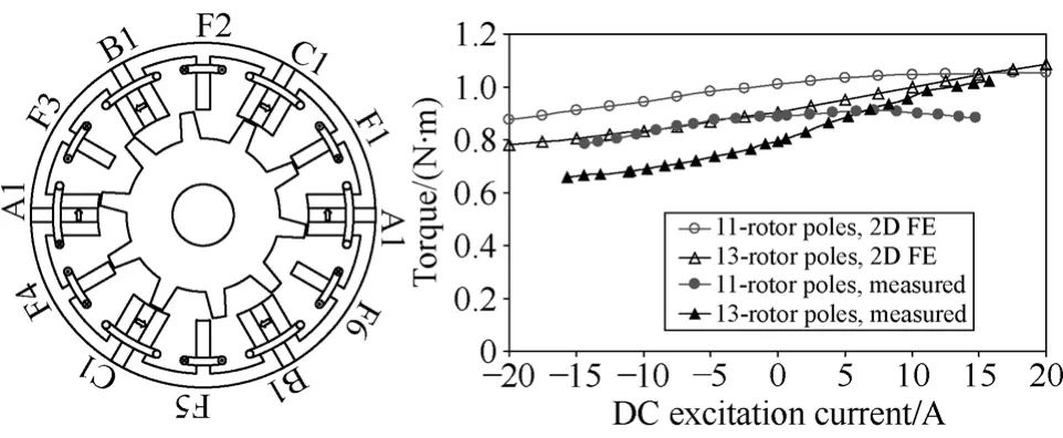
Fig.14 Novel hybrid-excited switched flux PM machine[63]
Unlike hybrid-excited machines, mechanically adjusted VFPM machines have only PM excitation,but the flux is varied by mechanical adjustment, either involving additional actuation, or by utilizing torque or speed dependant mechanisms. Many different topologies are available, a few examples being shown in Fig.15[64].

Fig.15 Mechanically adjusted VFPM machines[64]
The major disadvantages of hybrid excited machines are that it needs an extra dc power supply and the coil excitation produces extra copper loss. It is usually much easier to weaken the flux but difficult to enhance the flux due to magnetic saturation and significantly weaker coil excitation than PM excitation. For mechanically adjusted VFPM machines, it needs an extra actuation system which makes the system more complex.
There are also other VFPM machines which do not fit neatly into the categories above, most notably,memory motors[65,66], Fig.16. Unlike the conventional PM machines, variable flux memory motors are capable of changing the magnetization intensity of typically Alnico magnets by a pulse current through the stator windings for a very short time duration and memorizing the flux density level in the rotor magnets.They have potential advantages, such as simple structure, high efficiency, large starting torque, and wide operation speed range. Therefore, they have significant potential.

Fig.16 Memory machine[65]
5 Hybrid PM machines[25,26]
PM can be integrated into any other types of machine technologies, such as induction machines,switched reluctance machines(SR), synchronous reluctance machines (SynR), wound field synchronous machines(i.e. hybrid excited machines which are described in the previous section), etc, but it will primarily have PM machine characteristics as long as there is PM.
The earliest one combines induction and PM machines for line-starting, Fig.17. The main feature is that it is a low cost solution for starting without the need of an inverter. However, during starting the PMs produce a braking torque and the motor exhibits significant torque oscillation.

Fig.17 Hybrid PM & induction machines
The torque density can be enhanced by increasing the saliency ratio. Multiple layers of magnets[67-71], which integrate the SynR and PM machine technologies, Fig.18, may be employed to increase the saliency ratio, although, in practice, the number of layers is usually limited to 2 or 3[67].Meanwhile, the concept of PM assisted reluctance machine[70,71]can be utilized to reduce the amount of expensive NdFeB magnets or eliminate NdFeB magnets by employing ferrite magnets, while a wide flux-weakening capability and a high torque density is maintained, without the risk of generating an excessive back-emf should an inverter fault occur at high speeds.
The short-duration torque capability is determined primarily by the demagnetization withstand capability of the magnets and the level of magnetic saturation.Reducing the d- and q-axis cross-coupling magnetic saturation by incorporating air flux barriers in q-axis,Fig.19, can enhance the overload capability[25], while its effect on d-axis flux is minimal, but the overload torque capability in constant torque operation range is significantly enhanced. However, reduction of the cross-coupling magnetic saturation in this way may also reduce the saliency ratio and consequently the reluctance torque. If the q-axis flux barrier is too large,d-axis inductance may become larger than q-axis inductance, and consequently, negative reluctance torque may exist in the flux-weakening operation,although in this case, it may be advantageous for high frequency signal injection based sensorless control.
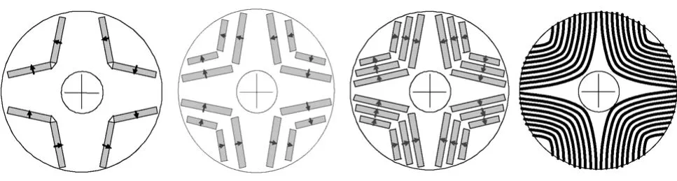
Fig.18 Hybrid PM and SynR rotors

Fig.19 Hybrid PM and SynR rotors with q-axis flux barriers
When the PMs are located on the stator, the rotor must have salient pole geometry, similar to that of an SR machine, which is simple and robust, and suitable for high-speed operation[25,72-74]. The stator carries a non-overlapping winding. The PMs can be mounted in the stator back-iron (doubly salient PM machines[72]),placed on the inner surface of the stator teeth (flux reversal PM machines[73]), or sandwiched in the stator teeth (switched flux PM machines[74]), Fig.20.Irrespective of their location, however, the torque results predominantly from the PM excitation torque,i.e. the reluctance torque is negligible, although the torque production mechanism relies on the rotor saliency. Compared with conventional PMM topologies, it is easier to limit the temperature rise of the magnets as heat can be removed more easily from the stator.
A major disadvantage for doubly-salient PM machines[72]is that due to unipolar flux-linkage, the torque density is relatively low. This is significantly improved in switched flux PM machines, Fig.21a, in which flux-focusing may be readily incorporated[74],while the phase flux-linkage waveform is bipolar, the torque capability is significantly higher than that of a doubly-salient PM machines. Meanwhile, the back-emf waveform of switched-flux PM machines is essentially sinusoidal, which makes them more appropriate for brushless AC operation. Conventional switched flux PM machines use a high number of PMs,Fig.21a. It is possible to reduce the number of PMs by half, while maintaining its torque capability, Figs. 21b and 21c.

Fig.20 Hybrid PM and SR machines having PMs on stator
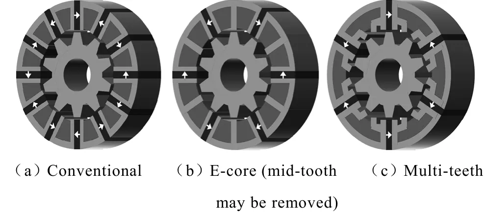
Fig.21 Hybrid PM and SR machines
6 Other types of novel PM machines
There are numerous other types of PM machines,from rotary and linear/tubular, radial field and axial field, spherical and 2-dimensional planar, to soft magnetic composite[77]and transverse flux PM machines[78,79], it is impossible to review all of them in this paper due to space limit. Here, only dual-rotor PM machines[80]and magnetic geared PM machines[81]will be briefly described.
A dual-mechanical-port machine[80], Fig.22, has three parts, one stator, two rotors and two airgaps. The electromagnetic torque of the centre part is the sum from both inner and outer airgaps. Two rotors can be assigned arbitrary among the three although certain assignment of movable parts may be more favourable than the others in terms of construction, control and application. Two rotors have independent mechanical speeds and torque that are determined by the connected external loads, e.g. IC engine and wheel shaft via a gear box. Hence, it is eminently suitable for HEV application. A dual-rotor PM machine is a special type of dual-mechanical-port machine. It may be considered as a double-fed wound-field induction machine with a permanent magnet rotor being sandwiched between its stator and rotor. Fig.23 shows an example of dual-rotor PM machine used for HEV application. Its disadvantages include complex mechanical structure and the need of brushes/slip rings to supply the power to the rotor.

Fig.22 Dual-mechanical-port machine[80]

Fig.23 Dual-rotor PM machine and its application to HEV(provided by Prof. Ping Zheng at HIT)
A magnetic gear also consists of 3 components: 2 free to rotate, the 3rd one mechanically earthed. The high and low speed PM rotors have lower and higher pole numbers, respectively, while intermediate rotor consists of iron poles, Fig.24. The ferromagnetic pole-pieces between two rotors serve to modulate the magnetic field which is produced by the permanent magnets on each rotor. In this way, each rotor produces a dominant asynchronous space harmonic having the same pole number as the other rotor to facilitate torque transmission and gearing. The gear ratio depends on the number of pole-pairs on each rotor and the number of ferromagnetic pole-pieces. It provides high torque transmission capability, inherent overload protection, and physical isolation between input and output shafts. Magnetically geared PM machine[81]can also be considered as a special type of dual-mechanical-port machine. It uniquely combines a magnetic gear within the space envelope of a brushless PM machine by attaching one of the PM rotors of the magnetic gear onto the stator of brushless machine, thus it allows to use high speed PM machines for low speed application (such as wind power generation), or vice verse. According to the operation principle of a dual-mechanical-port machine,it is possible to remove the PMs on the stator to significantly reduce the amount of PMs although in this case its torque density is found to be reduced.
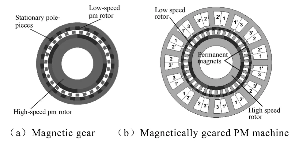
Fig.24 Magnetic geared PM machine
7 Conclusions
Over last 30 years, we have witnessed significant advances on magnetic materials, electrical machines,power electronics, microprocessors and controls, most notably, NdFeB magnet, IGBT, space-vector PWM,direct torque control, and digital signal processor. PM brushless machines have high power/torque density and high efficiency, and are now used extensively in different market sectors. Many new and novel machine topologies have been developed and are still emerging. Some of them are briefly reviewed in this paper.
There are still many challenges and opportunities.Rare-earth PMs are still relatively expensive and there are concerns about their resources and prices. Hence,further significant improvements in PM machines should be expected, while some “magnetless”machines, using no magnet or less magnet, are being seriously investigated, including more conventional induction machines, switched and synchronous reluctance machines, as well as wound field machines.
AcknowledgmentThe author thanks the financial support by the Engineering and Physics Science Research Council, UK, Ref. EP/F016506/1, and also his colleagues and PhD students at the University of Sheffield, UK.
This paper is based on the author’s Keynote Speech verbally presented at IEEE International Electric Mchines and Drives Conference (IEMDC 2011), May 16-18, 2011, Niagara Falls, Canada.
[1]Merrill F W. Permanent magnet excited synchronous motor[J]. IEE Trans., 1955, 74: 1754-1760.
[2]Honsinger V P. Performance of polyphase permanent magnet machines[J]. IEEE Trans. Power Apparatus and Systems, 1980, 99(4): 1510-1518.
[3]Binns K J, Barnard W R, Jabbar M A. Hybrid PM synchronous motors[J]. Proc. IEE-B, 1978, 125(3):203-208.
[4]Binns K J, Jabbar M A, Parry G E. Choice of parameters in hybrid PM synchronous motor[J]. Proc.IEE, 1979, 126(8): 741-744.
[5]Miyashita K, Yamashita S, Tanabe S, et al.Development of a high speed 2-pole permanent magnet synchronous motor[J]. IEEE Trans. on PAS,1980, 99(6): 2175-2181.
[6]Parker. R J Advances in permanent magnetism[M].New York: John Wiley&Sons, 1990.
[7]Bose B K. Power electronics and variable frequency drives[M]. New York: IEEE Press, 1997.
[8]Broeck H W van Der, Skudelny H C, Stanke G V.Analysis and realization of a pulsewidth modulator based on voltage space vectors[J]. IEEE Trans. Ind.Appl., 1988, 24(1): 142-150.
[9]Takahashi, Toshihiko N. A new quick-response and high-efficiency control strategy of an induction motor[J]. IEEE Trans. Ind. Appl., 1986, 22(5): 820-827.
[10]Depenbrock M. Direct self-control of inverter-fed induction machine[J]. IEEE Trans. Power Electronics,1988, 3(4): 420-429.
[11]Vas P. Sensorless vector and direct torque control[M].Oxford: Oxford University Press, 1998.
[12]Lawrenson P J, Stephenson J M, Blenkinsop P T, et al.Variable-speed switched reluctance motors[J]. Proc.IEE-B, 1980, 127(4): 253-265.
[13]Binns K J, Wong T M. Analysis and performance of a high-field PM synchronous machine[J]. Proc. IEE-B,1984, 131(6): 252-258.
[14]Rahman M A, Little T A. Dynamic performance analysis of permanent magnet synchronous motors[J].IEEE Trans. Power Apparatus and Systems, 1984,103(6): 1277-1282.
[15]Jahns T M. Torque production in permanent magnet synchronous motor drives with rectangular current excitation[J]. IEEE Trans. Ind. Appl., 1984, 20(4)803-813.
[16]Chalmers B J, Hamed S A, Baines G D. Parameters and performances of a high-field PM synchronous motor for variable frequency operation[J]. Proc.IEE-B, 1985, 132(3): 117-124.
[17]Uddin M N, Radwan T S, Rahman M A. Performance of interior permanent magnet motor drive over wide speed range[J]. IEEE Trans. Energy Conversion, 2002,17(1):79-84.
[18]Rahman M A, Little T A, Slemon G R. Analytical models for interior-type PM synchronous motors[J].IEEE Trans. Magnetics, 1985, 21(5): 1741-1743.
[19]Jahns T M, Kliman G B, Newmann T W. Interior permanent magnet synchronous motors for adjustablespeed drives[J]. IEEE Trans. Ind. Appl., 1986, 22(4):738-747.
[20]Kenjo T, Nagamori S. Permanent magnet and brushless DC motors[M]. Oxford: Clarendon Press, 1985.
[21]Hendershot J R, Miller T J E. Design of brushless permanent magnet motors[M]. Oxford: Magna Physics Publishing & Clarendon Press, 1994.
[22]Gieras J F, Wing M. Permannet magnet motors technology-design and application[M]. 2nd ed. New York: Marcel Dekker, 2002.
[23]Takeda Y, Matsui N, Morimoto S, et al. Design and analysis of interior permanent magnet synchronous motors[M]. Tokyo: Ohmsha, 2001.
[24]Bianchi N. Theory and design of fractional-slot PM machines[M]. Padova: CLEUP, 2007.
[25]Zhu Z Q, Howe D. Electrical machines and drives for electric, hybrid, and fuel cell vehicles[J].Proc. IEEE,2007, 95(4): 746-765.
[26]Zhu Z Q, Chan C C. Electrical machine topologies and technologies on electric, hybrid, and fuel cell vehicles[C]. IEEE Vehicle Power and Propulsion Conf. (VPPC), Keynote Speech- KN3, Paper No:H08787, 2008: 1-6.
[27]Mecrow B C, Jack A G, Atkinson D J, et al. Design and testing of a four-phase fault-tolerant permanentmagnet machine for an engine fuel pump[J]. IEEE Trans. Energy Conv., 2004, 19(4): 671-678.
[28]Polinder H, F F A van der Pijl, G J de Vilder, et al.Comparison of direct-drive and geared generator concepts for wind turbines[J]. IEEE Trans. Energy Conv., 2006, 21(3): 725-733.
[29]Hesmondhalgh D E, Tipping D, Amrani M. Design and construction of a high-speed high performance direct-drive hand piece[J]. Proc. IEE-B, 1987, 134:286-294.
[30]Ede J D, Zhu Z Q, Howe D. Rotor resonances of high-speed permanent-magnet brushless machines[J].IEEE Trans. Ind. Appl., 2002, 38(6): 1543-1548.
[31]Paulides J H, Jewell G W, Howe D. An evaluation of alternative stator lamination materials for a highspeed, 1.5MW, permanent magnet generator[J]. IEEE Trans. Magnetics, 2004,40(4):2041-2043.
[32]Zhu Z Q, Ede J D, Howe D. Design of high-speed brushless dc motors for sensorless operation[C]. Proc.16th Int. Conf. on Electrical Machines, ICEM 2004,Cracow, Poland, Paper No: 235, CD ROM.
[33]Bianchi N, Bolognani S, Luise F. Analysis and design of a PM brushless motor for high-speed operations[J].IEEE Trans. Energy Conv., 2005, 20(3): 629-637.
[34]Binder A, Schneider T, Klohr M. Fixation of buried and surface-mounted magnets in high-speed permanent-magnet synchronous machines[J]. IEEE Trans.Ind. Appl., 2006, 42(4): 1031-1037.
[35]Kolondzovski Z, Arkkio A, Larjola J, et al. Power limits of high-speed permanent-magnet electrical machines for compressor applications[J]. IEEE Trans.Energy Conv., 2011, 26(1): 73-82.
[36]Guglielmi P, Pastorelli M, Vagati A. Cross saturation effects in IPM motors and related impact on zerospeed sensorless control[J]. IEEE Trans. Ind. Appl,2006, 42 (6): 1516-1522.
[37]Bianchi N, Bolognami S, Jang J H, et al.Comparison of PM motor structures and sensorless control techniques for zero-speed rotor position detection[J].IEEE Trans. Power Electronics, 2007, 22(6): 2466-2475.
[38]Li Y, Zhu Z Q, Howe D, et al. Improved rotor position estimation by signal Injection in brushless AC motors, accounting for cross-coupling magnetic saturation[J]. IEEE Trans. Ind. Appl., 2009, 45(5):1843-1849.
[39]Zhu Z Q, Gong L M. Investigation of effectiveness of sensorless operation in carrier signal injection-based sensorless control methods[J]. IEEE Trans. Industrial Electronics, 2011, 58(8): 3431-3439.
[40]Gong L M, Zhu Z Q. Modeling and compensation of inverter nonlinearity effects in carrier signal injection-based sensorless control methods from positive sequence carrier current distortion[J]. IEEE Trans. on Ind. Appl., 2011, 47(3): 1283-1292.
[41]Jahns T M. Flux-weakening regime operation of an interior permanent magnet synchronous motor drive[J]. IEEE Trans. Ind. Appl., 1987, 23(4): 681-689, 1987.
[42]Bose B K. A high-performance inverter-fed drive system of an interior permanent magnet synchronous machine[J].IEEE Trans. Ind. Appl., 1988, 24(6):987-997.
[43]Schiferl R, Lipo T A. Power capability of salient pole permanent magnet synchronous motors in variable speed drive[J]. IEEE Trans. Ind. Appl., 1990, 26(1):115-123.
[44]Soong W L, Miller T J E. Field-weakening performance of brushless synchronous AC motor drives[J]. Proc. IEE-EPA, 1994, 141: 331-340.
[45]Morimoto S, Sanada M, Takeda Y. Wide-speed operation of interior permanent magnet synchronous motors with high-performance current regulator[J].IEEE Trans. Ind. Appl., 1994, 30(4): 920-926.
[46]Morimoto S, Sanada M, Takeda Y. Inverter-driven synchronous motors for constant power[J]. IEEE Ind.Appl. Magazine, 1996, 2(6): 18-24.
[47]Vaez S, John V I, Rahman M A. An on-line loss minimization controller for interior permanent magnet motor drives[J]. IEEE Trans. Energy Conv., 1999,14(4): 1435-1440.
[48]Cros J, Viarouge P. Synthesis of high performance PM machines with concentrated windings[J]. IEEE Trans. Energy Conv., 2002, 17(2): 248-253.
[49]El-Refaie A M. Fractional-slot concentrated winding synchronous permanent magnet machines: opportunities and challenges[J].IEEE Trans. Industrial Electronics, 2010, 57(1): 107-121.
[50]Zhu Z Q. Fractional slot permanent magnet brushless machines and drives for electric and hybrid propulsion systems[J]. Int. Journal for Computation and Mathematics in Elec. and Elect. Eng. (COMPEL),2011, 30(1): 9-31.
[51]Refaie A M El, Jahns T M. Optimal flux-weakening in surface PM machines using concentrated windings[J].IEEE Trans. Ind. Appl., 2005, 41(3):790-800.
[52]Mecrow C, Jack A G, Haylock J A. Fault tolerant permanent magnet motors drives[J]. Proc. IEE-EPA,1996, 143(6): 433-437.
[53]Jack G, Mecrow B C, Haylock J A. A comparative study of permanent magnet and switched reluctance motors for high-performance fault-tolerant applications[J]. IEEE Trans. Ind. Appl., 1996, 32(4): 889-895.
[54]Spooner E, Khatab S A W, Nicolaou N G. Hybrid excitation of AC and DC machines[C]. Proc. IEE Int.Conf. Electrical Machines and Drives, 1989: 48-52.
[55]Sugii Y, Yada M, Koga S. Applicability of various motors to electric vehicles[C]. Proc. 13th Int. Electric Vehicles Symp., 1996: 757-764.
[56]Tapia J A, Leonardi F, Lipo T A. Consequent pole permanent magnet machine with field weakening capability[C]. Proc. IEEE Electric Machines and Drives Conference, 2001: 126-131.
[57]Chan C C, Zhang R, Chau K T, et al.A novel brushless PM hybrid motor with a claw-type rotor topology for electric vehicles[C]. Proc. 13th International Electric Vehicle Symposium, 1996, II: 579-584.
[58]Chan C C, Zhuang R, Chau K T, et al. Optimal efficiency control of PM hybrid motor drives for electric vehicles[C]. Proc. IEEE Power Electronics Specialists Conference, 1997: 363-368.
[59]Luo X, Lipo T A. A synchronous/permanent magnet hybrid AC machine[J]. IEEE Trans. Energy Conv.,2000, 15(2): 203-210.
[60]Leonardi F, Matsuo T, Li T Y, et al. Design considerations and test results for a doubly salient PM motor with flux control[C]. IEEE Ind. Appl. Society Annual Meeting, 1996: 458-463.
[61]Hoang E, Lecrivain M, Gabsi M. A new structure of a switching flux synchronous polyphased machine with hybrid excitation[C]. Proc. European Conf. Power Electronics and Applications, 2007: 1-8.
[62]Amara Y, Vido L, Gabsi M, et al. Hybrid excitation synchronous machines: energy efficient solution for vehicle propulsion[J]. IEEE Trans. Vehicular Technology, 2009, 58 (5): 2137-2149.
[63]Chen J T, Zhu Z Q, Iwasaki S, et al.A novel hybrid excited switched-flux brushless AC machine for EV/HEV applications[J]. IEEE Trans. Vehicular Technology, 2011, 60(4): 1365-1373.
[64]Owen R, Zhu Z Q, Wang J B, et al. Review of variable-flux permanent magnet machines[C]. Int.Conf. on Elec. Machines and Systems, 2011, Beijing,China, paper PS-PMM-60.
[65]Ostovic V. Memory motors[J]. IEEE Trans. Ind.Appl., 2003, 99(1): 52-61.
[66]Yu C, Chau K T. Design, analysis, and control of DC-excited memory motors[J]. IEEE Trans. Energy Conv., 2011, 26(2): 479-489.
[67]Honda Y, Higaki T, Morimoto S, et al, Rotor design optimisation of a multi-layer interior permanentmagnet synchronous motor[J]. Proc. IEE-EPA, 1998,145(2): 119-124.
[68]Soong W L, Staton D A, Miller T J E. Design of a new axially laminated interior permanent magnet motor[J].IEEE Trans. Ind. Appl., 1995, 31 (2): 358-367.
[69]Lipo T A. Synchronous reluctance machines-a viable alternative for AC drives? [J]. Electric Machines and Power Systems, 1991, 19(6): 659-671.
[70]Vagati, Pellegrino G, Guglielmi P. Design tradeoffs between constant power speed range, uncontrolled generator operation and rated current of IPM motor drives[C]. 2010 IEEE Energy Conversion Congress and Exposition (ECCE), 2010: 4107-4114.
[71]Armando, Guglielmi P, Pellegrino G, et al.Accurate magnetic modelling and performance analysis of IPM-PMASR motors[C]. 2007 IEEE Ind. Appl.Society Annual Meeting, 2007: 133-140.
[72]Liao Y, Liang F, Lipo T A. A novel permanent magnet machine with doubly salient structure[J].IEEE Trans. Ind. Appl., 1995, 3(5): 1069-1078.
[73]Deodhar R P, Andersson S, Boldea I, et al. The flux-reversal machine: a new brushless doubly-salient permanent-magnet machine[J]. IEEE Trans. Ind.Appl., 1997, 33(4): 925-934.
[74]Zhu Z Q, Chen J T. Advanced flux-switching permanent magnet brushless machines[J]. IEEE Trans.Magnetics, 2010, 46(6): 1447-1453.
[75]Zhu Z Q. Recent development of Halbach permanent magnet machines and applications[C]. The 4th Power Conversion Conference, JIEE, IEEE-IAS, 2-5 April 2007, Nagoya, Japan, 2007: K9-K16.
[76]Atallah K, Howe D. The application of Halbach cylinders to brushless AC servo motors[J].IEEE Trans Magnetics,1998,34(1):2060-2062.
[77]Jack A G, Mecrow B C, Dickinson P G, et al.Permanent-magnet machines with powdered iron cores and pre-pressed windings[J]. IEEE Trans.Ind. Appl., 2000,36(4):1077-1083.
[78]Weh H, May H. Achievable force densities for permanent magnet excited machines in new configurations[C]. Proc. Int. Conf. Electrical Machines, 1986: 1107-1111.
[79]Weh H, Hoffmann H, Landrath J. New permanent magnet excited synchronous machine with high efficiency at low speed[C]. Proc. Int. Conf. Electrical Machines, 1988: 1-6.
[80]Xu L Y. A new breed of electric machines - basic analysis and applications of dual mechanical port electric machines[C]. Keynote Speech, International Conference on Electrical Machines and Systems,2005.
[81]Atallah K, Rens J, Mezani S, et al. A novel ‘Pseudo’direct-drive brushless permanent magnet machine[J].IEEE Trans. Magnetics, 2008,44(2):4349-4352.
